Lab 1-1: VLANs and Trunks Connections
Physical Topology Diagram
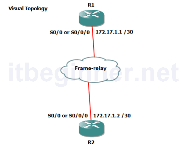
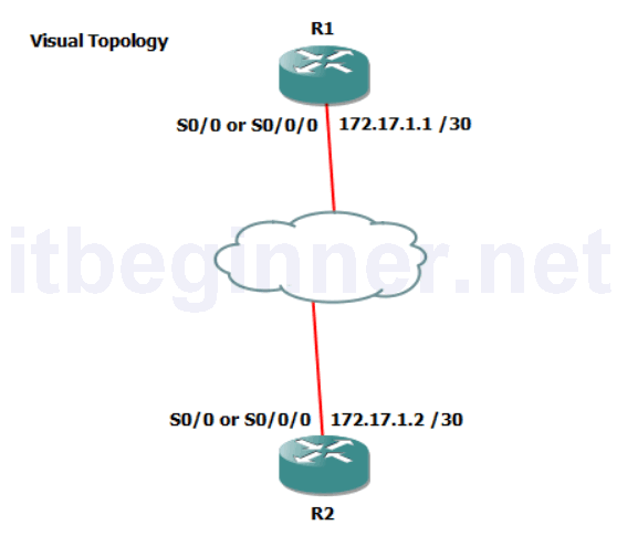
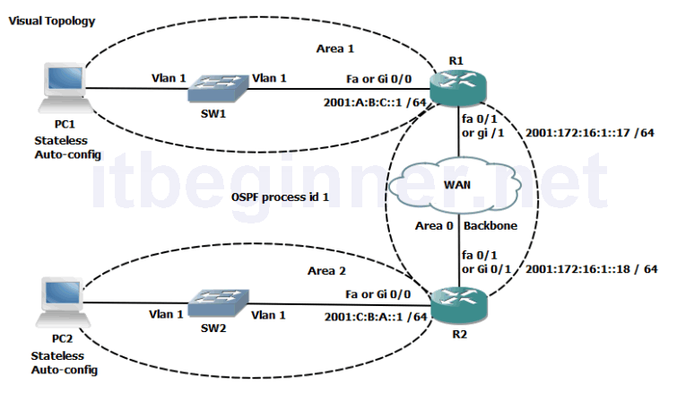
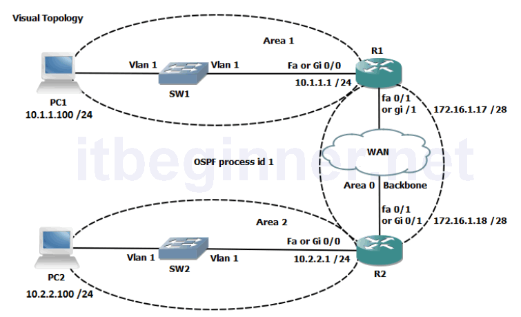
- Visual Topology
- Command List
- Task 1: Reload and check that the Switch is set to factory defaults.
- Task 2: Basic switch set-up.
- Task 3: Configure basic VLAN and Trunk connections.
- Task 4: Troubleshoot Trunk failure.
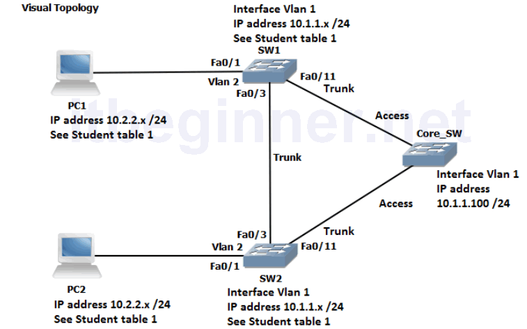
Visual Topology
Command List
| Command | Description |
|---|---|
| Configure Terminal | Enters global configuration mode |
| Copy run start | Saves your dynamic running config to NVRAM |
| Delete flash:vlan.dat | Deletes a file |
| Do command | Allows for the execution of commands located in a different mode |
| Enable | Enters privileged EXEC mode from user EXEC mode |
| End | Terminates configuration mode |
| Erase startup-config | Erases the startup-configuration from NVRAM |
| Exit | Exits current configuration mode |
| Hostname name | Sets a system name and is displayed within the system prompt |
| Interface type/slot/id | Enters the interface configuration mode |
| Interface Vlan 1 | Enters the interface configuration (SVI) for Vlan 1 and allows you to set the management IP address for the switch |
| IP address address & mask | Set an IP address and also the network/subnet mask |
| Line console 0 | Enters line console configuration mode |
| Logging synchronous | Prevents unsolicited messages from interfering when typing in your commands |
| Name vlan name | Used in vlan configuration mode to assign a descriptive name |
| Reload | Restarts the device |
| Show flash: | Displays the contents of the flash memory |
| Show startup-config | Displays the startup-config saved in NVRam |
| Show version | Displays hardware and software information |
| [no] Shutdown | Disables or enables an interface |
| Switchport access vlan id | Assigns a switchport to a data vlan |
| Switchport mode access | Puts the switchport into access mode |
| Switchport mode trunk | Puts the switchport into trunk mode |
| [no] Vlan id | Deletes or creates a vlan and enters vlan configuration mode |
* The instructor will assign you with a student ID (student 1 to 16).*
Please note that for this exercise students are expected to work in pairs.
Refer to the Student Table 1 when allocating IP addresses and VLANs, failure to do so will result in IP address conflict messages and inconsistent lab results.
Student Table 1.
| Student ID | PC IP address & mask | Switch SVI (VLAN 1) IP address | VLAN assignments | |
|---|---|---|---|---|
| Pair 1 | Student 1 | 10.2.2.101 /24 | 10.1.1.1 /24 | 2 & 3 |
| Pair 1 | Student 2 | 10.2.2.102 /24 | 10.1.1.2 /24 | 2 & 3 |
| Pair 2 | Student 3 | 10.2.2.103 /24 | 10.1.1.3 /24 | 2, 4 & 5 |
| Pair 2 | Student 4 | 10.2.2.104 /24 | 10.1.1.4 /24 | 2, 4 & 5 |
| Pair 3 | Student 5 | 10.2.2.105 /24 | 10.1.1.5 /24 | 2, 6 & 7 |
| Pair 3 | Student 6 | 10.2.2.106 /24 | 10.1.1.6 /24 | 2, 6 & 7 |
| Pair 4 | Student 7 | 10.2.2.107 /24 | 10.1.1.7 /24 | 2, 8 & 9 |
| Pair 4 | Student 8 | 10.2.2.108 /24 | 10.1.1.8 /24 | 2, 8 & 9 |
| Pair 5 | Student 9 | 10.2.2.109 /24 | 10.1.1.9 /24 | 2, 10 & 11 |
| Pair 5 | Student 10 | 10.2.2.110 /24 | 10.1.1.10 /24 | 2, 10 & 11 |
| Pair 6 | Student 11 | 10.2.2.111 /24 | 10.1.1.11 /24 | 2, 12 & 13 |
| Pair 6 | Student 12 | 10.2.2.112 /24 | 10.1.1.12 /24 | 2, 12 & 13 |
| Pair 7 | Student 13 | 10.2.2.113 /24 | 10.1.1.13 /24 | 2, 14 & 15 |
| Pair 7 | Student 14 | 10.2.2.114 /24 | 10.1.1.14 /24 | 2, 14 & 15 |
| Pair 8 | Student 15 | 10.2.2.115 /24 | 10.1.1.15 /24 | 2, 16 & 17 |
| Pair 8 | Student 16 | 10.2.2.116 /24 | 10.1.1.16 /24 | 2, 16 & 17 |
Task 1: Reload and check that the Switch is set to factory defaults.
Step 1: Assign an IP address to your PC using the details listed in Student Table 1. The PC should be fitted with two network adapters check with the instructor if you are unsure which network adapter should be configured.
Step 2: Access the Switch Console port using the method and information provided by the instructor.
Enter into privilege mode and use the erase startup-config command to remove any previous saved configuration.
(If you see any other prompt or are asked for a password contact the instructor).
Step 3: Switches hold information about logical VLANs in a database stored in their flash memory and it is necessary to delete this database to reset the Switch back to factory defaults. PLEASE BE VERY CAREFUL WHEN USING THE DELETE COMMAND.
From privilege mode type in the following command and follow the system messages (if you are unsure what to do, contact the instructor before answering any of the system messages).
Switch#Delete flash:vlan.dat
confirm the deletion
Step 4: Reload the Switch.
confirm the reload
Please note the Switch may take a few minutes to reload.
NB. ASK THE INSTRUCTOR TO RESET THE CORE_SW BACK TO FACTORY DEFAULTS!
Task 2: Basic switch set-up
Step 1: Change the hostname of the Switch to either SW1 or SW2
Step 2: Assign your Switch a management IP address using the values identified in the table below.
| Device | IP Address | Mask | SVI (logical interface) |
|---|---|---|---|
| SW1 | See Student Table 1 | 255.255.255.0 | vlan 1 |
| SW2 | See Student Table 1 | 255.255.255.0 | vlan 1 |
Remember to enable the SVI so the IP address is active.
Task 3: Configure basic VLAN and Trunk connections.
Step 1: Create the VLANs listed in Student Table 1 and label Vlan2 with your pair name.
Example, student 7 needs to create VLANs 2, 8 and 9 and name Vlan 2, Pair4. Use the default names for the other Vlans created.
Step 2: Disable interface fa0/1 and put it into an access state
Hint….switchport mode ?
Step 3: Re-assign interface fa0/1 and place it into Vlan 2
Step 4: enable interface fa0/1
Step 5: Disable all other interfaces except fa0/1 and Vlan 1
Step 6: Configure interface fa0/3 and interface fa0/11 to support trunking without using a dynamic protocol trunking protocol.
Hint…..switchport mode ?
In the table below indicate which modes generate DTP messages.
| Switchport mode access | |
| Switchport mode trunk | |
| Switchport mode dynamic auto | |
| Switchport mode dynamic desirable |
What is the command for disabling DTP?
Step 7: Enable interfaces fa0/3 and fa0/11 and disable DTP on all active interfaces.
Task 4: Troubleshooting Trunk failures
Step 1: Confirm with the instructor that the Core switch has been reset back to factory defaults?
Step 2: Ask the instructor to configure all of the ports on the Core switch as ACCESS ports.
When a switch has been reset to factory defaults and the ports have been set to access mode, what is the default allocated VLAN for the port?
Step 3: From privilege mode execute the following commands.
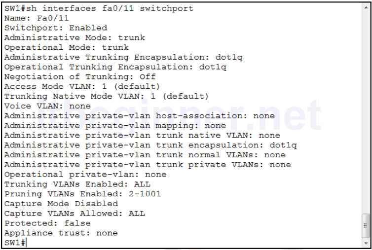
show interface fa0/3 switchport
show interface fa0/11 switchport
show interface fa0/1 switchport
Below are examples of output generated on SW1 but results should be similar on SW2 also.
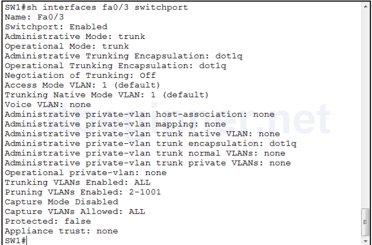
Observe the Switchport status, Administrative mode, Operational mode.
What do you think the Negotiation of Trunking: Off line indicates?
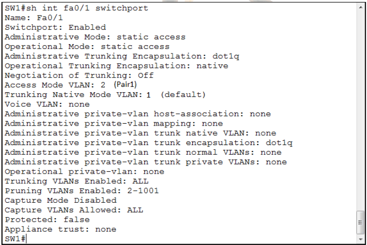
Interface Fa0/1 is attached to your PC.
Note that the Operational Mode is set to Static Access and the Access Mode VLAN is assigned to VLAN 2 with a name Pair1 (name will differ dependant on your pairings)
Step 4: ASK the Instructor to configure and enable the SVI (VLAN1) interface on the Core switch with an IP address of 10.1.1.100 /24.
Step 5: Ping 10.1.1.100 from you Switch
Explain, why the PING worked? Remembering that you have configured the switchport which connects you to the Core Switch as a Trunk link, however the Core Switch is configured in Static Access mode.
Step 6: From your PC ping 10.1.1.100.
Why does it fail?
Step 7: Save your running-config
Lab Answer Keys:
[sociallocker id=”4139″]Task 1: Reload and check that the Switch is set to factory defaults.
Step 1: Assign an IP address to your PC using the details listed in the visual topology diagram. The PC should be fitted with two network adapters, check with the instructor if you are unsure which network adapter should be configured.
Step 2: Access the Switch Console port using the method and information provided by the instructor.
Enter into privilege mode and use the erase startup-config command to remove any previous saved configuration.
Switch>enable
Switch#erase-config
Confirm action and do not save if prompted.
Step 3: Deleting the vlan database
Switch#Delete flash:vlan.dat
confirm the deletion
Step 4: Reload the Switch.
Switch#reload
confirm the reload
Task 2: Basic switch set-up
Step 1: Change the hostname of the Switch to either SW1 or SW2
Switch(config)#hostname SW1
or
Switch(config)#hostname SW2
Step 2: Assign your Switch a management IP address using the values identified in the table below.
| Device | IP Address | Mask | SVI (logical interface) |
|---|---|---|---|
| SW1 | See Student Table 1 | 255.255.255.0 | vlan 1 |
| SW2 | See Student Table 1 | 255.255.255.0 | vlan 1 |
Remember to enable the SVI so the IP address is active.
SW1(config)#interface vlan 1
SW1(config-if)#ip address 10.1.1.x 255.255.255.0
SW1(config-if)#no shut
or
SW2(config)#interface vlan 1
SW2(config-if)#ip address 10.1.1.x 255.255.255.0
SW2(config-if)#no shut
Task 3: Configure basic VLAN and Trunk connections.
Step 1: Create Vlan 2 and label it with a name of PAIRx
SW(config)#vlan 2
SW(config-vlan)#name PAIRx
Step 2: Disable interface fa0/1 and put it into an access state
SW(config)#int fa0/1
SW(config-if)#shut
SW(config-if)#switchport mode access
Step 3: Re-assign interface fa0/1 and place it into Vlan 2
SW(config-if)#switchport access vlan 2
Step 4: enable interface fa0/1
SW(config-if)#no shut
Step 5: Disable all other interfaces except fa0/1 and Vlan 1
SW(config)#int range fa0/2 - 24
SW(config-if-range)#shut
Step 6: Configure interface fa0/3 and interface fa0/11 to support trunking without using a dynamic protocol trunking protocol.
SW(config)#int fa0/3
SW(config-if)#switchport mode trunk
In the table below indicate which modes generate DTP messages.
Active will send DTP messages, Passive will only receive.
| Switchport mode access | Active operational state access only |
| Switchport mode trunk | Active operational state trunk only |
| Switchport mode dynamic auto | Passive operational state either trunk or access |
| Switchport mode dynamic desirable | Active operational state either trunk or access |
What is the command for disabling DTP?
SW(config-if)#switchport nonegotiate
Step 7: Enable interfaces fa0/3 and fa0/11 and disable DTP on all active interfaces.
SW(config)#int range fa0/1, fa0/3, fa0/11
SW(config-if-range)#switchport nonegotiate
SW(config-if-range)#no shut
Task 4: Troubleshooting Trunk failures
Step 2: Ask the instructor to configure all of the ports on the Core switch as ACCESS ports.
When a switch has been reset to factory defaults and the ports have been set to access mode, what is the default allocated VLAN for the port?
VLAN 1
Step 3: From privilege mode execute the following commands.
show interface fa0/3 switchport
show interface fa0/11 switchport
show interface fa0/1 switchport
Below are examples of output generated on SW1 but results should be similar on SW2 also.
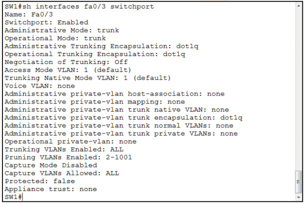
Observe the Switchport status, Administrative mode, Operational mode.
What do you think the Negotiation of Trunking: Off line indicates?
DTP is turned off
Step 4: ASK the Instructor to configure and enable the SVI (VLAN1) interface on the Core switch with an IP address of 10.1.1.100 /24.
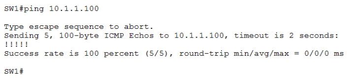
Step 5: Ping 10.1.1.100 from you Switch
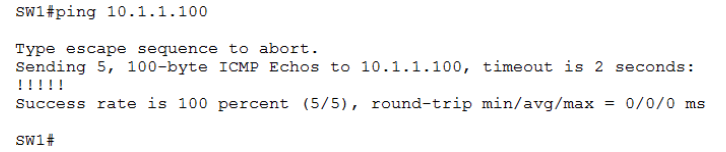
Explain, why the PING worked? Remembering that you have configured the switchport which connects you to the Core Switch as a Trunk link, however the Core Switch is configured in Static Access mode.
The switches will still communicate with each other if their operational states are different. Our configuration shows the Core Switch set to access mode vlan 1 and your switch set to Trunk with a native vlan of 1, and because the PING originates from vlan 1 your switch will send the PING frame down the trunk link untagged which will then be received at the core switch.
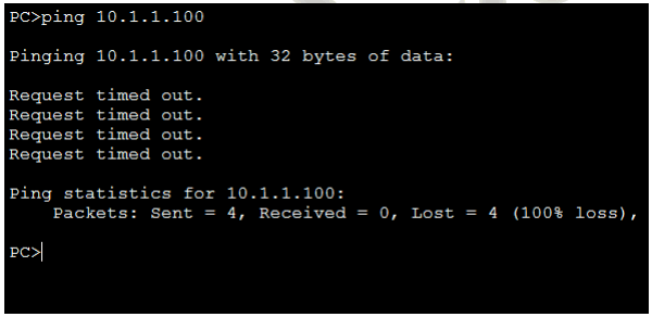
Step 6: From your PC ping 10.1.1.100.
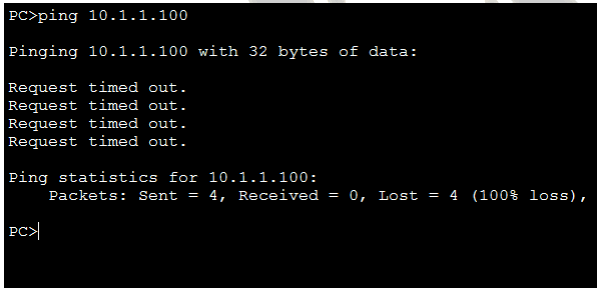
Why does it fail?
The PC is connected to switchport fa0/1 which was reassigned to vlan 2 earlier in the exercise, ports placed in vlan 2 can only communicate to other ports in vlan 2 unless layer 3 routing has been configured.
Step 7: Save your running-config
SW#copy run start[/sociallocker]