Lab 4-1: Implementing OSPF in a Multi-area Environment
Physical Topology Diagram
- Visual Topology
- Command Line
- Task 1: Configuring a multi-area OSPF network.
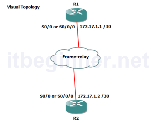
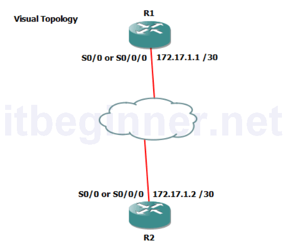
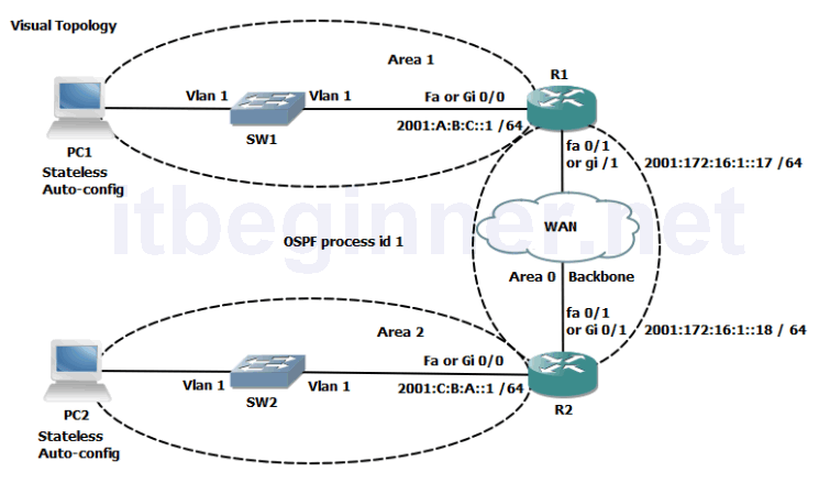
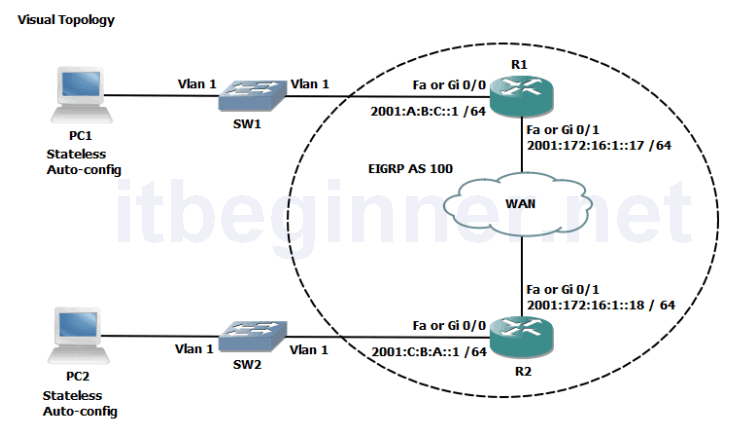
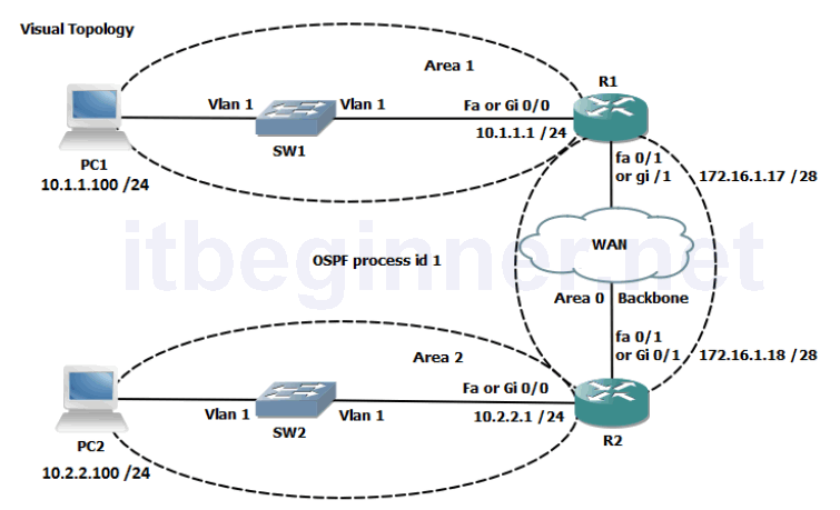
Visual Topology
Command List
| Command | Description |
|---|---|
| network address wildcard mask area id | Specifies which interfaces are OSPF capable and links them to an OSPF area |
| router ospf process id | Enters the OSPF router configuration mode |
| show ip ospf interfaces brief | Displays OSPF interface information |
| show ip ospf neighbor | Displays the contents of the adjacency table |
| show ip protocols | Display information about active running protocols. |
| show ip route | Displays the contents of the IPv4 routing table. (best paths) |
| show ip route ospf | Filters the output display to only show OSPF entries in the routing table. |
Task 1: Configuring a Multi-area OSPF Network
Step 1: Access the CLI on your router
Step 2: Check that your IPv4 addresses are still in place and create interface loopback0 and assign the IP address from the table below.
R#sh ip int brief
C:\>ipconfig
Rectify any IPv4 address problems
| Router | Interface | IPv4 address | Mask |
|---|---|---|---|
| R1 | fa0/0 or gi0/0 | 10.1.1.1 | 255.255.255.0 |
| R1 | fa0/1 or gi 0/1 | 172.16.1.17 | 255.255.255.240 |
| R1 | loopback 0 | 1.1.1.1 | 255.255.255.255 |
| R2 | fa0/0 or gi0/0 | 10.2.2.1 | 255.255.255.0 |
| R2 | fa0/1 or gi0/1 | 172.16.1.18 | 255.255.255.240 |
| R2 | loopback 0 | 2.2.2.2 | 255.255.255.255 |
Step 3: Enter the OSPF router configuration mode and assign a process id of 1
Do process IDs need to match for routers to form an adjacency?
Step 4: Use the Network command with an explicit wildcard mask to enable the ethernet and the loopback interfaces. Use the table below for their area assignment
| Router | Interface | Area |
|---|---|---|
| R1 | fa0/0 or gi0/0 | 1 |
| R1 | fa0/1 or gi0/1 | 0 |
| R1 | loopback 0 | 0 |
| R2 | fa0/0 or gi0/0 | 2 |
| R2 | fa0/1 or gi0/1 | 0 |
| R2 | loopback 0 | 0 |
Step 5: Enter the sh ip protocol command and write down the router ID
Why did the router select this value.
Is there another way of controlling the router ID and if so, how?
Step 6: Run the sh ip ospf nei command (these are example outputs)
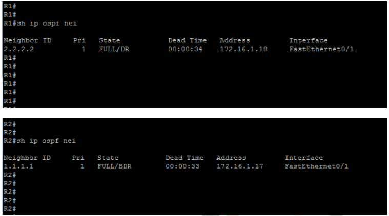
Note that both the router ID and the actual IP address of the neighbours interface are displayed using this command. The top picture displays a neighbour with a router ID of 2.2.2.2 and a connecting interface of 172.16.1.18.
Why do we see a DR and BDR in the pictures above but below we see a DR and DRother?
Using the sh ip protcol command we can find out information about the OSPF configuration.
Run this command on your router and analyze the result.
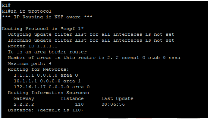
This display clearly identifies the Router ID, which networks (interfaces) are allocated to which areas, and a maximum equal cost load balancing of up to 4 paths.
Why is it an Area Border Router (ABR) ?
Step 7: View the contents of the IPv4 routing table and would you expect to see any OSPF entries?
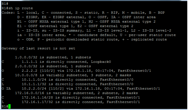
You should observe OSPF generated O and O IA entries in your routing table.
Explain the difference between the two?
Step 7: Save your running-config.
Lab Answer Keys:
[sociallocker id=”4139″]Task 1: Configuring a Multi-area OSPF Network
Step 2: Check that your IPv4 addresses are still in place and create interface loopback0 and assign the IP address from the table below.
R#sh ip int brief
R(config)#int loopback 0
R1 only....
R1(config-if)#ip address 1.1.1.1 255.255.255.255
R2 only....
R2(config-if)#ip address 2.2.2.2 255.255.255.255

C:\>ipconfig
Rectify any IPv4 address problems
| Router | Interface | IPv4 address | Mask |
|---|---|---|---|
| R1 | fa0/0 or gi0/0 | 10.1.1.1 | 255.255.255.0 |
| R1 | fa0/1 or gi 0/1 | 172.16.1.17 | 255.255.255.240 |
| R1 | loopback 0 | 1.1.1.1 | 255.255.255.255 |
| R2 | fa0/0 or gi0/0 | 10.2.2.1 | 255.255.255.0 |
| R2 | fa0/1 or gi0/1 | 172.16.1.18 | 255.255.255.240 |
| R2 | loopback 0 | 2.2.2.2 | 255.255.255.255 |
Step 3: Enter the OSPF router configuration mode and assign a process id of 1
R(config)#router ospf 1
R(config-router)#
Do process IDs need to match for routers to form an adjacency?
NO, the process ID is locally significant.
Step 4: Use the Network command with an explicit wildcard mask to enable the ethernet and the loopback interfaces. Use the table below for their area assignment.
| Router | Interface | Area |
|---|---|---|
| R1 | fa0/0 or gi0/0 | 1 |
| R1 | fa0/1 or gi0/1 | 0 |
| R1 | loopback 0 | 0 |
| R2 | fa0/0 or gi0/0 | 2 |
| R2 | fa0/1 or gi0/1 | 0 |
| R2 | loopback 0 | 0 |
R1 only....
R1(config-router)#network 10.1.1.1 0.0.0.0 area 1
R1(config-router)#network 172.16.1.17 0.0.0.0 area 0
R2 only....
R2(config-router)#network 10.2.2.1 0.0.0.0 area 2
R2(config-router)#network 172.16.1.18 0.0.0.0 area 0
Step 5: Enter the sh ip protocol command and write down the router ID
Why did the router select this value.
Used the ip address of the loopback address.
Is there another way of controlling the router ID and if so, how?
Router-ID command in the router configuration mode
Step 6: Run the sh ip ospf nei command (these are example outputs)
Note that both the router ID and the actual IP address of the neighbours interface are displayed using this command. The top picture displays a neighbour with a router ID of 2.2.2.2 and a connecting interface of 172.16.1.18.
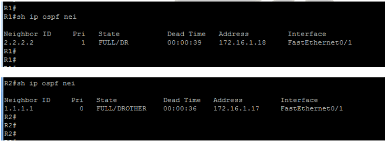
Why do we see a DR and BDR in the pictures above but below we see a DR and DRother?
The router detects from the interface type that an election for a DR, BDR and DRother needs to take place.
In the first set of output displays both routers are using the default ip ospf priority of 1 and out of the two routers one will demote itself to a BDR.
The second set of output displays one router with an ip ospf priority of 0, which means it will not participate in the election process and take on the role of DRother.
Using the sh ip protcol command we can find out information about the OSPF configuration.
Run this command on your router and analyze the result.
This display clearly identifies the Router ID, which networks (interfaces) are allocated to which areas, and a maximum equal cost load balancing of up to 4 paths.
Why is it an Area Border Router (ABR) ?
OSPF interfaces are placed in different area’s
Step 7: View the contents of the IPv4 routing table and would you expect to see any OSPF entries?
Yes, advertised from the other router
You should observe OSPF generated O and O IA entries in your routing table.
Explain the difference between the two?
O entries represent intra-area routes, routes which originate inside your area
O IA entries represent inter-area routes, routes which originate within OSPF but from a different area
Step 7: Save your running-config.
R#copy run start[/sociallocker]