Lab 4-3: Implementing OSPF
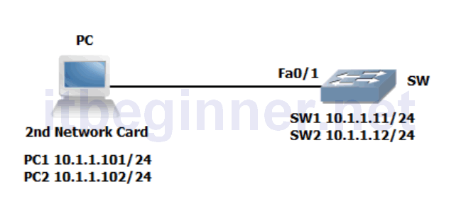
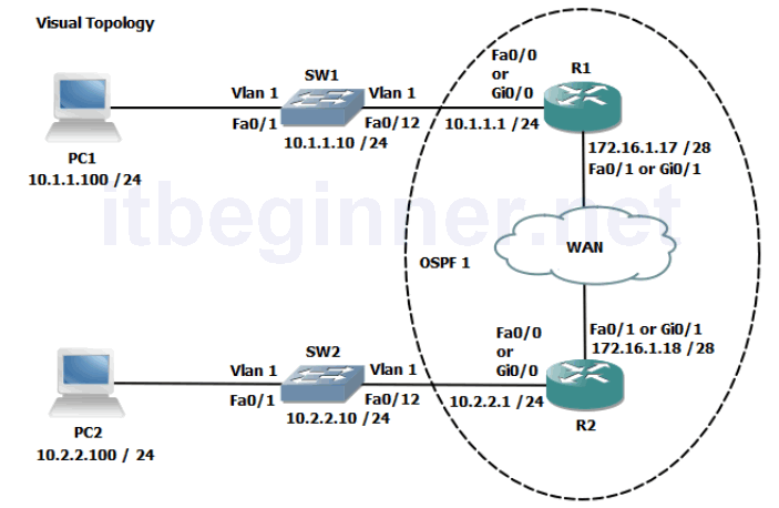
Visual Topology
Command Line
| Command | Description |
|---|---|
| Erase startup-config or Write erase | Removes the startup-configuration from NVram |
| Hostname | Defines a system device name shown in the prompt |
| interface name | Enters interface configuration mode |
| ip address ip address mask | Assigns an IP address to an interface |
| Network {address [wildcard mask]} area id | Defines which interfaces are part of the OSPF routing process |
| router ospf process id | Enters the OSPF configuration mode and defines the locally significant process id |
| show ip ospf interface | Displays interface information related to OSPF |
| show ip ospf neighbor | Shows the output of the OSPF adjacency table |
| show ip route | Shows the contents of the IPv4 routing table |
| [no] shutdown | Disables or enables an interface |
This lab exercise requires two students to work together to complete the tasks. Use the
visual topology diagram to ascertain the correct IP addressing plan for your PC, Router and
Switch.
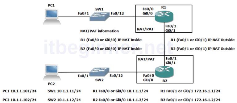
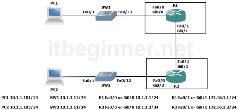
Physical Topology Diagram
- Task 1: Setting-up a Routed WAN connection.
- Task 2: Configuring OSPF.
Lab 4-3: Implementing OSPF
Task 1: Setting-up a Routed WAN connection.
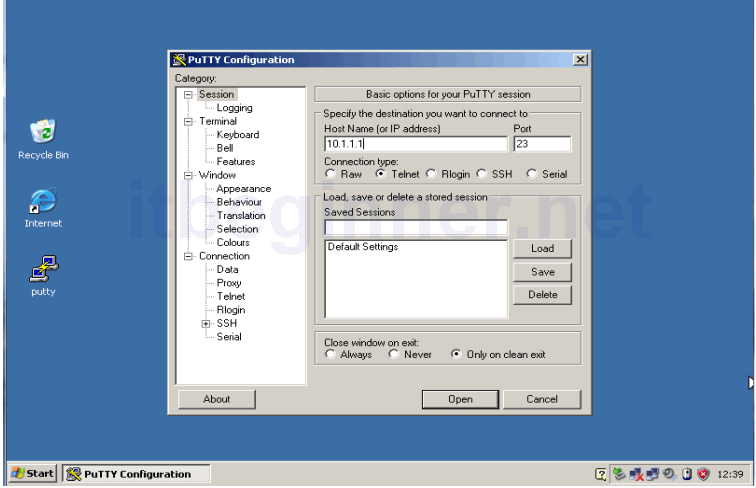
Step 1: Access the CLI on both your switch and router.
Step 2: Clear down their current configuration and reload the devices using the erase startup-config and reload commands. Make sure you do this on both the router and the switch.
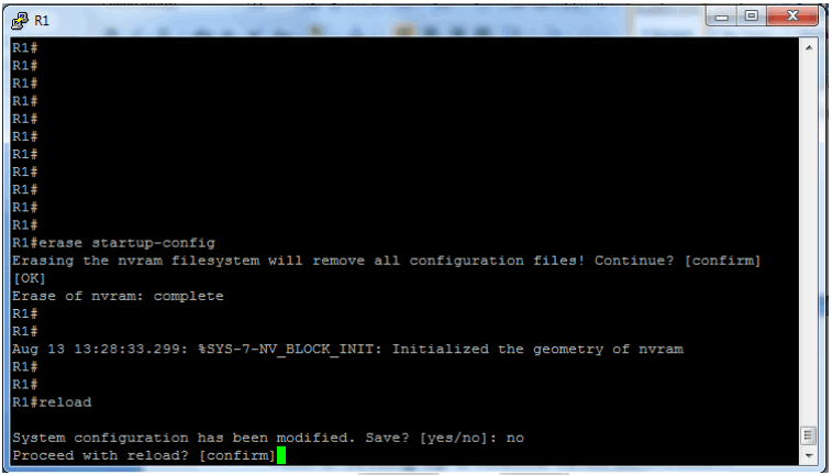
If the system indicates that the system configuration has been modified and do you want to save ? Answer no
Confirm the reload.
Step 3: The devices have been set back to factory defaults (well almost) ignore and abort the setup dialogue options.
Using the information in the visual topology diagram, setup the correct IP addresses and hostnames on all 3 devices.
Hint....
Switch#conf t
Switch(config)#hostname SW1
SW1(config)#interface vlan 1
SW1(config-if)#ip address 10.1.1.10 255.255.255.0
SW1(config-if)#no shut
Router#conf t
Router(config)#hostname R1
R1(config)#interface fa0/0
R1(config-if)#ip address 10.1.1.1 255.255.255.0
R1(config-if)#no shut
R1(config-if)#interface fa0/1
R1(config-if)#ip address 172.16.1.17 255.255.255.240
R1(config-if)#no shut
Check that the interfaces are up/up, troubleshoot any discrepancies.
Remember to set a static IP address on the PC interface and check connectivity between the PC and its default router.
Task 2: Configuring OSPF.
By default routers do not run any dynamic routing protocols, however routing between IPv4 locally connected interfaces is enabled by default.
Step 1: Execute the relevant show command to display the contents of the routing table.
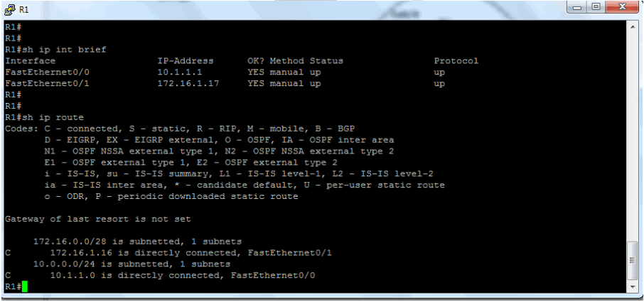
The table displays only two connected subnets and therefore this router only has paths for subnets 10.1.1.0 and 172.16.1.16.
Step 2: Enter OSPF configuration mode and use a process id of 1.
Rx(config)#Router ospf 1
Step 3: Enable both interfaces for ospf and place them in the backbone area 0
R1 only.....
R1(config-router)#network 10.1.1.1 0.0.0.0 area 0
R1(config-router)#network 172.16.1.17 0.0.0.0 area 0
R2 only.....
R2(config-router)#network 10.2.2.1 0.0.0.0 area 0
R2(config-router)#network 172.16.1.18 0.0.0.0 area 0
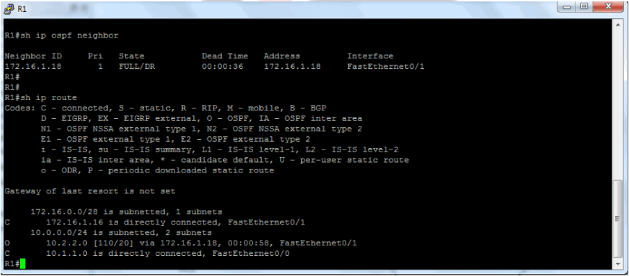
Step 4: Check the contents of the routing table. Do you see any additional entries?
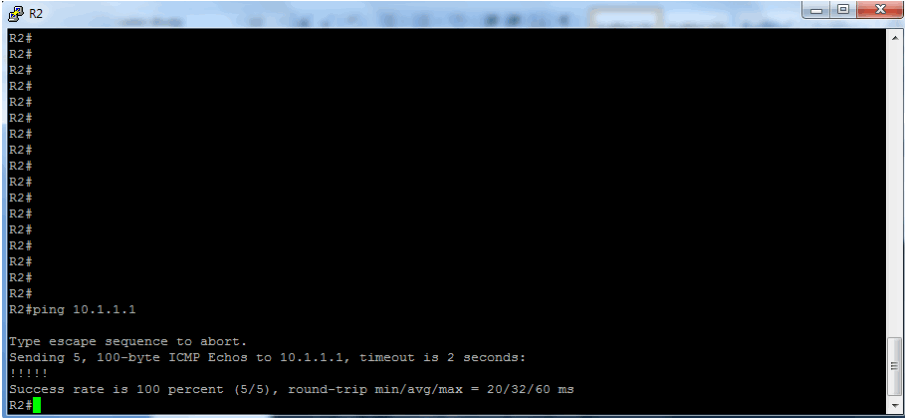
Step 5: Check connectivity by pinging the IP address of the other router’s fa0/0 interface.
Step 6: Save the configuration on both the switch and router.
Lab Answer Keys:
[sociallocker id=”4139″]
This lab exercise requires two students to work together to complete the tasks. Use the visual topology diagram to ascertain the correct IP addressing plan for your PC, Router and Switch.
Task 1: Setting-up a Routed WAN connection.
Step 1: Access the CLI on both your switch and router.
Step 2: Clear down their current configuration and reload the devices using the erase startup-config and reload commands. Make sure you do this on both the router and the switch.
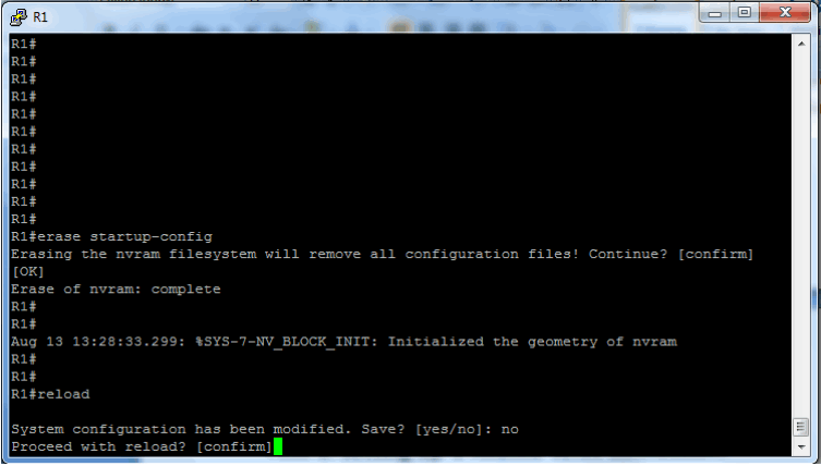
If the system indicates that the system configuration has been modified and do you want to save ? Answer no
Confirm the reload.
Step 3: The devices have been set back to factory defaults (well almost) ignore and abort the setup dialogue options.
Using the information in the visual topology diagram, setup the correct IP addresses and hostnames on all 3 devices.
Hint....
Switch>en
Switch#conf t
Switch(config)#hostname SW1
SW1(config)#interface vlan 1
SW1(config-if)#ip address 10.1.1.10 255.255.255.0
SW1(config-if)#no shut
Router>en
Router#conf t
Router(config)#hostname R1
R1(config)#interface fa0/0
R1(config-if)#ip address 10.1.1.1 255.255.255.0
R1(config-if)#no shut
R1(config-if)#interface fa0/1
R1(config-if)#ip address 172.16.1.17 255.255.255.240
R1(config-if)#no shut
Check that the interfaces are up/up, troubleshoot any discrepancies.
Remember to set a static IP address on the PC interface and check connectivity between the PC and its default router.
Task 2: Configuring OSPF.
By default routers do not run any dynamic routing protocols, however routing between IPv4 locally connected interfaces is enabled by default.
Step 1: Execute the relevant show command to display the contents of the routing table.
R#sh ip route
The table displays only two connected subnets and therefore this router only has paths for subnets 10.1.1.0 and 172.16.1.16.
Step 2: Enter OSPF configuration mode and use a process id of 1.
R(config)#Router ospf 1
Step 3: Enable both interfaces for ospf and place them in the backbone area 0
R1 only.....
R1(config-router)#network 10.1.1.1 0.0.0.0 area 0
R1(config-router)#network 172.16.1.17 0.0.0.0 area 0
R2 only.....
R2(config-router)#network 10.2.2.1 0.0.0.0 area 0
R2(config-router)#network 172.16.1.18 0.0.0.0 area 0
Step 4: Check the contents of the routing table. Do you see any additional entries?
Yes you now see an OSPF advertised route from the neighbouring router
Step 6: Save the configuration on both the switch and router.
R#copy run start
[/sociallocker]