Introduction to Networks Instructor Materials – Chapter 4: Network Access
4.0 Network Access
4.0.1 Introduction
4.0.1.1 Introduction
To support our communication, the OSI model divides the functions of a data network into layers. Each layer works with the layers above and below in order to transmit data. Two layers within the OSI model are so closely tied, that according to the TCP/IP model, they are in essence one layer. Those two layers are the data link layer and the physical layer.
On the sending device, it is the role of the data link layer to prepare data for transmission and control how that data accesses the physical media. However, the physical layer controls how the data is transmitted onto the physical media by encoding the binary digits that represent data into signals.
On the receiving end, the physical layer receives signals across the connecting media. After decoding the signal back into data, the physical layer passes the data to the data link layer for acceptance and processing.
This chapter begins with the general functions of the physical layer and the standards and protocols that manage the transmission of data across local media. It also introduces the functions of the data link layer and the protocols associated with it.
Upon completion of this chapter you will be able to:
- Identify device connectivity options.
- Describe the purpose and functions of the physical layer in the network.
- Describe basic principles of the physical layer standards.
- Identify the basic characteristics of copper cabling.
- Build a UTP cable used in Ethernet networks.
- Describe fiber-optic cabling and its main advantages over other media.
- Describe wireless media.
- Select the appropriate media for a given requirement and connect devices.
- Describe the purpose and function of the data link layer in preparing communication for transmission on specific media.
- Describe the Layer 2 frame structure and identify generic fields.
- Identify several sources for the protocols and standards used by the data link layer.
- Compare the functions of logical topologies and physical topologies.
- Describe the basic characteristics of media access control methods on WAN topologies.
- Describe the basic characteristics of media access control methods on LAN topologies.
- Describe the characteristics and functions of the data link frame.
4.0.1.2 Activity – Managing the Medium
You and your colleague are attending a networking conference. There are many lectures and presentations held during this event, and because they overlap, each of you can only choose a limited set of sessions to attend.
Therefore, you decide to split, each of you attending a separate set of presentations, and after the event ends, you share the slides and the knowledge each of you gained during the event.
Try to answer the following questions:
- How would you personally organize a conference where multiple sessions are held at the same time? Would you put all of them into a single conference room or would you use multiple rooms? What would be the reason?
- Assume that the conference room is properly fitted with audiovisual equipment to display large-size video and amplify voice. If a person wanted to attend a specific session, does the seating arrangement make a difference, or is it sufficient to visit the proper conference room?
- Would it be considered positive or harmful if the speech from one conference room somehow leaked into another?
- If questions or inquiries arise during a presentation, should attendees simply shout out their question, or should there be some form of process for handling questions, such as documenting them and handing them over to a facilitator? What would happen without this process?
- If an interesting topic elicits a larger discussion where many attendees have questions or comments, can this result in the session running out of its time without going through the entire intended content? Why is that so?
- Imagine that the session is a panel, i.e. a more free discussion of attendees with panelists and optionally with themselves. If a person wants to address another person within the same room, can he/she do it directly? What would be necessary to do if a panelist wanted to invite another person to join who is not presently in the room?
- What was accomplished by the isolation of multiple sessions into separate conference rooms if, after the event, people can meet and share the information?
Class Activity – Let Me Tell You What I Heard at a Conference Instructions ./.
4.1 Physical Layer Protocols
4.1.1 Getting It Connected
4.1.1.1 Connecting to the Network
Whether connecting to a local printer in the home or to a web site in another country, before any network communications can occur, a physical connection to a local network must be established first. A physical connection can be a wired connection using a cable or a wireless connection using radio waves.
The type of physical connection used is totally dependent upon the setup of the network. For example, in many corporate offices, employees have desktop or laptop computers that are physically connected, via cable, to a shared switch. This type of setup is a wired network, in which data is transmitted across a physical cable.
In addition to wired connections, some businesses may also offer wireless connections for laptops, tablets, and smartphones. With wireless devices, data is transmitted using radio waves. The use of wireless connectivity is becoming more common as individuals, and businesses alike, discover the advantages of offering wireless services. In order to offer wireless capability, a network must incorporate a wireless access point (WAP) for devices to connect to.
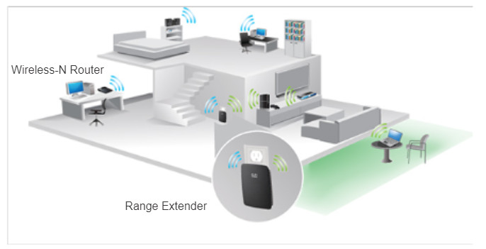
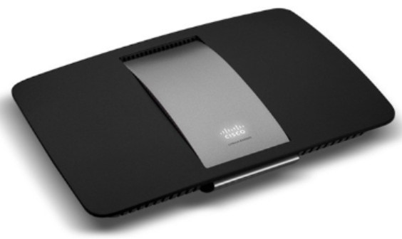
Switch devices and wireless access points are often two separate dedicated devices within a network implementation. However, there are also devices that offer both wired and wireless connectivity. In many homes, for example, individuals are implementing home integrated service routers (ISRs), as shown in Figure 1. ISRs offer a switching component with multiple ports, allowing multiple devices to be connected to the local area network (LAN) using cables, as shown in Figure 2. Additionally, many ISRs also include a WAP, which allows wireless devices to connect as well.
[tabs type=”horizontal”]
[tabs_head]
[tab_title]Home Router[/tab_title]
[tab_title]Connecting to the Wired LAN[/tab_title]
[/tabs_head]
[tab]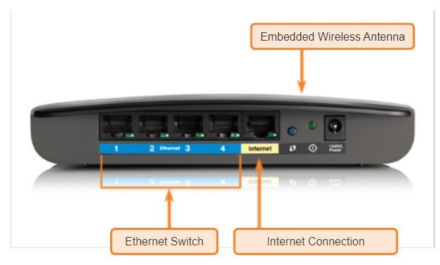 [/tab]
[tab]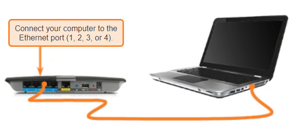 [/tab]
[/tabs]
4.1.1.2 Network Interface Cards
Network Interface Cards (NICs) connect a device to the network. Ethernet NICs are used for a wired connection whereas WLAN (Wireless Local Area Network) NICs are used for wireless. An end-user device may include one or both types of NICs. A network printer, for example, may only have an Ethernet NIC, and therefore, must connect to the network using an Ethernet cable. Other devices, such as tablets and smartphones, might only contain a WLAN NIC and must use a wireless connection.
Not all physical connections are equal, in terms of the performance level, when connecting to a network.
For example, a wireless device will experience degradation in performance based on its distance to a wireless access point. The further the device is from the access point the weaker the wireless signal it receives. This can mean less bandwidth or no wireless connection at all. The figure shows that a wireless range extender can be used to regenerate the wireless signal to other parts of the house that are too far from the wireless access point. Alternatively, a wired connection will not degrade in performance, however, is extremely limited in movement and generally requires static positioning.
All wireless devices must share access to the airwaves connecting to the wireless access point. This means slower network performance may occur as more wireless devices access the network simultaneously. A wired device does not need to share its access to the network with other devices. Each wired device has a separate communications channel over its own Ethernet cable. This is important when considering some applications, like online gaming, streaming video, and video conferencing, which require more dedicated bandwidth than other applications.
Over the next couple of topics you will learn more about the physical layer connections that occur and how those connections affect the transportation of data.
4.1.2 Purpose of the Physical Layer
4.1.2.1 The Physical Layer
The OSI physical layer provides the means to transport the bits that make up a data link layer frame across the network media. This layer accepts a complete frame from the data link layer and encodes it as a series of signals that are transmitted onto the local media. The encoded bits that comprise a frame are received by either an end device or an intermediate device.
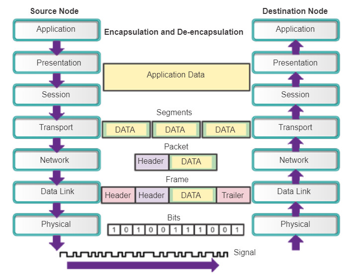
The process that data undergoes from a source node to a destination node is:
- The user data is segmented by the transport layer, placed into packets by the network layer, and further encapsulated as frames by the data link layer.
- The physical layer encodes the frames and creates the electrical, optical, or radio wave signals that represent the bits in each frame.
- These signals are then sent on the media one at a time.
- The destination node physical layer retrieves these individual signals from the media, restores them to their bit representations, and passes the bits up to the data link layer as a complete frame.
4.1.2.2 Physical Layer Media
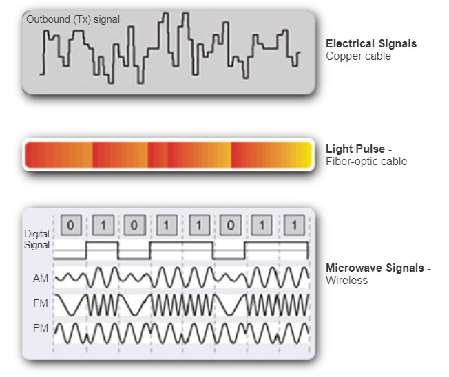
There are three basic forms of network media. The physical layer produces the representation and groupings of bits for each type of media as:
- Copper cable: The signals are patterns of electrical pulses.
- Fiber-optic cable: The signals are patterns of light.
- Wireless: The signals are patterns of microwave transmissions.
The figure displays signaling examples for copper, fiber-optic, and wireless.
To enable physical layer interoperability, all aspects of these functions are governed by standard organizations.
4.1.2.3 Physical Layer Standards
The protocols and operations of the upper OSI layers are performed in software designed by software engineers and computer scientists. For example, the services and protocols in the TCP/IP suite are defined by the Internet Engineering Task Force (IETF) in RFCs as shown in Figure 1.
The physical layer consists of electronic circuitry, media, and connectors developed by engineers. Therefore, it is appropriate that the standards governing this hardware are defined by the relevant electrical and communications engineering organizations.
There are many different international and national organizations, regulatory government organizations, and private companies involved in establishing and maintaining physical layer standards. For instance, the physical layer hardware, media, encoding, and signaling standards are defined and governed by the:
- International Organization for Standardization (ISO)
- Telecommunications Industry Association/Electronic Industries Association (TIA/EIA)
- International Telecommunication Union (ITU)
- American National Standards Institute (ANSI)
- Institute of Electrical and Electronics Engineers (IEEE)
- National telecommunications regulatory authorities including the Federal Communication Commission (FCC) in the USA and the European Telecommunications Standards Institute (ESTI)
In addition to these, there are often regional cabling standards groups such as CSA (Canadian Standards Association), CENELEC (European Committee for Electrotechnical Standardization), and JSA/JSI (Japanese Standards Association), developing local specifications.
Figure 2 lists the major contributors and some of their relevant physical layer standards.
[tabs type=”horizontal”]
[tabs_head]
[tab_title]Figure 1[/tab_title]
[tab_title]Figure 2[/tab_title]
[/tabs_head]
[tab]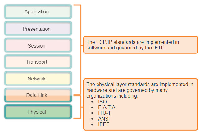 [/tab]
[tab]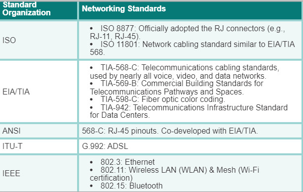 [/tab]
[/tabs]
4.1.2.4 Lab – Identifying Network Devices and Cabling
In this lab, you will complete the following objectives:
- Part 1: Identify Network Devices
- Part 2: Identify Network Media
Lab – Identifying Network Devices and Cabling ./.
4.1.3 Fundamental Principles of Layer 1
4.1.3.1 Physical Layer Fundamental Principles
The physical layer standards address three functional areas:
Physical Components
The physical components are the electronic hardware devices, media, and other connectors that transmit and carry the signals to represent the bits. Hardware components such as network adapters (NICs), interfaces and connectors, cable materials, and cable designs are all specified in standards associated with the physical layer. The various ports and interfaces on a Cisco 1941 router are also examples of physical components with specific connectors and pinouts resulting from standards.
Encoding
Encoding or line encoding is a method of converting a stream of data bits into a predefined “code”. Codes are groupings of bits used to provide a predictable pattern that can be recognized by both the sender and the received. In the case of networking, encoding is a pattern of voltage or current used to represent bits; the 0s and 1s.
In addition to creating codes for data, encoding methods at the physical layer may also provide codes for control purposes such as identifying the beginning and end of a frame.
Common network encoding methods include:
- Manchester encoding: A 0 is represented by a high to low voltage transition and a 1 is represented as a low to high voltage transition. This type of encoding is used in older versions of Ethernet, RFID and Near Field Communication.
- Non-Return to Zero (NRZ): This is a common means of encoding data that has two states termed “zero” and “one” and no neutral or rest position. A 0 may be represented by one voltage level on the media and a 1 might be represented by a different voltage on the media.
Note: Faster data rates require more complex encoding, such as 4B/5B, however, explanation of these methods is beyond the scope of this course.
Signaling
The physical layer must generate the electrical, optical, or wireless signals that represent the “1” and “0” on the media. The method of representing the bits is called the signaling method. The physical layer standards must define what type of signal represents a “1” and what type of signal represents a “0”. This can be as simple as a change in the level of an electrical signal or optical pulse. For example, a long pulse might represent a 1, whereas a short pulse represents a 0.
This is similar to how Morse code is used for communication. Morse code is another signaling method that uses a series of on-off tones, lights, or clicks to send text over telephone wires or between ships at sea.
Signals can be transmitted in one of two ways:
- Asynchronous: Data signals are transmitted without an associated clock signal. The time spacing between data characters or blocks may be of arbitrary duration, meaning the spacing is not standardized. Therefore, frames require start and stop indicator flags.
- Synchronous: Data signals are sent along with a clock signal which occurs at evenly spaced time durations referred to as the bit time.
There are many ways to transmit signals. A common method to send data is using modulation techniques. Modulation is the process by which the characteristic of one wave (the signal) modifies another wave (the carrier). The following modulation techniques have been widely used in transmitting data on a medium:
- Frequency modulation (FM): A method of transmission in which the carrier frequency varies in accordance with the signal.
- Amplitude modulation (AM): A transmission technique in which the amplitude of the carrier varies in accordance with the signal.
- Pulse-coded modulation (PCM): A technique in which an analog signal, such as a voice, is converted into a digital signal by sampling the signal’s amplitude and expressing the different amplitudes as a binary number. The sampling rate must be at least twice the highest frequency in the signal.
The nature of the actual signals representing the bits on the media will depend on the signaling method in use. Some methods may use one attribute of signal to represent a single 0 and use another attribute of signal to represent a single 1.
Figure 2 illustrates the how AM and FM techniques are used to send a signal.
[tabs type=”horizontal”]
[tabs_head]
[tab_title]Figure 1[/tab_title]
[tab_title]Figure 2[/tab_title]
[/tabs_head]
[tab]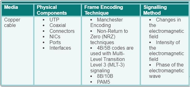 [/tab]
[tab]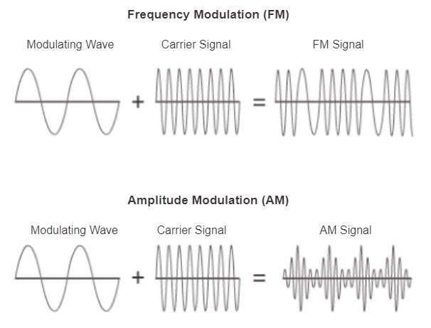 [/tab]
[/tabs]
4.1.3.2 Bandwidth
Different physical media support the transfer of bits at different speeds. Data transfer is usually discussed in terms of bandwidth and throughput.
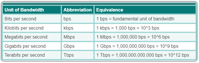
Bandwidth is the capacity of a medium to carry data. Digital bandwidth measures the amount of data that can flow from one place to another in a given amount of time. Bandwidth is typically measured in kilobits per second (kb/s) or megabits per second (Mb/s).
The practical bandwidth of a network is determined by a combination of factors:
- The properties of the physical media
- The technologies chosen for signaling and detecting network signals
Physical media properties, current technologies, and the laws of physics all play a role in determining available bandwidth.
The table shows the commonly used units of measure for bandwidth.
4.1.3.3 Throughput
Throughput is the measure of the transfer of bits across the media over a given period of time.
Due to a number of factors, throughput usually does not match the specified bandwidth in physical layer implementations. Many factors influence throughput including:
- The amount of traffic
- The type of traffic
- The latency created by the number of network devices encountered between source and destination
Latency refers to the amount of time, to include delays, for data to travel from one given point to another.
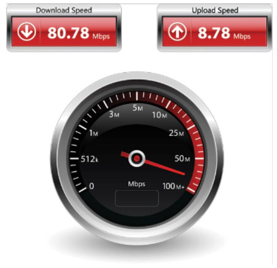
In an internetwork or network with multiple segments, throughput cannot be faster than the slowest link of the path from source to destination. Even if all or most of the segments have high bandwidth, it will only take one segment in the path with low throughput to create a bottleneck to the throughput of the entire network.
There are many online speed tests that can reveal the throughput of an Internet connection. The figure provides sample results from a speed test.
Note: There is a third measurement to measure the transfer of usable data that is known as goodput. Goodput is the measure of usable data transferred over a given period of time. Goodput is throughput minus traffic overhead for establishing sessions, acknowledgements, and encapsulation.
4.1.3.4 Types of Physical Media
The physical layer produces the representation and groupings of bits as voltages, radio frequencies, or light pulses. Various standards organizations have contributed to the definition of the physical, electrical, and mechanical properties of the media available for different data communications. These specifications guarantee that cables and connectors will function as anticipated with different data link layer implementations.
As an example, standards for copper media are defined for the:
- Type of copper cabling used
- Bandwidth of the communication
- Type of connectors used
- Pinout and color codes of connections to the media
- Maximum distance of the media
The figure shows different types of interfaces and ports available on a 1941 router.

4.1.3.5 Activity – Physical Layer Terminology
4.2 Network Media
4.2.1 Copper Cabling
4.2.1.1 Characteristics of Copper Media
Networks use copper media because it is inexpensive, easy to install, and has low resistance to electrical current. However, copper media is limited by distance and signal interference.
Data is transmitted on copper cables as electrical pulses. A detector in the network interface of a destination device must receive a signal that can be successfully decoded to match the signal sent. However, the longer the signal travels, the more it deteriorates in a phenomenon referred to as signal attenuation. For this reason, all copper media must follow strict distance limitations as specified by the guiding standards.
The timing and voltage values of the electrical pulses are also susceptible to interference from two sources:
- Electromagnetic interference (EMI) or radio frequency interference (RFI) – EMI and RFI signals can distort and corrupt the data signals being carried by copper media. Potential sources of EMI and RFI include radio waves and electromagnetic devices such as fluorescent lights or electric motors as shown in the figure.
- Crosstalk – Crosstalk is a disturbance caused by the electric or magnetic fields of a signal on one wire to the signal in an adjacent wire. In telephone circuits, crosstalk can result in hearing part of another voice conversation from an adjacent circuit. Specifically, when electrical current flows through a wire, it creates a small, circular magnetic field around the wire which can be picked up by an adjacent wire.
Play the animation in the figure to see how data transmission can be affected by interference.
To counter the negative effects of EMI and RFI, some types of copper cables are wrapped in metallic shielding and require proper grounding connections.
To counter the negative effects of crosstalk, some types of copper cables have opposing circuit wire pairs twisted together which effectively cancels the crosstalk.
The susceptibility of copper cables to electronic noise can also be limited by:
- Selecting the cable type or category most suited to a given networking environment.
- Designing a cable infrastructure to avoid known and potential sources of interference in the building structure.
- Using cabling techniques that include the proper handling and termination of the cables.

4.2.1.2 Copper Media
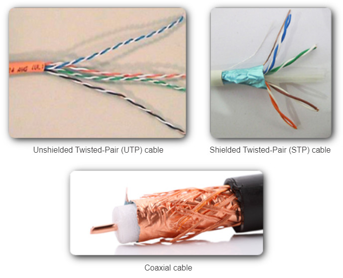
There are three main types of copper media used in networking:
- Unshielded Twisted-Pair (UTP)
- Shielded Twisted-Pair (STP)
- Coaxial
These cables are used to interconnect nodes on a LAN and infrastructure devices such as switches, routers, and wireless access points. Each type of connection and the accompanying devices have cabling requirements stipulated by physical layer standards.
Different physical layer standards specify the use of different connectors. These standards specify the mechanical dimensions of the connectors and the acceptable electrical properties of each type. Networking media use modular jacks and plugs to provide easy connection and disconnection. Also, a single type of physical connector may be used for multiple types of connections. For example, the RJ-45 connector is widely used in LANs with one type of media and in some WANs with another media type.
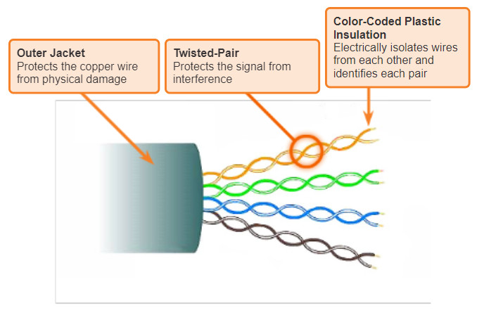
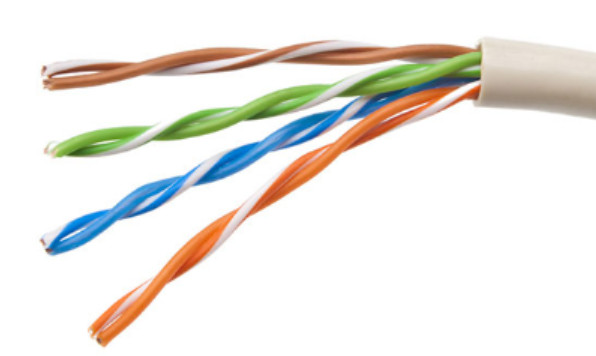
4.2.1.3 Unshielded Twisted-Pair Cable
Unshielded twisted-pair (UTP) cabling is the most common networking media. UTP cabling, terminated with RJ-45 connectors, is used for interconnecting network hosts with intermediate networking devices, such as switches and routers.
In LANs, UTP cable consists of four pairs of color-coded wires that have been twisted together and then encased in a flexible plastic sheath which protects from minor physical damage. The twisting of wires helps protect against signal interference from other wires.
As seen in the figure, the color codes identify the individual pairs and wires in the pairs and aid in cable termination.
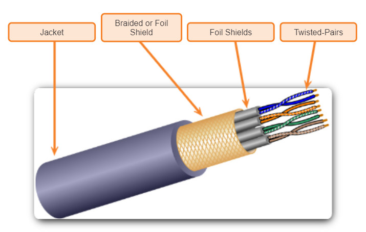
4.2.1.4 Shielded Twisted-Pair (STP) Cable
Shielded twisted-pair (STP) provides better noise protection than UTP cabling. However, compared to UTP cable, STP cable is significantly more expensive and difficult to install. Like UTP cable, STP uses an RJ-45 connector.
STP cable combines the techniques of shielding to counter EMI and RFI and wire twisting to counter crosstalk. To gain the full benefit of the shielding, STP cables are terminated with special shielded STP data connectors. If the cable is improperly grounded, the shield may act like an antenna and pick up unwanted signals.
Different types of STP cables with different characteristics are available. However, there are two common variations of STP:
- STP cable shields the entire bundle of wires with foil eliminating virtually all interference (more common).
- STP cable shields the entire bundle of wires as well as the individual wire pairs with foil eliminating all interference.
The STP cable shown uses four pairs of wires, each wrapped in a foil shield, which are then wrapped in an overall metallic braid or foil.
For many years, STP was the cabling structure specified for use in Token Ring network installations. With the decline of Token Ring the demand for shielded twisted-pair cabling also waned. However, the new 10 GB standard for Ethernet has a provision for the use of STP cabling which is providing a renewed interest in shielded twisted-pair cabling.
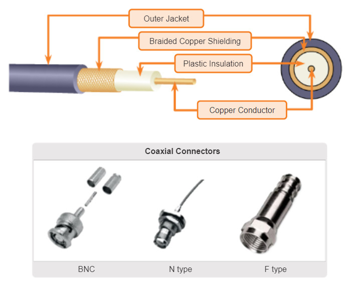
4.2.1.5 Coaxial Cable
Coaxial cable, or coax for short, gets its name from the fact that there are two conductors that share the same axis. As shown in the figure, coaxial cable consists of:
- A copper conductor used to transmit the electronic signals.
- The copper conductor is surrounded by a layer of flexible plastic insulation.
- The insulating material is surrounded in a woven copper braid, or metallic foil, that acts as the second wire in the circuit and as a shield for the inner conductor. This second layer, or shield, also reduces the amount of outside electromagnetic interference.
- The entire cable is covered with a cable jacket to protect it from minor physical damage.
Note: There are different types of connectors used with coax cable.
Coaxial cable was traditionally used in cable television capable of transmitting in one direction. It was also used extensively in early Ethernet installations.
Although UTP cable has essentially replaced coaxial cable in modern Ethernet installations, the coaxial cable design has been adapted for use in:
- Wireless installations: Coaxial cables attach antennas to wireless devices. The coaxial cable carries radio frequency (RF) energy between the antennas and the radio equipment.
- Cable Internet installations: Cable service providers are currently converting their one-way systems to two-way systems to provide Internet connectivity to their customers. To provide these services, portions of the coaxial cable and supporting amplification elements are replaced with fiber-optic cable. However, the final connection to the customer’s location and the wiring inside the customer’s premises is still coax cable. This combined use of fiber and coax is referred to as hybrid fiber coax (HFC).
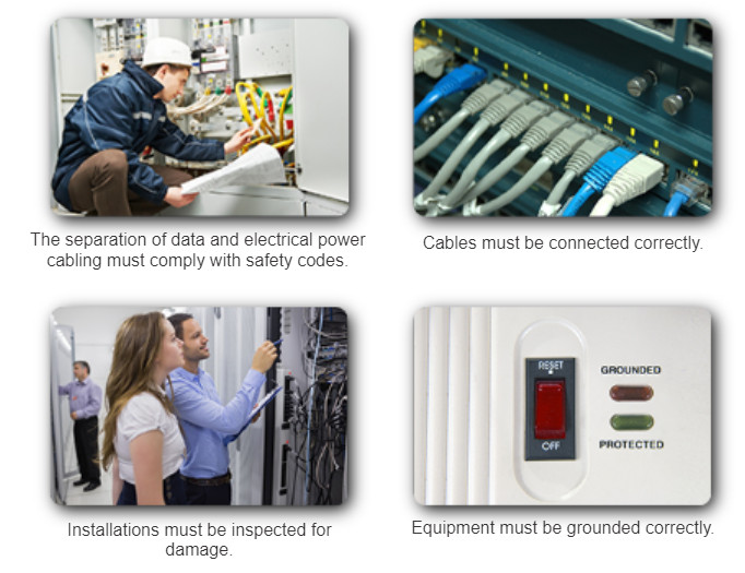
4.2.1.6 Copper Media Safety
All three types of copper media are susceptible to fire and electrical hazards.
Fire hazards exist since cable insulation and sheaths may be flammable or produce toxic fumes when heated or burned. Building authorities or organizations may stipulate related safety standards for cabling and hardware installations.
Electrical hazards are a potential problem since the copper wires could conduct electricity in undesirable ways. This could subject personnel and equipment to a range of electrical hazards. For example, a defective network device could conduct currents to the chassis of other network devices. Additionally, network cabling could present undesirable voltage levels when used to connect devices that have power sources with different ground potentials. Such situations are possible when copper cabling is used to connect networks in different buildings or on different floors of buildings that use different power facilities. Finally, copper cabling may conduct voltages caused by lightning strikes to network devices.
The result of undesirable voltages and currents can include damage to network devices and connected computers, or injury to personnel. It is important that copper cabling be installed appropriately, and according to the relevant specifications and building codes, in order to avoid potentially dangerous and damaging situations.
The figure displays proper cabling practices to avoid potential fire and electrical hazards.
4.2.1.7 Activity – Copper Media Characteristics
4.2.2 UTP Cabling
4.2.2.1 Properties of UTP Cabling
When used as a networking medium, unshielded twisted-pair (UTP) cabling consists of four pairs of color-coded wires that have been twisted together and then encased in a flexible plastic sheath. Network UTP cable has four pairs of either 22- or 24-gauge copper wire. A UTP cable has an external diameter of approximately 0.43 cm (0.17 inches), and its small size can be advantageous during installation.
UTP cable does not use shielding to counter the effects of EMI and RFI. Instead, cable designers have discovered that they can limit the negative effect of crosstalk by:
- Cancellation: Designers now pair wires in a circuit. When two wires in an electrical circuit are placed close together, their magnetic fields are the exact opposite of each other. Therefore, the two magnetic fields cancel each other out and also cancel out any outside EMI and RFI signals.
- Varying the number of twists per wire pair: To further enhance the cancellation effect of paired circuit wires designers vary the number of twists of each wire pair in a cable. UTP cable must follow precise specifications governing how many twists or braids are permitted per meter (3.28 feet) of cable. Notice in the figure that the orange/orange white pairs are twisted less than the blue/white blue pair. Each colored pair is twisted a different number of times.
UTP cable relies solely on the cancellation effect produced by the twisted wire pairs to limit signal degradation and effectively provide self-shielding for wire pairs within the network media.
4.2.2.2 UTP Cabling Standards
UTP cabling conforms to the standards established jointly by the TIA/EIA. Specifically, TIA/EIA-568A stipulates the commercial cabling standards for LAN installations and is the standard most commonly used in LAN cabling environments. Some of the elements defined are:
- Cable types
- Cable lengths
- Connectors
- Cable termination
- Methods of testing cable
The electrical characteristics of copper cabling are defined by the Institute of Electrical and Electronics Engineers (IEEE). IEEE rates UTP cabling according to its performance. Cables are placed into categories according to their ability to carry higher bandwidth rates. For example, Category 5 (Cat5) cable is used commonly in 100BASE-TX FastEthernet installations. Other categories include Enhanced Category 5 (Cat5e) cable, Category 6 (Cat6), and Category 6a.
Cables in higher categories are designed and constructed to support higher data rates. As new gigabit speed Ethernet technologies are being developed and adopted, Cat5e is now the minimally acceptable cable type, with Cat6 being the recommended type for new building installations.
The figure highlights the various categories of UTP cabling.
Note: Some manufacturers are making cables exceeding the TIA/EIA Category 6a specifications and refer to these as Category 7.
4.2.2.3 UTP Connectors
UTP cable is usually terminated with an ISO 8877 specified RJ-45 connector. This connector is used for a range of physical layer specifications, one of which is Ethernet. The TIA/EIA 568 standard describes the wire color codes to pin assignments (pinouts) for Ethernet cables.
The video in Figure 1 displays a UTP cable terminated with an RJ-45 connector.
As shown in Figure 2, the RJ-45 connector is the male component, crimped at the end of the cable. The socket is the female component in a network device, wall, cubicle partition outlet, or patch panel.
Each time copper cabling is terminated there is the possibility of signal loss and the introduction of noise to the communication circuit. When terminated improperly, each cable is a potential source of physical layer performance degradation. It is essential that all copper media terminations be of high quality to ensure optimum performance with current and future network technologies.
Figure 3 displays an example of a badly terminated UTP cable and a well terminated UTP cable.
4.2.2.4 Types of UTP Cable
Different situations may require UTP cables to be wired according to different wiring conventions. This means that the individual wires in the cable have to be connected in different orders to different sets of pins in the RJ-45 connectors.
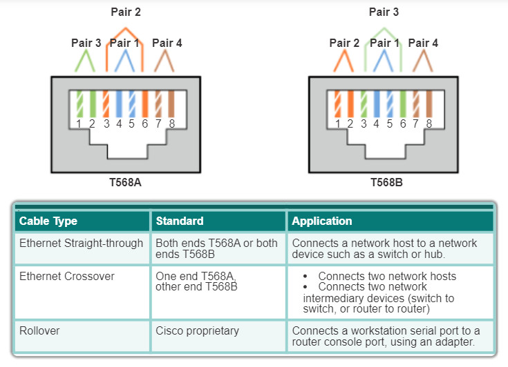
The following are main cable types that are obtained by using specific wiring conventions:
- Ethernet Straight-through: The most common type of networking cable. It is commonly used to interconnect a host to a switch and a switch to a router.
- Ethernet Crossover: An uncommon cable used to interconnect similar devices together. For example to connect a switch to a switch, a host to a host, or a router to a router.
- Rollover: A Cisco proprietary cable used to connect to a router or switch console port.
Using a crossover or straight-through cable incorrectly between devices may not damage the devices, but connectivity and communication between the devices will not take place. This is a common error in the lab and checking that the device connections are correct should be the first troubleshooting action if connectivity is not achieved.
The figure shows the UTP cable type, related standards, and typical application of these cables. It also identifies the individual wire pairs for the TIA 568A and TIA 568B standards.
4.2.2.5 Testing UTP Cables
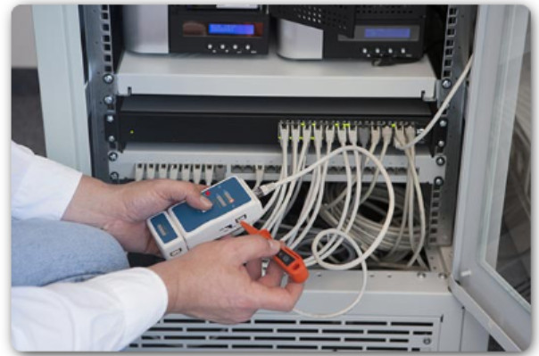
After installation, a UTP cable tester should be used to test for the following parameters:
- Wire map
- Cable length
- Signal loss due to attenuation
- Crosstalk
It is recommended to thoroughly check that all UTP installation requirements are met.
4.2.2.6 Activity – Cable Pinouts
4.2.2.7 Lab – Building an Ethernet Crossover Cable
In this lab, you will complete the following objectives:
- Part 1: Analyze Ethernet Cabling Standards and Pinouts
- Part 2: Build an Ethernet Crossover Cable
- Part 3: Test an Ethernet Crossover Cable
Lab – Building an Ethernet Crossover Cable ./.
4.2.3 Fiber Optic Cabling
4.2.3.1 Properties of Fiber Optic Cabling
Optical fiber cable has become very popular for interconnecting infrastructure network devices. It permits the transmission of data over longer distances and at higher bandwidths (data rates) than any other networking media.
Optical fiber is a flexible but extremely thin transparent strand of very pure glass (silica) not much bigger than a human hair. Bits are encoded on the fiber as light impulses. The fiber-optic cable acts as a waveguide, or “light pipe,” to transmit light between the two ends with minimal loss of signal.
As an analogy, consider an empty paper towel roll with the inside coated like a mirror that is a thousand meters in length and a small laser pointer is used to send Morse code signals at the speed of light. Essentially that is how a fiber-optic cable operates, except that it is smaller in diameter and uses sophisticated light emitting and receiving technologies.
Unlike copper wires, fiber-optic cable can transmit signals with less attenuation and is completely immune to EMI and RFI.
Fiber-optic cabling is now being used in four types of industry:
- Enterprise Networks: Fiber is used for backbone cabling applications and interconnecting infrastructure devices.
- FTTH and Access Networks: Fiber-to-the-home (FTTH) is used to provide always-on broadband services to homes and small businesses. FTTH supports affordable high-speed Internet access, as well as telecommuting, telemedicine, and video on demand.
- Long-Haul Networks: Service providers use long-haul terrestrial optical fiber networks to connect countries and cities. Networks typically range from a few dozen to a few thousand kilometers and use up to 10 Gb/s-based systems.
- Submarine Networks: Special fiber cables are used to provide reliable high-speed, high-capacity solutions capable of or surviving in harsh undersea environments up to transoceanic distances.
Our focus is the use of fiber within the enterprise.
4.2.3.2 Fiber Media Cable Design
Although an optical fiber is very thin, it is composed of two kinds of glass and a protective outer shield. Specifically, these are the:
- Core: Consists of pure glass and is the part of the fiber where light is carried.
- Cladding: The glass that surrounds the core and acts as a mirror. The light pulses propagate down the core while the cladding reflects the light pulses. This keeps the light pulses contained in the fiber core in a phenomenon known as total internal reflection.
- Jacket: Typically a PVC jacket that protects the core and cladding. It may also include strengthening materials and a buffer (coating) whose purpose is to protect the glass from scratches and moisture.
Although susceptible to sharp bends, the properties of the core and cladding have been altered at the molecular level to make it very strong. Optical fiber is proof tested through a rigorous manufacturing process for strength at a minimum of 100,000 pounds per square inch. Optical fiber is durable enough to withstand handling during installation and deployment in harsh environmental conditions in networks all around the world.
4.2.3.3 Types of Fiber Media
Light pulses representing the transmitted data as bits on the media are generated by either:
- Lasers
- Light emitting diodes (LEDs)
Electronic semi-conductor devices called photodiodes detect the light pulses and convert them to voltages that can then be reconstructed into data frames.
Note: The laser light transmitted over fiber-optic cabling can damage the human eye. Care must be taken to avoid looking into the end of an active optical fiber.
Fiber-optic cables can be broadly classified into two types:
- Single-mode fiber (SMF): Consists of a very small core and uses expensive laser technology to send a single ray of light. Popular in long-distance situations spanning hundreds of kilometers such as required in long haul telephony and cable TV applications.
- Multimode fiber (MMF): Consists of a larger core and uses LED emitters to send light pulses. Specifically, light from an LED enters the multimode fiber at different angles. Popular in LANs because they can be powered by low cost LEDs. It provides bandwidth up to 10 Gb/s over link lengths of up to 550 meters.
Figures 1 and 2 highlight the characteristics of multimode and single-mode fiber. One of the highlighted differences between multimode and single-mode fiber is the amount of dispersion. Dispersion refers to the spreading out of a light pulse over time. The more dispersion there is, the greater the loss in signal strength.
[tabs type=”horizontal”]
[tabs_head]
[tab_title]Single Mode[/tab_title]
[tab_title]Multimode[/tab_title]
[/tabs_head]
[tab]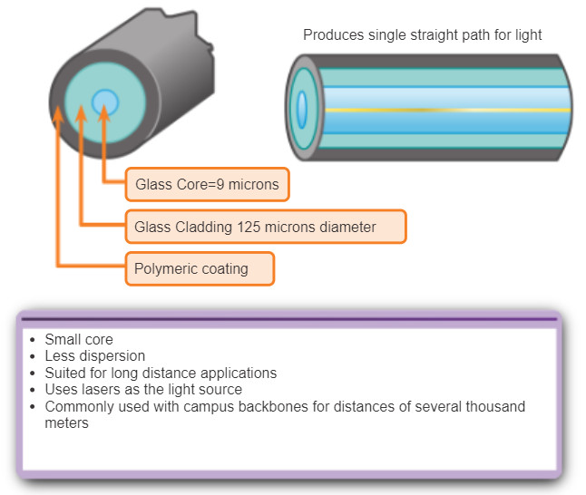 [/tab]
[tab]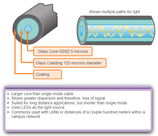 [/tab]
[/tabs]
4.2.3.4 Network Fiber Connectors
An optical fiber connector terminates the end of an optical fiber. A variety of optical fiber connectors are available. The main differences among the types of connectors are dimensions and methods of mechanical coupling. Generally, organizations standardize on one kind of connector, depending on the equipment that they commonly use, or they standardize per type of fiber (one for MMF, one for SMF). Taking into account all the generations of connectors, about 70 connector types are in use today.
As shown in Figure 1, the three most popular network fiber-optic connectors include:
- Straight-Tip (ST): An older bayonet style connector widely used with multimode fiber.
- Subscriber Connector (SC): Sometimes referred to as square connector or standard connector. It is a widely adopted LAN and WAN connector that uses a push-pull mechanism to ensure positive insertion. This connector type is used with multimode and single-mode fiber.
- Lucent Connector (LC): Sometimes called a little or local connector, is quickly growing in popularity due to its smaller size. It is used with single-mode fiber and also supports multimode fiber.
Note: Other fiber connectors such as the Ferrule Connector (FC) and Sub Miniature A (SMA) are not popular in LAN and WAN deployments. Obsolete connectors include biconic (obsolete) and D4 connectors. These connectors are beyond the scope of this chapter.
Because light can only travel in one direction over optical fiber, two fibers are required to support full duplex operation. Therefore, fiber-optic patch cables bundle together two optical fiber cables and terminate them with a pair of standard single fiber connectors. Some fiber connectors accept both the transmitting and receiving fibers in a single connector know as a duplex connector also shown in Figure 1.
Fiber patch cords are required for interconnecting infrastructure devices. For example, Figure 2 displays various common patch cords:
- SC-SC multimode patch cord
- LC-LC single-mode patch cord
- ST-LC multimode patch cord
- SC-ST single-mode patch cord
Fiber cables should be protected with a small plastic cap when not in use.
Also notice the use of color to distinguish between single-mode and multimode patch cords. The reason is because of the TIA-598 standard which recommends the use of a yellow jacket for single-mode fiber cables, and orange (or aqua) for multimode fiber cables.
[tabs type=”horizontal”]
[tabs_head]
[tab_title]Fiber Optic Connectors[/tab_title]
[tab_title]Common Fiber Patch Cords[/tab_title]
[/tabs_head]
[tab]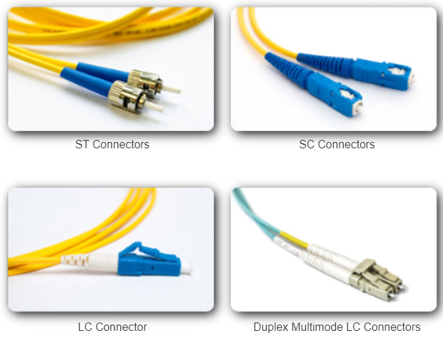 [/tab]
[tab]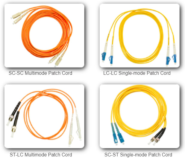 [/tab]
[/tabs]
4.2.3.5 Testing Fiber Cables
Terminating and splicing fiber-optic cabling requires special training and equipment. Incorrect termination of fiber-optic media will result in diminished signaling distances or complete transmission failure.
Three common types of fiber-optic termination and splicing errors are:
- Misalignment: The fiber-optic media are not precisely aligned to one another when joined.
- End gap: The media does not completely touch at the splice or connection.
- End finish: The media ends are not well polished or dirt is present at the termination.
A quick and easy field test can be performed by shining a bright flashlight into one end of the fiber while observing the other end of the fiber. If light is visible, then the fiber is capable of passing light. Although this does not ensure the performance of the fiber, it is a quick and inexpensive way to find a broken fiber.
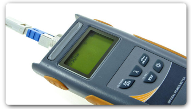
It is recommended that an optical tester such as shown in the figure be used to test fiber-optic cables. An Optical Time Domain Reflectometer (OTDR) can be used to test each fiber-optic cable segment. This device injects a test pulse of light into the cable and measures back scatter and reflection of light detected as a function of time. The OTDR will calculate the approximate distance at which these faults are detected along the length of the cable.
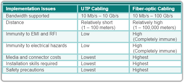
4.2.3.6 Fiber versus Copper
There are many advantages to using fiber-optic cable compared to copper cables.
Given that the fibers used in fiber-optic media are not electrical conductors, the media is immune to electromagnetic interference and will not conduct unwanted electrical currents due to grounding issues. Because optical fibers are thin and have relatively low signal loss, they can be operated at much greater lengths than copper media, without the need for signal regeneration. Some optical fiber physical layer specifications allow lengths that can reach multiple kilometers.
Optical fiber media implementation issues include:
- More expensive (usually) than copper media over the same distance (but for a higher capacity)
- Different skills and equipment required to terminate and splice the cable infrastructure
- More careful handling than copper media
At present, in most enterprise environments, optical fiber is primarily used as backbone cabling for high-traffic point-to-point connections between data distribution facilities and for the interconnection of buildings in multi-building campuses. Because optical fiber does not conduct electricity and has low signal loss, it is well suited for these uses.
The figure highlights some of these differences.
4.2.3.7 Activity – Fiber Optics Terminology
4.2.4 Wireless Media
4.2.4.1 Properties of Wireless Media
Wireless media carry electromagnetic signals that represent the binary digits of data communications using radio or microwave frequencies.
As a networking medium, wireless is not restricted to conductors or pathways, as are copper and fiber media. Wireless media provides the greatest mobility options of all media. As well, the number of wireless enabled devices is continuously increasing. For these reasons, wireless has become the medium of choice for home networks. As network bandwidth options increase, wireless is quickly gaining in popularity in enterprise networks.
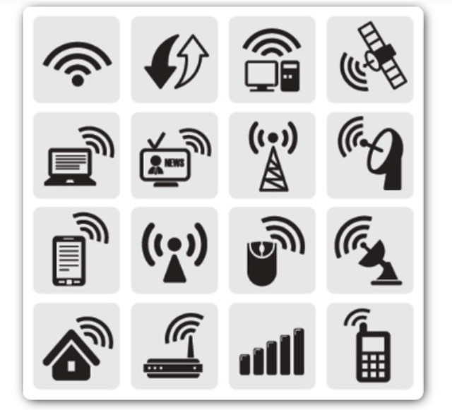
The figure highlights various wireless related symbols.
However, wireless does have some areas of concern including:
- Coverage area: Wireless data communication technologies work well in open environments. However, certain construction materials used in buildings and structures, and the local terrain, will limit the effective coverage.
- Interference: Wireless is susceptible to interference and can be disrupted by such common devices as household cordless phones, some types of fluorescent lights, microwave ovens, and other wireless communications.
- Security: Wireless communication coverage requires no access to a physical strand of media. Therefore, devices and users who are not authorized for access to the network can gain access to the transmission. Consequently, network security is a major component of wireless network administration.
Although wireless is increasing in popularity for desktop connectivity, copper and fiber are the most popular physical layer media for network deployments.
4.2.4.2 Types of Wireless Media
The IEEE and telecommunications industry standards for wireless data communications cover both the data link and physical layers.
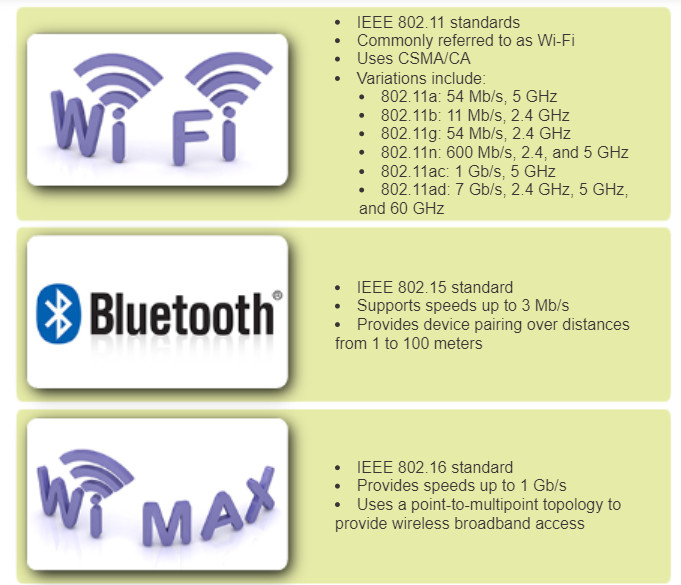
Four common data communications standards that apply to wireless media are:
- Standard IEEE 802.11: Wireless LAN (WLAN) technology, commonly referred to as Wi-Fi, uses a contention or non-deterministic system with a Carrier Sense Multiple Access/Collision Avoidance (CSMA/CA) media access process.
- Standard IEEE 802.15: Wireless Personal Area Network (WPAN) standard, commonly known as “Bluetooth”, uses a device pairing process to communicate over distances from 1 to 100 meters.
- Standard IEEE 802.16: Commonly known as Worldwide Interoperability for Microwave Access (WiMAX), uses a point-to-multipoint topology to provide wireless broadband access.
The figure highlights some of the differences between wireless media.
Note: Other wireless technologies such as cellular and satellite communications can also provide data network connectivity. However, these wireless technologies are out of scope for this chapter.
In each of the above examples, physical layer specifications are applied to areas that include:
- Data to radio signal encoding
- Frequency and power of transmission
- Signal reception and decoding requirements
- Antenna design and construction
Note: Wi-Fi is a trademark of the Wi-Fi Alliance. Wi-Fi is used with certified products that belong to WLAN devices that are based on the IEEE 802.11 standards.
4.2.4.3 Wireless LAN
A common wireless data implementation is enabling devices to wirelessly connect via a LAN. In general, a wireless LAN requires the following network devices:
- Wireless Access Point (AP): Concentrates the wireless signals from users and connects, usually through a copper cable, to the existing copper-based network infrastructure, such as Ethernet. Home and small business wireless routers integrate the functions of a router, switch, and access point into one device as shown in the figure.
- Wireless NIC adapters: Provides wireless communication capability to each network host.
As the technology has developed, a number of WLAN Ethernet-based standards have emerged. Care needs to be taken in purchasing wireless devices to ensure compatibility and interoperability.
The benefits of wireless data communications technologies are evident, especially the savings on costly premises wiring and the convenience of host mobility. However, network administrators need to develop and apply stringent security policies and processes to protect wireless LANs from unauthorized access and damage.
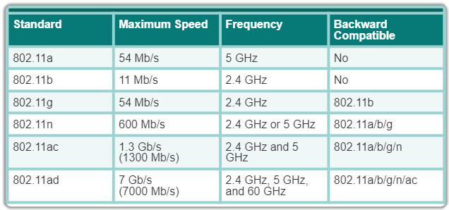
4.2.4.4 802.11 Wi-Fi Standards
Various 802.11 standards have evolved over the years. Standards include:
- IEEE 802.11a: Operates in the 5 GHz frequency band and offers speeds of up to 54 Mb/s. Because this standard operates at higher frequencies, it has a smaller coverage area and is less effective at penetrating building structures. Devices operating under this standard are not interoperable with the 802.11b and 802.11g standards described below.
- IEEE 802.11b: Operates in the 2.4 GHz frequency band and offers speeds of up to 11 Mb/s. Devices implementing this standard have a longer range and are better able to penetrate building structures than devices based on 802.11a.
- IEEE 802.11g: Operates in the 2.4 GHz frequency band and offers speeds of up to 54 Mbps. Devices implementing this standard therefore operate at the same radio frequency and range as 802.11b but with the bandwidth of 802.11a.
- IEEE 802.11n: Operates in the 2.4 GHz or 5 GHz frequency bands. The typical expected data rates are 100 Mb/s to 600 Mb/s with a distance range of up to 70 meters. It is backward compatible with 802.11a/b/g devices.
- IEEE 802.11ac: Can simultaneously operate in the 2.4 GHz and 5.5 GHz frequency bands providing data rates up to 450 Mb/s and 1.3 Gb/s (1300 Mb/s.) It is backward compatible with 802.11a/b/g/n devices.
- IEEE 802.11ad: Also known as “WiGig”. It uses a tri-band Wi-Fi solution using 2.4 GHz, 5 GHz, and 60 GHz and offers theoretical speeds of up to 7 Gb/s.
The figure highlights some of these differences.
4.2.4.5 Packet Tracer – Connecting a Wired and Wireless LAN
When working in Packet Tracer (a lab environment or a corporate setting), you should know how to select the appropriate cable and how to properly connect devices. This activity will examine device configurations in Packet Tracer, selecting the proper cable based on the configuration, and connecting the devices. This activity will also explore the physical view of the network in Packet Tracer.
Packet Tracer – Connecting a Wired and Wireless LAN Instructions ./.
Packet Tracer – Connecting a Wired and Wireless LAN – PKA ./.
4.2.4.6 Lab – Viewing Wired and Wireless NIC Information
In this lab, you will complete the following objectives:
- Part 1: Identify and Work with PC NICs
- Part 2: Identify and Use the System Tray Network Icons
Lab – Viewing Wired and Wireless NIC Information ./.
4.3 Data Link Layer Protocols
4.3.1 Purpose of the Data Link Layer
4.3.1.1 The Data Link Layer
The TCP/IP network access layer is the equivalent of the OSI:
- Data link (Layer 2)
- Physical (Layer 1)
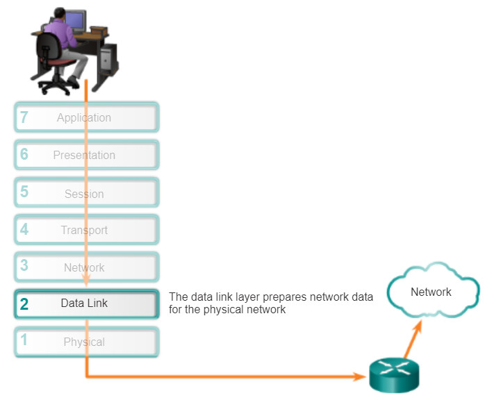
As shown in the figure, the data link layer is responsible for the exchange of frames between nodes over a physical network media. It allows the upper layers to access the media and controls how data is placed and received on the media.
Note: The Layer 2 notation for network devices connected to a common medium is called a node.
Specifically the data link layer performs these two basic services:
- It accepts Layer 3 packets and packages them into data units called frames.
- It controls media access control and performs error detection.
The data link layer effectively separates the media transitions that occur as the packet is forwarded from the communication processes of the higher layers. The data link layer receives packets from and directs packets to an upper layer protocol, in this case IPv4 or IPv6. This upper layer protocol does not need to be aware of which media the communication will use.
Note: In this chapter, media and medium do not refer to digital content and multimedia such as audio, animation, television, and video. Media refers to the material that actually carries the data signals, such as copper cable and optical fiber.
4.3.1.2 Data Link Sublayers
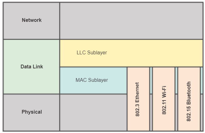
The data link layer is actually divided into two sublayers:
- Logical Link Control (LLC): This upper sublayer defines the software processes that provide services to the network layer protocols. It places information in the frame that identifies which network layer protocol is being used for the frame. This information allows multiple Layer 3 protocols, such as IPv4 and IPv6, to utilize the same network interface and media.
- Media Access Control (MAC): This lower sublayer defines the media access processes performed by the hardware. It provides data link layer addressing and delimiting of data according to the physical signaling requirements of the medium and the type of data link layer protocol in use.
Separating the data link layer into sublayers allows for one type of frame defined by the upper layer to access different types of media defined by the lower layer. Such is the case in many LAN technologies, including Ethernet.
The figure illustrates how the data link layer is separated into the LLC and MAC sublayers. The LLC communicates with the network layer while the MAC sublayer allows various network access technologies. For instance, the MAC sublayer communicates with Ethernet LAN technology to send and receive frames over copper or fiber-optic cable. The MAC sublayer also communicates with wireless technologies such as Wi-Fi and Bluetooth to send and receive frames wirelessly.
4.3.1.3 Media Access Control
Layer 2 protocols specify the encapsulation of a packet into a frame and the techniques for getting the encapsulated packet on and off each medium. The technique used for getting the frame on and off media is called the media access control method.
As packets travel from source host to destination host, they typically traverse over different physical networks. These physical networks can consist of different types of physical media such as copper wires, optical fibers, and wireless consisting of electromagnetic signals, radio and microwave frequencies, and satellite links.
The packets do not have a way to directly access these different media. It is the role of the OSI data link layer to prepare network layer packets for transmission and to control access to the physical media. The media access control methods described by the data link layer protocols define the processes by which network devices can access the network media and transmit frames in diverse network environments.
Without the data link layer, network layer protocols such as IP, would have to make provisions for connecting to every type of media that could exist along a delivery path. Moreover, IP would have to adapt every time a new network technology or medium was developed. This process would hamper protocol and network media innovation and development. This is a key reason for using a layered approach to networking.
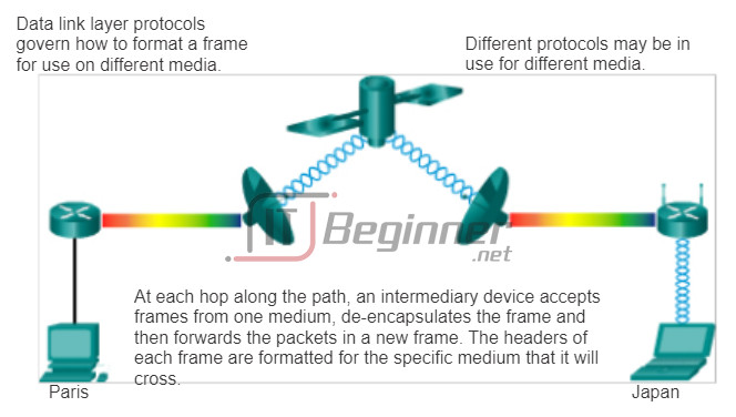
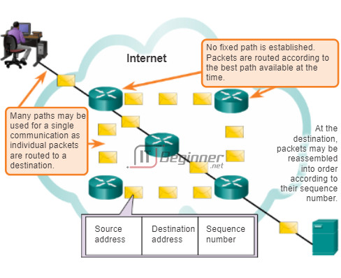
The animation in the figure provides an example of a PC in Paris connecting to a laptop in Japan. Although the two hosts are communicating using IP exclusively, it is likely that numerous data link layer protocols are being used to transport the IP packets over various types of LANs and WANs. Each transition at a router may require a different data link layer protocol for transport on a new medium.
4.3.1.4 Providing Access to Media
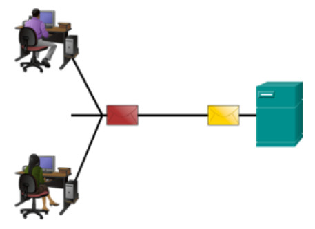
Different media access control methods may be required during the course of a single communication. Each network environment that packets encounter as they travel from a local host to a remote host can have different characteristics. For example, an Ethernet LAN consists of many hosts contending to access the network medium on an ad hoc basis. Serial links consist of a direct connection between only two devices over which data flows sequentially as bits in an orderly way.
Router interfaces encapsulate the packet into the appropriate frame, and a suitable media access control method is used to access each link. In any given exchange of network layer packets, there may be numerous data link layer and media transitions. At each hop along the path, a router:
- Accepts a frame from a medium
- De-encapsulates the frame
- Re-encapsulates the packet into a new frame
- Forwards the new frame appropriate to the medium of that segment of the physical network
The router in the figure has an Ethernet interface to connect to the LAN and a serial interface to connect to the WAN. As the router processes frames, it will use data link layer services to receive the frame from one medium, de-encapsulate it to the Layer 3 PDU, re-encapsulate the PDU into a new frame, and place the frame on the medium of the next link of the network.
![]()
4.3.2 Layer 2 Frame Structure
4.3.2.1 Formatting Data for Transmission
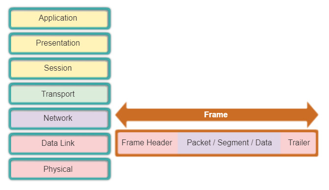
The data link layer prepares a packet for transport across the local media by encapsulating it with a header and a trailer to create a frame. The description of a frame is a key element of each data link layer protocol.
Data link layer protocols require control information to enable the protocols to function. Control information typically answers:
- Which nodes are in communication with each other?
- When does communication between individual nodes begin and when does it end?
- Which errors occurred while the nodes communicated?
- Which nodes will communicate next?
Unlike the other PDUs that have been discussed in this course, the data link layer frame includes:
- Header: Contains control information, such as addressing, and is located at the beginning of the PDU.
- Data: Contains the IP header, transport layer header, and application data.
- Trailer: Contains control information for error detection added to the end of the PDU.
These frame elements are shown in the figure, and will be discussed in greater detail.
4.3.2.2 Creating a Frame
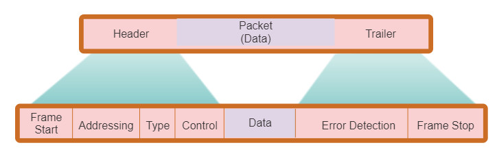
When data travels on the media, it is converted into a stream of bits, or 1s and 0s. If a node is receiving long streams of bits, how does it determine where a frame starts and stops or which bits represent the address?
Framing breaks the stream into decipherable groupings, with control information inserted in the header and trailer as values in different fields. This format gives the physical signals a structure that can be received by nodes and decoded into packets at the destination.
As shown in the figure, generic frame field types include:
- Frame start and stop indicator flags: Used by the MAC sublayer to identify the beginning and end limits of the frame.
- Addressing: Used by the MAC sublayer to identify the source and destination nodes.
- Type: Used by the LLC to identify the Layer 3 protocol.
- Control: Identifies special flow control services.
- Data: Contains the frame payload (i.e., packet header, segment header, and the data).
- Error Detection: Included after the data to form the trailer, these frame fields are used for error detection.
Not all protocols include all of these fields. The standards for a specific data link protocol define the actual frame format.
Note: Examples of frame formats will be discussed at the end of this chapter.
4.3.2.3 Activity – Generic Frame Fields
4.3.3 Layer 2 Standards
4.3.3.1 Data Link Layer Standards
Unlike the protocols of the upper layers of the TCP/IP suite, data link layer protocols are generally not defined by Request for Comments (RFCs). Although the Internet Engineering Task Force (IETF) maintains the functional protocols and services for the TCP/IP protocol suite in the upper layers, the IETF does not define the functions and operation of that model’s network access layer.
Specifically the data link layer services and specifications are defined by multiple standards based on a variety of technologies and media to which the protocols are applied. Some of these standards integrate both Layer 2 and Layer 1 services.
The functional protocols and services at the data link layer are described by:
- Engineering organizations which set public and open standards and protocols.
- Communications companies which set and use proprietary protocols to take advantage of new advances in technology or market opportunities.
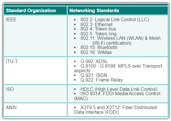
Engineering organizations that define open standards and protocols that apply to the data link layer include:
- Institute of Electrical and Electronics Engineers (IEEE)
- International Telecommunication Union (ITU)
- International Organization for Standardization (ISO)
- American National Standards Institute (ANSI)
The table in the figure highlights various standard organizations and some of their more important data link layer protocols.
4.3.3.2 Activity – Data Link Layer Standards Organizations
4.4 Media Access Control
4.4.1 Topologies
4.4.1.1 Controlling Access to the Media
Regulating the placement of data frames onto the media is controlled by the media access control sublayer.
Media access control is the equivalent of traffic rules that regulate the entrance of motor vehicles onto a roadway. The absence of any media access control would be the equivalent of vehicles ignoring all other traffic and entering the road without regard to the other vehicles. However, not all roads and entrances are the same. Traffic can enter the road by merging, by waiting for its turn at a stop sign, or by obeying signal lights. A driver follows a different set of rules for each type of entrance.
In the same way, there are different ways to regulate placing frames onto the media. The protocols at the data link layer define the rules for access to different media. Some media access control methods use highly-controlled processes to ensure that frames are safely placed on the media. These methods are defined by sophisticated protocols, which require mechanisms that introduce overhead onto the network.
Among the different implementations of the data link layer protocols, there are different methods of controlling access to the media. These media access control techniques define if and how the nodes share the media.
The actual media access control method used depends on:
- Topology: How the connection between the nodes appears to the data link layer.
- Media sharing: How the nodes share the media. The media sharing can be point-to-point such as in WAN connections or shared such as in LAN networks.
4.4.1.2 Physical and Logical Topologies
The topology of a network is the arrangement or relationship of the network devices and the interconnections between them. LAN and WAN topologies can be viewed in two ways:
- Physical topology: Refers to the physical connections and identifies how end devices and infrastructure devices such as routers, switches, and wireless access points are interconnected. Physical topologies are usually point-to-point or star. See Figure 1.
- Logical topology: Refers to the way a network transfers frames from one node to the next. This arrangement consists of virtual connections between the nodes of a network. These logical signal paths are defined by data link layer protocols. The logical topology of point-to-point links is relatively simple while shared media offers deterministic and a non-deterministic media access control methods. See Figure 2.
The data link layer “sees” the logical topology of a network when controlling data access to the media. It is the logical topology that influences the type of network framing and media access control used.
[tabs type=”horizontal”]
[tabs_head]
[tab_title]Physical Topology[/tab_title]
[tab_title]Logical Topology[/tab_title]
[/tabs_head]
[tab]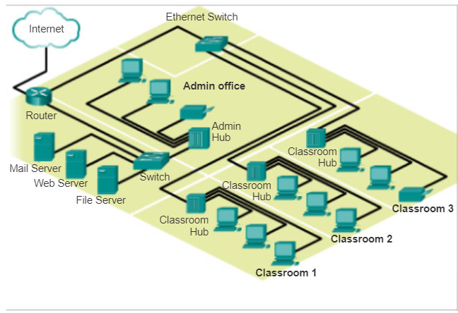 [/tab]
[tab] [/tab]
[/tabs]
4.4.2 WAN Topologies
4.4.2.1 Common Physical WAN Topologies
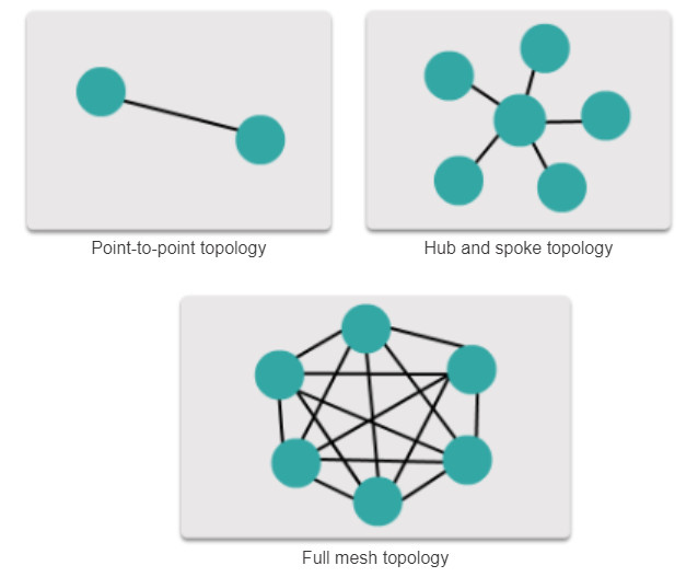
WANs are commonly interconnected using the following physical topologies:
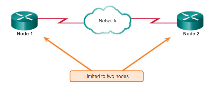
- Point-to-Point: This is the simplest topology which consists of a permanent link between two endpoints. For this reason, this is a very popular WAN topology.
- Hub and Spoke: A WAN version of the star topology in which a central site interconnects branch sites using point-to-point links.
- Mesh: This topology provides high availability, but requires that every end system be interconnected to every other system. Therefore the administrative and physical costs can be significant. Each link is essentially a point-to-point link to the other node. Variations of this topology include a partial mesh where some but not all of end devices are interconnected.
The three common physical WAN topologies are illustrated in the figure.
4.4.2.2 Physical Point-to-Point Topology
Physical point-to-point topologies directly connect two nodes as shown in the figure.
In this arrangement, two nodes do not have to share the media with other hosts. Additionally, a node does not have to make any determination about whether an incoming frame is destined for it or another node. Therefore, the logical data link protocols can be very simple as all frames on the media can only travel to or from the two nodes. The frames are placed on the media by the node at one end and taken off the media by the node at the other end of the point-to-point circuit.
Data link layer protocols could provide more sophisticated media access control processes for logical point-to-point topologies, but this would only add unnecessary protocol overhead.
4.4.2.3 Logical Point-to-Point Topology
The end nodes communicating in a point-to-point network can be physically connected via a number of intermediate devices. However, the use of physical devices in the network does not affect the logical topology.
As shown in Figure 1, the source and destination node may be indirectly connected to each other over some geographical distance. In some cases, the logical connection between nodes forms what is called a virtual circuit. A virtual circuit is a logical connection created within a network between two network devices. The two nodes on either end of the virtual circuit exchange the frames with each other. This occurs even if the frames are directed through intermediary devices. Virtual circuits are important logical communication constructs used by some Layer 2 technologies.
The media access method used by the data link protocol is determined by the logical point-to-point topology, not the physical topology. This means that the logical point-to-point connection between two nodes may not necessarily be between two physical nodes at each end of a single physical link.
Figure 2 shows the physical devices in-between the two routers.
[tabs type=”horizontal”]
[tabs_head]
[tab_title]Logical Connection[/tab_title]
[tab_title]Logical Point-to-Point Topology[/tab_title]
[/tabs_head]
[tab]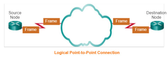 [/tab]
[tab]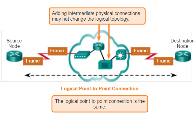 [/tab]
[/tabs]
4.4.2.4 Half and Full Duplex
Figure 1 shows a point-to-point topology. In point-to-point networks, data can flow in one of two ways:
- Half-duplex communication: Both devices can both transmit and receive on the media but cannot do so simultaneously. Ethernet has established arbitration rules for resolving conflicts arising from instances when more than one station attempts to transmit at the same time. Figure 2 shows half-duplex communication.
- Full-duplex communication: Both devices can transmit and receive on the media at the same time. The data link layer assumes that the media is available for transmission for both nodes at any time. Therefore, there is no media arbitration necessary in the data link layer. Figure 3 shows full-duplex communication.
[tabs type=”horizontal”]
[tabs_head]
[tab_title]Point-to-Point Connection[/tab_title]
[tab_title]Half-Duplex Commmunication[/tab_title]
[tab_title]Full-Duplex Commmunication[/tab_title]
[/tabs_head]
[tab]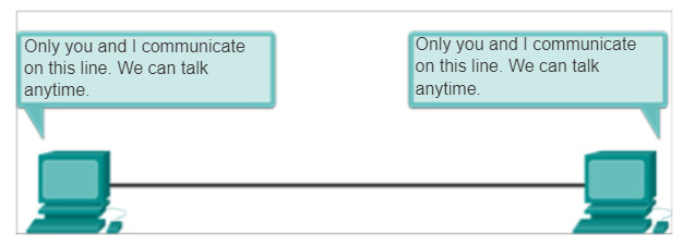 [/tab]
[tab] [/tab]
[tab] [/tab]
[/tabs]
4.4.3 LAN Topologies
4.4.3.1 Physical LAN Topologies
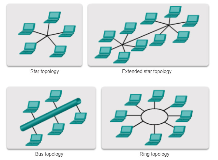
Physical topology defines how the end systems are physically interconnected. In shared media LANs, end devices can be interconnected using the following physical topologies:
- Star: End devices are connected to a central intermediate device. Early star topologies interconnected end devices using hubs. However, star topologies now use switches. The star topology is the most common physical LAN topology primarily because it is easy to install, very scalable (easy to add and remove end devices), and easy to troubleshoot.
- Extended star or hybrid: This is a combination of the other topologies such as star networks interconnected to each other using a bus topology.
- Bus: All end systems are chained to each other and terminated in some form on each end. Infrastructure devices such as switches are not required to interconnect the end devices. Bus topologies were used in legacy Ethernet networks because it was inexpensive to use and easy to set up.
- Ring: End systems are connected to their respective neighbor forming a ring. Unlike the bus topology, the ring does not need to be terminated. Ring topologies were used in legacy Fiber Distributed Data Interface (FDDI) networks. Specifically, FDDI networks employ a second ring for fault tolerance or performance enhancements.
The figure illustrates how end devices are interconnected on LANs.
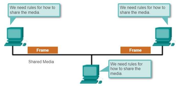
4.4.3.2 Logical Topology for Shared Media
Logical topology of a network is closely related to the mechanism used to manage network access. Access methods provide the procedures to manage network access so that all stations have access. When several entities share the same media, some mechanism must be in place to control access. Access methods are applied to networks to regulate this media access.
Some network topologies share a common medium with multiple nodes. At any one time, there may be a number of devices attempting to send and receive data using the network media. There are rules that govern how these devices share the media.
There are two basic media access control methods for shared media:
- Contention-based access: All nodes compete for the use of the medium but have a plan if there are collisions. Figure 1 shows contention-based access.
- Controlled access: Each node has its own time to use the medium. Figure 2 shows controlled access.
The data link layer protocol specifies the media access control method that will provide the appropriate balance between frame control, frame protection, and network overhead.
[tabs type=”horizontal”]
[tabs_head]
[tab_title]Contention-Based Access[/tab_title]
[tab_title]Controlled Access[/tab_title]
[/tabs_head]
[tab]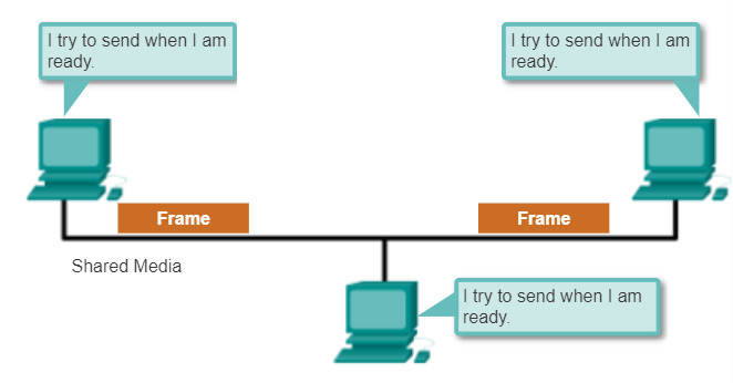 [/tab]
[tab]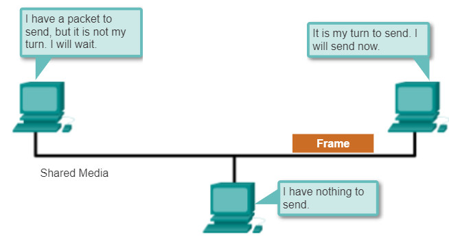 [/tab]
[/tabs]
4.4.3.3 Contention-Based Access
When using a non-deterministic contention-based method, a network device can attempt to access the medium whenever it has data to send. To prevent complete chaos on the media, these methods use a Carrier Sense Multiple Access (CSMA) process to first detect if the media is carrying a signal.
If a carrier signal on the media from another node is detected, it means that another device is transmitting. When the device attempting to transmit sees that the media is busy, it will wait and try again after a short time period. If no carrier signal is detected, the device transmits its data. Ethernet and wireless networks use contention-based media access control.
It is possible that the CSMA process will fail and two devices will transmit at the same time creating a data collision. If this occurs, the data sent by both devices will be corrupted and will need to be resent.
Contention-based media access control methods do not have the overhead of controlled access methods. A mechanism for tracking whose turn it is to access the media is not required. However, the contention-based systems do not scale well under heavy media use. As use and the number of nodes increases, the probability of successful media access without a collision decreases. Additionally, the recovery mechanisms required to correct errors due to these collisions further diminishes the throughput.
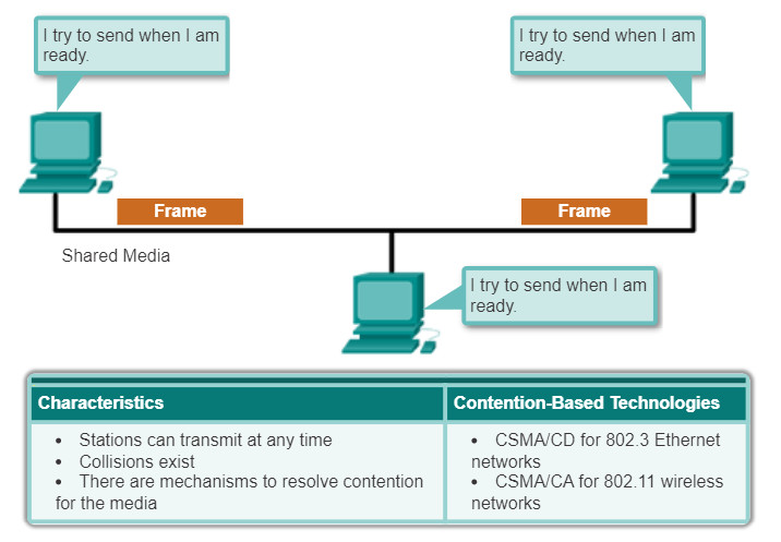
CSMA is usually implemented in conjunction with a method for resolving the media contention. The two commonly used methods are:
- Carrier sense multiple access with collision detection (CSMA/CD): The end device monitors the media for the presence of a data signal. If a data signal is absent and therefore the media is free, the device transmits the data. If signals are then detected that show another device was transmitting at the same time, all devices stop sending and try again later. Traditional forms of Ethernet use this method.
- Carrier sense multiple access with collision avoidance (CSMA/CA): The end device examines the media for the presence of a data signal. If the media is free, the device sends a notification across the media of its intent to use it. Once it receives a clearance to transmit, the device then sends the data. This method is used by 802.11 wireless networking technologies.
The figure illustrates the following:
- How contention-based access methods operates
- Characteristics of contention-based access methods
- Examples of contention-based access methods
4.4.3.4 Multi-Access Topology
A logical multi-access topology enables a number of nodes to communicate by using the same shared media. Data from only one node can be placed on the medium at any one time. Every node sees all the frames that are on the medium, but only the node to which the frame is addressed processes the contents of the frame.
Having many nodes share access to the medium requires a data link media access control method to regulate the transmission of data and thereby reduce collisions between different signals.
Play the animation to see how nodes access the media in a multi-access topology.
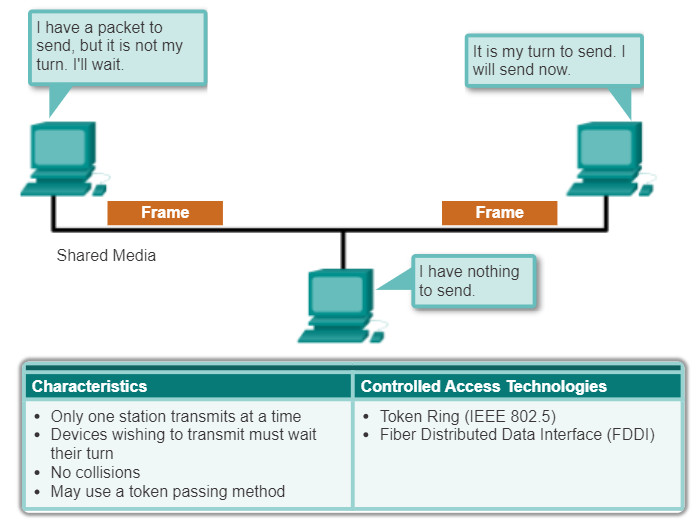
4.4.3.5 Controlled Access
When using the controlled access method, network devices take turns, in sequence, to access the medium. If an end device does not need to access the medium, then the opportunity passes to the next end device. This process is facilitated by use of a token. An end device acquires the token and places a frame on the media, no other device can do so until the frame has arrived and been processed at the destination, releasing the token.
Note: This method is also known as scheduled access or deterministic.
Although controlled access is well-ordered and provides predictable throughput, deterministic methods can be inefficient because a device has to wait for its turn before it can use the medium.
Controlled access examples include:
- Token Ring (IEEE 802.5)
- Fiber Distributed Data Interface (FDDI) which is based on the IEEE 802.4 token bus protocol.
Note: Both of these media access control methods are considered obsolete.
The figure illustrates the following:
- How controlled access methods operate
- Characteristics of controlled access methods
- Examples of controlled access methods
4.4.3.6 Ring Topology
In a logical ring topology, each node in turn receives a frame. If the frame is not addressed to the node, the node passes the frame to the next node. This allows a ring to use a controlled media access control technique called token passing.
Nodes in a logical ring topology remove the frame from the ring, examine the address, and send it on if it is not addressed for that node. In a ring, all nodes around the ring (between the source and destination node) examine the frame.
There are multiple media access control techniques that could be used with a logical ring, depending on the level of control required. For example, only one frame at a time is usually carried by the media. If there is no data being transmitted, a signal (known as a token) may be placed on the media and a node can only place a data frame on the media when it has the token.
Remember that the data link layer “sees” a logical ring topology. The actual physical cabling topology could be another topology.
Play the animation to see how nodes access the media in a logical ring topology.
4.4.3.7 Activity – Logical and Physical Topologies
4.4.4 Data Link Frame
4.4.4.1 The Frame
Although there are many different data link layer protocols that describe data link layer frames, each frame type has three basic parts:
- Header
- Data
- Trailer
All data link layer protocols encapsulate the Layer 3 PDU within the data field of the frame. However, the structure of the frame and the fields contained in the header and trailer vary according to the protocol.
The data link layer protocol describes the features required for the transport of packets across different media. These features of the protocol are integrated into the encapsulation of the frame. When the frame arrives at its destination and the data link protocol takes the frame off the media, the framing information is read and discarded.
There is no one frame structure that meets the needs of all data transportation across all types of media. Depending on the environment, the amount of control information needed in the frame varies to match the media access control requirements of the media and logical topology.
As shown in Figure 1, a fragile environment requires more control. However, a protected environment, as shown in Figure 2, requires fewer controls.
[tabs type=”horizontal”]
[tabs_head]
[tab_title]Fragile Environment[/tab_title]
[tab_title]Protected Environment[/tab_title]
[/tabs_head]
[tab]
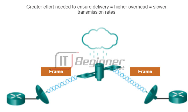
[/tab]
[tab]
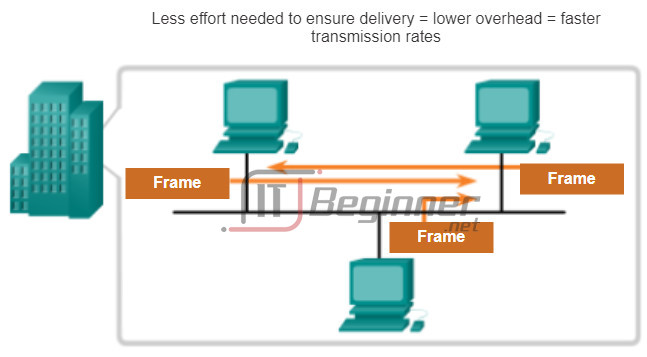
[/tab]
[/tabs]
4.4.4.2 The Header
The frame header contains the control information specified by the data link layer protocol for the specific logical topology and media used.
Frame control information is unique to each type of protocol. It is used by the Layer 2 protocol to provide features demanded by the communication environment.
The figure displays the Ethernet frame header fields:
- Start Frame field: Indicates the beginning of the frame.
- Source and Destination Address fields: Indicates the source and destination nodes on the media.
- Type field: Indicates the upper layer service contained in the frame.
Different data link layer protocols may use different fields from those mentioned. For example other Layer 2 protocol header frame fields could include:
- Priority/Quality of Service field: Indicates a particular type of communication service for processing.
- Logical connection control field: Used to establish a logical connection between nodes.
- Physical link control field: Used to establish the media link.
- Flow control field: Used to start and stop traffic over the media.
- Congestion control field: Indicates congestion in the media.
Because the purposes and functions of data link layer protocols are related to the specific topologies and media, each protocol has to be examined to gain a detailed understanding of its frame structure. As protocols are discussed in this course, more information about the frame structure will be explained.
4.4.4.3 Layer 2 Address
The data link layer provides addressing that is used in transporting a frame across a shared local media. Device addresses at this layer are referred to as physical addresses. Data link layer addressing is contained within the frame header and specifies the frame destination node on the local network. The frame header may also contain the source address of the frame.
Unlike Layer 3 logical addresses, which are hierarchical, physical addresses do not indicate on what network the device is located. Rather, the physical address is a unique device specific address. If the device is moved to another network or subnet, it will still function with the same Layer 2 physical address.
An address that is device-specific and non-hierarchical cannot be used to locate a device across large networks or the Internet. This would be like trying to find a single house within the entire world, with nothing more than a house number and street name. The physical address, however, can be used to locate a device within a limited area. For this reason, the data link layer address is only used for local delivery. Addresses at this layer have no meaning beyond the local network. Compare this to Layer 3, where addresses in the packet header are carried from source host to destination host regardless of the number of network hops along the route.
If the data must pass onto another network segment, an intermediate device, such as a router, is necessary. The router must accept the frame based on the physical address and de-encapsulate the frame in order to examine the hierarchical address, or IP address. Using the IP address, the router is able to determine the network location of the destination device and the best path to reach it. Once it knows where to forward the packet, the router then creates a new frame for the packet, and the new frame is sent onto the next segment toward its final destination.
The figure highlights Layer 2 address requirements in multi-access and point-to-point topologies.
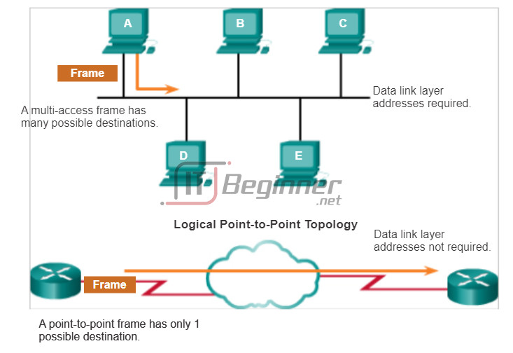
4.4.4.4 The Trailer
Data link layer protocols add a trailer to the end of each frame. The trailer is used to determine if the frame arrived without error. This process is called error detection and is accomplished by placing a logical or mathematical summary of the bits that comprise the frame in the trailer. Error detection is added at the data link layer because the signals on the media could be subject to interference, distortion, or loss that would substantially change the bit values that those signals represent.
A transmitting node creates a logical summary of the contents of the frame. This is known as the cyclic redundancy check (CRC) value. This value is placed in the Frame Check Sequence (FCS) field of the frame to represent the contents of the frame.
Click the FCS and Stop Frame fields in the figure for more information.
When the frame arrives at the destination node, the receiving node calculates its own logical summary, or CRC, of the frame. The receiving node compares the two CRC values. If the two values are the same, the frame is considered to have arrived as transmitted. If the CRC value in the FCS differs from the CRC calculated at the receiving node, the frame is discarded.
Therefore, the FCS field is used to determine if errors occurred in the transmission and reception of the frame. The error detection mechanism provided by the use of the FCS field discovers most errors caused on the media.
There is always the small possibility that a frame with a good CRC result is actually corrupt. Errors in bits may cancel each other out when the CRC is calculated. Upper layer protocols would then be required to detect and correct this data loss.
4.4.4.5 LAN and WAN Frames
In a TCP/IP network, all OSI Layer 2 protocols work with the IP at OSI Layer 3. However, the actual Layer 2 protocol used depends on the logical topology of the network and the implementation of the physical layer. Given the wide range of physical media used across the range of topologies in networking, there are a correspondingly high number of Layer 2 protocols in use.
Each protocol performs media access control for specified Layer 2 logical topologies. This means that a number of different network devices can act as nodes that operate at the data link layer when implementing these protocols. These devices include the network adapter or network interface cards (NICs) on computers as well as the interfaces on routers and Layer 2 switches.
The Layer 2 protocol used for a particular network topology is determined by the technology used to implement that topology. The technology is, in turn, determined by the size of the network – in terms of the number of hosts and the geographic scope – and the services to be provided over the network.
A LAN typically uses a high bandwidth technology that is capable of supporting large numbers of hosts. A LAN’s relatively small geographic area (a single building or a multi-building campus) and its high density of users make this technology cost effective.
However, using a high bandwidth technology is usually not cost-effective for WANs that cover large geographic areas (cities or multiple cities, for example). The cost of the long distance physical links and the technology used to carry the signals over those distances typically results in lower bandwidth capacity.
Difference in bandwidth normally results in the use of different protocols for LANs and WANs.
Common data link layer protocols include:
- Ethernet
- Point-to-Point Protocol (PPP)
- 802.11 Wireless
Other protocols covered in the CCNA curriculum are High-Level Data Link Control (HDLC) and Frame Relay.
Click Play to see examples of Layer 2 protocols.
4.4.4.6 Ethernet Frame
Ethernet is the dominant LAN technology. It is a family of networking technologies that are defined in the IEEE 802.2 and 802.3 standards.
Ethernet standards define both the Layer 2 protocols and the Layer 1 technologies. Ethernet is the most widely used LAN technology and supports data bandwidths of 10 Mbps, 100 Mbps, 1 Gbps (1,000 Mbps), or 10 Gbps (10,000 Mbps).
The basic frame format and the IEEE sublayers of OSI Layers 1 and 2 remain consistent across all forms of Ethernet. However, the methods for detecting and placing data on the media vary with different implementations.
Ethernet provides unacknowledged connectionless service over a shared media using CSMA/CD as the media access methods. Shared media requires that the Ethernet frame header use a data link layer address to identify the source and destination nodes. As with most LAN protocols, this address is referred to as the MAC address of the node. An Ethernet MAC address is 48 bits and is generally represented in hexadecimal format.
The figure shows the many fields of the Ethernet frame. At the data link layer, the frame structure is nearly identical for all speeds of Ethernet. However, at the physical layer, different versions of Ethernet place the bits onto the media differently. Ethernet is discussed in more detail in the next chapter.
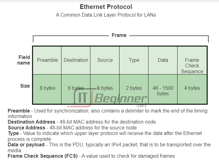
4.4.4.7 PPP Frame
Another data link layer protocol is the Point-to-Point Protocol (PPP). PPP is a protocol used to deliver frames between two nodes. Unlike many data link layer protocols that are defined by electrical engineering organizations, the PPP standard is defined by RFCs. PPP was developed as a WAN protocol and remains the protocol of choice to implement many serial WANs. PPP can be used on various physical media, including twisted pair, fiber-optic lines, and satellite transmission, as well as for virtual connections.
PPP uses a layered architecture. To accommodate the different types of media, PPP establishes logical connections, called sessions, between two nodes. The PPP session hides the underlying physical media from the upper PPP protocol. These sessions also provide PPP with a method for encapsulating multiple protocols over a point-to-point link. Each protocol encapsulated over the link establishes its own PPP session.
PPP also allows the two nodes to negotiate options within the PPP session. This includes authentication, compression, and multilink (the use of multiple physical connections).
Refer to the figure for the basic fields in a PPP frame.
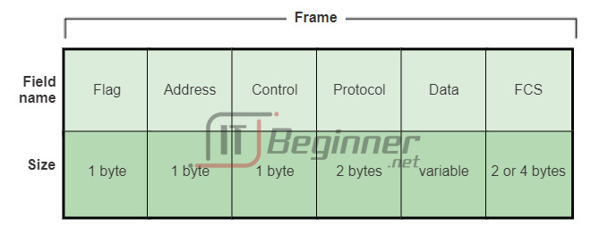
Flag – A single byte that indicates the beginning or end of a frame. The flag field consists of the binary sequence 01111110.
Address – A single byte that contains the standard PPP broadcast address. PPP does not assign individual station addresses.
Control – A single byte that contains the binary sequence 00000011, which calls for transmission of user data in an unsequenced frame.
Protocol – Two bytes that identify the protocol encapsulated in the data field of the frame. The most up-to-date values of the protocol field are specified in the most recent Assigned Numbers Request For Comments (RFC).
Data – Zero or more bytes that contain the datagram for the protocol specified in the protocol field.
Frame Check Sequence (FCS) – Normally 16 bits (2 bytes). By prior agreement, consenting PPP implementations can use a 32-bit (4-byte) FCS for improved error detection.
4.4.4.8 802.11 Wireless Frame
The IEEE 802.11 standard uses the same 802.2 LLC and 48-bit addressing scheme as other 802 LANs. However, there are many differences at the MAC sublayer and physical layer. In a wireless environment, the environment requires special considerations. There is no definable physical connectivity; therefore, external factors may interfere with data transfer and it is difficult to control access. To meet these challenges, wireless standards have additional controls.
The IEEE 802.11 standard is commonly referred to as Wi-Fi. It is a contention-based system using a CSMA/CA media access process. CSMA/CA specifies a random backoff procedure for all nodes that are waiting to transmit. The most likely opportunity for medium contention is just after the medium becomes available. Making the nodes back off for a random period greatly reduces the likelihood of a collision.
802.11 networks also use data link acknowledgements to confirm that a frame is received successfully. If the sending station does not detect the acknowledgement frame, either because the original data frame or the acknowledgment was not received intact, the frame is retransmitted. This explicit acknowledgement overcomes interference and other radio-related problems.
Other services supported by 802.11 are authentication, association (connectivity to a wireless device), and privacy (encryption).
As shown in the figure, an 802.11 frame contains these fields:
- Protocol Version field: Version of 802.11 frame in use
- Type and Subtype fields: Identifies one of three functions and sub functions of the frame: control, data, and management
- To DS field: Set to 1 in data frames destined for the distribution system (devices in the wireless structure)
- From DS field: Set to 1 in data frames exiting the distribution system
- More Fragments field: Set to 1 for frames that have another fragment
- Retry field: Set to 1 if the frame is a retransmission of an earlier frame
- Power Management field: Set to 1 to indicate that a node will be in power-save mode
- More Data field: Set to 1 to indicate to a node in power-save mode that more frames are buffered for that node
- Wired Equivalent Privacy (WEP) field: Set to 1 if the frame contains WEP encrypted information for security
- Order field: Set to 1 in a data type frame that uses Strictly Ordered service class (does not need reordering)
- Duration/ID field: Depending on the type of frame, represents either the time, in microseconds, required to transmit the frame or an association identity (AID) for the station that transmitted the frame
- Destination Address (DA) field: MAC address of the final destination node in the network
- Source Address (SA) field: MAC address of the node that initiated the frame
- Receiver Address (RA) field: MAC address that identifies the wireless device that is the immediate recipient of the frame
- Fragment Number field: Indicates the number for each fragment of a frame
- Sequence Number field: Indicates the sequence number assigned to the frame; retransmitted frames are identified by duplicate sequence numbers
- Transmitter Address (TA) field: MAC address that identifies the wireless device that transmitted the frame
- Frame Body field: Contains the information being transported; for data frames, typically an IP packet
- FCS field: Contains a 32-bit cyclic redundancy check (CRC) of the frame
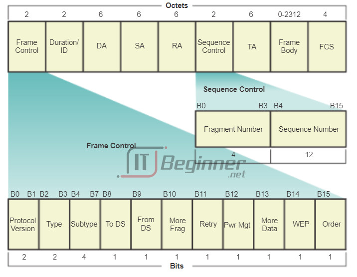
4.4.4.9 Activity – Frame Fields
4.5 Summary
4.5.1 Summary
4.5.1.1 Class Activity – Linked In!
Note: This activity is best completed in groups of 2-3 students.
Your small business is moving to a new location! Your building is brand new, and you have been tasked to come up with a physical model so that network port installation can begin.
Use the blueprint provided for this activity (your Instructor will provide you with a copy from the Instructor Planning Guide) – the area indicated by Number 1 is the reception area – the area numbered RR is the restroom area.
All rooms are within Category 6, UTP specifications (100 meters), so you have no worries about hard-wiring the building to code. Each room in the diagram must have at least one network connection available for users/intermediary devices.
With your teammate(s), indicate on the drawing:
The location of your network main distribution facility, while keeping security in mind.
The number of intermediary devices that you would use and where you would place them.
The type of cabling that would be used (UTP, STP, wireless, fiber optics, etc.) and where would the ports be placed.
The types of end devices that would be used (wired, wireless, laptops, desktops, tablets, etc.).
Do not go “overboard” on your design – just use the content from the chapter to be able to justify your decisions to the class.
Class Activity – Linked In! Instructions ./.
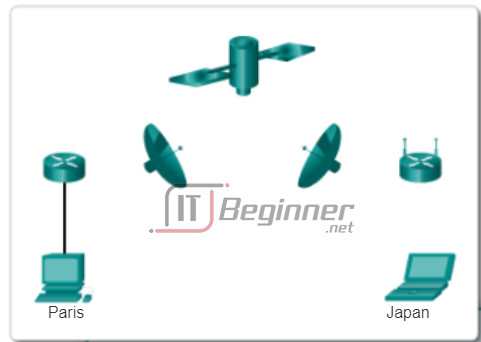
4.5.1.2 Summary
The TCP/IP network access layer is the equivalent of the OSI data link layer (Layer 2) and the physical layer (Layer 1).
The OSI physical layer provides the means to transport the bits that make up a data link layer frame across the network media. The physical components are the electronic hardware devices, media, and other connectors that transmit and carry the signals to represent the bits. Hardware components such as network adapters (NICs), interfaces and connectors, cable materials, and cable designs are all specified in standards associated with the physical layer. The physical layer standards address three functional areas: physical components, frame encoding technique, and signaling method.
Using the proper media is an important part of network communications. Without the proper physical connection, either wired or wireless, communications between any two devices will not occur.
Wired communication consists of copper media and fiber cable.
- There are three main types of copper media used in networking: unshielded-twisted pair (UTP), shielded-twisted pair (STP), and coaxial cable. UTP cabling is the most common copper networking media.
- Optical fiber cable has become very popular for interconnecting infrastructure network devices. It permits the transmission of data over longer distances and at higher bandwidths (data rates) than any other networking media. Unlike copper wires, fiber-optic cable can transmit signals with less attenuation and is completely immune to EMI and RFI.
Wireless media carry electromagnetic signals that represent the binary digits of data communications using radio or microwave frequencies.
The number of wireless enabled devices continues to increase. For these reasons, wireless has become the medium of choice for home networks and is quickly gaining in popularity in enterprise networks.
The data link layer is responsible for the exchange of frames between nodes over a physical network media. It allows the upper layers to access the media and controls how data is placed and received on the media.
Among the different implementations of the data link layer protocols, there are different methods of controlling access to the media. These media access control techniques define if and how the nodes share the media. The actual media access control method used depends on the topology and media sharing. LAN and WAN topologies can be physical or logical. It is the logical topology that influences the type of network framing and media access control used. WANs are commonly interconnected using the point-to-point, hub and spoke, or mesh physical topologies. In shared media LANs, end devices can be interconnected using the star, bus, ring, or extended star (hybrid) physical topologies.
All data link layer protocols encapsulate the Layer 3 PDU within the data field of the frame. However, the structure of the frame and the fields contained in the header and trailer vary according to the protocol.