Introduction to Networks Instructor Materials – Chapter 5: Ethernet
5.0 Ethernet
5.0.1 Introduction
5.0.1.1 Introduction
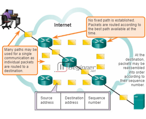
The OSI physical layer provides the means to transport the bits that make up a data link layer frame across the network media.
Ethernet is now the predominant LAN technology in the world. Ethernet operates in the data link layer and the physical layer. The Ethernet protocol standards define many aspects of network communication including frame format, frame size, timing, and encoding. When messages are sent between hosts on an Ethernet network, the hosts format the messages into the frame layout that is specified by the standards. Frames are also referred to as Protocol Data Units (PDUs).
Because Ethernet is comprised of standards at these lower layers, it may best be understood in reference to the OSI model. The OSI model separates the data link layer functionalities of addressing, framing, and accessing the media from the physical layer standards of the media. Ethernet standards define both the Layer 2 protocols and the Layer 1 technologies. Although Ethernet specifications support different media, bandwidths, and other Layer 1 and 2 variations, the basic frame format and address scheme is the same for all varieties of Ethernet.
This chapter examines the characteristics and operation of Ethernet as it has evolved from a shared media, contention-based data communications technology to today’s high bandwidth, full-duplex technology.
Upon completion of this chapter you will be able to:
- Describe the operation of the Ethernet sublayers.
- Identify the major fields of the Ethernet frame.
- Describe the purpose and characteristics of the Ethernet MAC address.
- Describe the purpose of ARP.
- Explain how ARP requests impact network and host performance.
- Explain basic switching concepts.
- Compare fixed configuration and modular switches.
- Configure a Layer 3 switch.
5.0.1.2 Activity – Join My Social Circle!
Much of our network communication takes the form of messaging (text or instant), video contact, social media postings, etc.
For this activity, choose one of the communication networks you use most:
- Text (or instant) messaging
- Audio/video conferencing
- Emailing
- Gaming
Now that you have selected a network communication type, record your answers to the following questions:
- Is there a procedure you must follow to register others and yourself so that you form a communications group?
- How do you initiate contact with the person/people with whom you wish to communicate?
- How do you limit your conversations so they are received by only those with whom you wish to communicate?
Be prepared to discuss your recorded answers in class.
Class Activity – Join My Social Circle Instructions ./.
5.1 Ethernet Protocol
5.1.1 Ethernet Operation
5.1.1.1 LLC and MAC Sublayers
Ethernet is the most widely used LAN technology used today.
Ethernet operates in the data link layer and the physical layer. It is a family of networking technologies that are defined in the IEEE 802.2 and 802.3 standards. Ethernet supports data bandwidths of:
- 10 Mb/s
- 100 Mb/s
- 1000 Mb/s (1 Gb/s)
- 10,000 Mb/s (10 Gb/s)
- 40,000 Mb/s (40 Gb/s)
- 100,000 Mb/s (100 Gb/s)
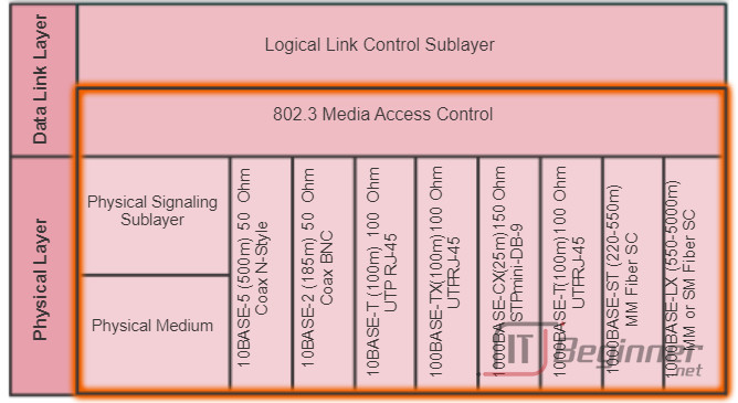
As shown in Figure 1, Ethernet standards define both the Layer 2 protocols and the Layer 1 technologies. For the Layer 2 protocols, as with all 802 IEEE standards, Ethernet relies on the two separate sublayers of the data link layer to operate, the Logical Link Control (LLC) and the MAC sublayers.
LLC sublayer
The Ethernet LLC sublayer handles the communication between the upper layers and the lower layers. This is typically between the networking software and the device hardware. The LLC sublayer takes the network protocol data, which is typically an IPv4 packet, and adds control information to help deliver the packet to the destination node. The LLC is used to communicate with the upper layers of the application, and transition the packet to the lower layers for delivery.
LLC is implemented in software, and its implementation is independent of the hardware. In a computer, the LLC can be considered the driver software for the NIC. The NIC driver is a program that interacts directly with the hardware on the NIC to pass the data between the MAC sublayer and the physical media.
MAC sublayer
MAC constitutes the lower sublayer of the data link layer. MAC is implemented by hardware, typically in the computer NIC. The specifics are specified in the IEEE 802.3 standards. Figure 2 lists common IEEE Ethernet standards.
[tabs type=”horizontal”]
[tabs_head]
[tab_title]Figure 1[/tab_title]
[tab_title]Figure 2[/tab_title]
[/tabs_head]
[tab]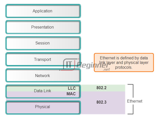 [/tab]
[tab]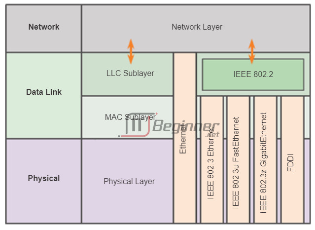 [/tab]
[/tabs]
5.1.1.2 MAC Sublayer
As shown in the figure, the Ethernet MAC sublayer has two primary responsibilities:
- Data encapsulation
- Media access control
Data encapsulation
The data encapsulation process includes frame assembly before transmission, and frame disassembly upon reception of a frame. In forming the frame, the MAC layer adds a header and trailer to the network layer PDU.
Data encapsulation provides three primary functions:
- Frame delimiting: The framing process provides important delimiters that are used to identify a group of bits that make up a frame. This process provides synchronization between the transmitting and receiving nodes.
- Addressing: The encapsulation process also provides for data link layer addressing. Each Ethernet header added in the frame contains the physical address (MAC address) that enables a frame to be delivered to a destination node.
- Error detection: Each Ethernet frame contains a trailer with a cyclic redundancy check (CRC) of the frame contents. After reception of a frame, the receiving node creates a CRC to compare to the one in the frame. If these two CRC calculations match, the frame can be trusted to have been received without error.
The use of frames aids in the transmission of bits as they are placed on the media and in the grouping of bits at the receiving node.
Media Access Control
The second responsibility of the MAC sublayer is media access control. Media access control is responsible for the placement of frames on the media and the removal of frames from the media. As its name implies, it controls access to the media. This sublayer communicates directly with the physical layer.
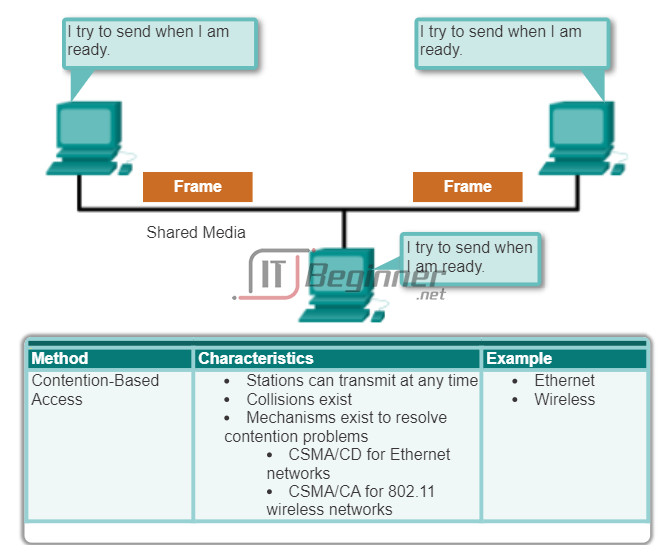
The underlying logical topology of Ethernet is a multi-access bus; therefore, all nodes (devices) on a single network segment share the medium. Ethernet is a contention-based method of networking. Recall that a contention-based method, or non-deterministic method, means that any device can try to transmit data across the shared medium whenever it has data to send. However, much like if two people try to talk simultaneously, if multiple devices on a single medium attempt to forward data simultaneously, the data will collide resulting in corrupted, unusable data. For this reason, Ethernet provides a method for controlling how the nodes share access through the use a Carrier Sense Multiple Access (CSMA) technology.
Data Encapsulation
- Frame delimiting
- Addressing
- Error detection
Media Access Control
- Control of frame placement on and off the media
- Media recovery
5.1.1.3 Media Access Control
The CSMA process is used to first detect if the media is carrying a signal. If a carrier signal on the media from another node is detected, it means that another device is transmitting. When the device attempting to transmit sees that the media is busy, it will wait and try again after a short time period. If no carrier signal is detected, the device transmits its data. It is possible that the CSMA process will fail and two devices will transmit at the same time. This is called a data collision. If this occurs, the data sent by both devices will be corrupted and will need to be resent.
Contention-based media access control methods do not require mechanisms for tracking whose turn it is to access the media; therefore, they do not have the overhead of controlled access methods. However, the contention-based systems do not scale well under heavy media use. As use and the number of nodes increases, the probability of successful media access without a collision decreases. Additionally, the recovery mechanisms required to correct errors due to these collisions further diminishes the throughput.
As shown in the figure, CSMA is usually implemented in conjunction with a method for resolving media contention. The two commonly used methods are:
CSMA/Collision Detection
In CSMA/Collision Detection (CSMA/CD), the device monitors the media for the presence of a data signal. If a data signal is absent, indicating that the media is free, the device transmits the data. If signals are then detected that show another device was transmitting at the same time, all devices stop sending and try again later. Traditional forms of Ethernet were developed to use this method.
The widespread incorporation of switched technologies in modern networks has largely displaced the original need for CSMA/CD in local-area networks. Almost all wired connections between devices in a LAN today are full-duplex connections – a device is able to send and receive simultaneously. This means, that while Ethernet networks are designed with CSMA/CD technology, with today’s intermediate devices, collisions do not occur and the processes utilized by CSMA/CD are really unnecessary.
However, wireless connections in a LAN environment still have to take collisions into account. Wireless LAN devices utilize the CSMA/Collision Avoidance (CSMA/CA) media access method.
CSMA/Collision Avoidance
In CSMA/CA, the device examines the media for the presence of a data signal. If the media is free, the device sends a notification across the media of its intent to use it. The device then sends the data. This method is used by 802.11 wireless networking technologies.
5.1.1.4 MAC Address: Ethernet Identity
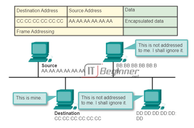
As previously stated, the underlying logical topology of Ethernet is a multi-access bus. Every network device is connected to the same, shared media, and all the nodes receive all frames transmitted. The issue is if all devices are receiving every frame, how can each individual device identify if it is the intended receiver without the overhead of having to process and de-encapsulate the frame to get to the IP address? The issue becomes even more problematic in large, high traffic volume networks where lots of frames are forwarded.
To prevent the excessive overhead involved in the processing of every frame, a unique identifier called a MAC address was created to identify the actual source and destination nodes within an Ethernet network. Regardless of which variety of Ethernet is used, MAC addressing provided a method for device identification at the lower level of the OSI model. As you may recall, MAC addressing is added as part of a Layer 2 PDU. An Ethernet MAC address is a 48-bit binary value expressed as 12 hexadecimal digits (4 bits per hexadecimal digit).
MAC Address Structure
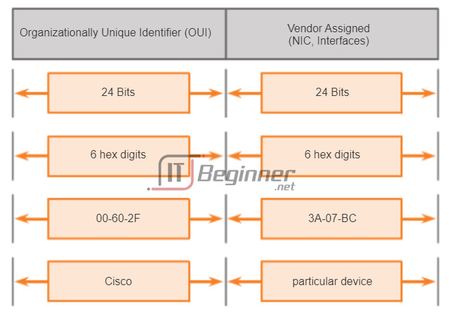
MAC addresses must be globally unique. The MAC address value is a direct result of IEEE-enforced rules for vendors to ensure globally unique addresses for each Ethernet device. The rules established by IEEE require any vendor that sells Ethernet devices to register with IEEE. The IEEE assigns the vendor a 3-byte (24-bit) code, called the Organizationally Unique Identifier (OUI).
IEEE requires a vendor to follow two simple rules, as shown in the figure:
- All MAC addresses assigned to a NIC or other Ethernet device must use that vendor’s assigned OUI as the first 3 bytes.
All MAC addresses with the same OUI must be assigned a unique value (vendor code or serial number) in the last 3 bytes.
5.1.1.5 Frame Processing
The MAC address is often referred to as a burned-in address (BIA) because, historically, this address is burned into ROM (Read-Only Memory) on the NIC. This means that the address is encoded into the ROM chip permanently – it cannot be changed by software.
Note: On modern PC operating systems and NICs, it is possible to change the MAC address in software. This is useful when attempting to gain access to a network that filters based on BIA – consequently, filtering, or controlling, traffic based on the MAC address is no longer as secure.
MAC addresses are assigned to workstations, servers, printers, switches, and routers – any device that must originate and/or receive data on the network. All devices connected to an Ethernet LAN have MAC-addressed interfaces. Different hardware and software manufacturers might represent the MAC address in different hexadecimal formats. The address formats might be similar to:
- 00-05-9A-3C-78-00
- 00:05:9A:3C:78:00
- 0005.9A3C.7800
When the computer starts up, the first thing the NIC does is copies the MAC address from ROM into RAM. When a device is forwarding a message to an Ethernet network, it attaches header information to the packet. The header information contains the source and destination MAC address. The source device sends the data through the network.
Each NIC in the network views the information, at the MAC sublayer, to see if the destination MAC address in the frame matches the device’s physical MAC address stored in RAM. If there is no match, the device discards the frame. When the frame reaches the destination where the MAC of the NIC matches the destination MAC of the frame, the NIC passes the frame up the OSI layers, where the de-encapsulation process takes place.
5.1.1.6 Activity – MAC and LLC Sublayers
5.1.2 Ethernet Frame Attributes
5.1.2.1 Ethernet Encapsulation
Since the creation of Ethernet in 1973, standards have evolved for specifying faster and more flexible versions of the technology. This ability for Ethernet to improve over time is one of the main reasons that it has become so popular. Early versions of Ethernet were relatively slow at 10 Mbps. The latest versions of Ethernet operate at 10 Gigabits per second and faster. Figure 1 highlights changes in the various versions of Ethernet.
At the data link layer, the frame structure is nearly identical for all speeds of Ethernet. The Ethernet frame structure adds headers and trailers around the Layer 3 PDU to encapsulate the message being sent.
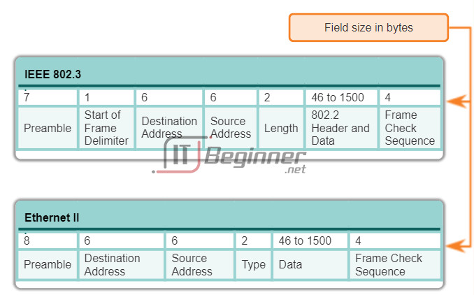
Both the Ethernet header and trailer have several sections of information that are used by the Ethernet protocol. Each section of the frame is called a field. As shown in Figure 2, there are two styles of Ethernet framing:
- IEEE 802.3 Ethernet standard which has been updated several times to include new technologies
- The DIX Ethernet standard which is now referred to Ethernet II
The differences between framing styles are minimal. The most significant difference between the two standards is the addition of a Start Frame Delimiter (SFD) and the change of the Type field to a Length field in the 802.3.
Ethernet II is the Ethernet frame format used in TCP/IP networks.
[tabs type=”horizontal”]
[tabs_head]
[tab_title]Figure 1[/tab_title]
[tab_title]Figure 2[/tab_title]
[/tabs_head]
[tab] [/tab]
[tab]
[/tab]
[/tabs]
5.1.2.2 Ethernet Frame Size
Both the Ethernet II and IEEE 802.3 standards define the minimum frame size as 64 bytes and the maximum as 1518 bytes. This includes all bytes from the Destination MAC Address field through the Frame Check Sequence (FCS) field. The Preamble and Start Frame Delimiter fields are not included when describing the size of a frame.
Any frame less than 64 bytes in length is considered a “collision fragment” or “runt frame” and is automatically discarded by receiving stations.
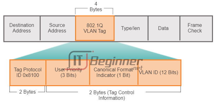
The IEEE 802.3ac standard, released in 1998, extended the maximum allowable frame size to 1522 bytes. The frame size was increased to accommodate a technology called Virtual Local Area Network (VLAN). VLANs are created within a switched network and will be presented in a later course. Also, many quality of service (QoS) technologies leverage the User Priority field to implement various levels of service, such as priority service for voice traffic. The figure displays the fields contained in the 802.1Q VLAN tag.
If the size of a transmitted frame is less than the minimum or greater than the maximum, the receiving device drops the frame. Dropped frames are likely to be the result of collisions or other unwanted signals and are therefore considered invalid.
At the data link layer the frame structure is nearly identical. At the physical layer different versions of Ethernet vary in their method for detecting and placing data on the media.
5.1.2.3 Introduction to the Ethernet Frame
The primary fields in the Ethernet frame are:
- Preamble and Start Frame Delimiter Fields: The Preamble (7 bytes) and Start Frame Delimiter (SFD), also called the Start of Frame (1 byte), fields are used for synchronization between the sending and receiving devices. These first eight bytes of the frame are used to get the attention of the receiving nodes. Essentially, the first few bytes tell the receivers to get ready to receive a new frame.
- Destination MAC Address Field: This 6-byte field is the identifier for the intended recipient. As you will recall, this address is used by Layer 2 to assist devices in determining if a frame is addressed to them. The address in the frame is compared to the MAC address in the device. If there is a match, the device accepts the frame.
- Source MAC Address Field: This 6-byte field identifies the frame’s originating NIC or interface.
- Length Field: For any IEEE 802.3 standard earlier than 1997 the Length field defines the exact length of the frame’s data field. This is used later as part of the FCS to ensure that the message was received properly. Otherwise the purpose of the field is to describe which higher-layer protocol is present. If the two-octet value is equal to or greater than 0x0600 hexadecimal or 1536 decimal, then the contents of the Data field are decoded according to the EtherType protocol indicated. Whereas if the value is equal to or less than 0x05DC hexadecimal or 1500 decimal then the Length field is being used to indicate the use of the IEEE 802.3 frame format. This is how Ethernet II and 802.3 frames are differentiated.
- Data Field: This field (46 – 1500 bytes) contains the encapsulated data from a higher layer, which is a generic Layer 3 PDU, or more commonly, an IPv4 packet. All frames must be at least 64 bytes long. If a small packet is encapsulated, additional bits called a pad are used to increase the size of the frame to this minimum size.
- Frame Check Sequence Field: The Frame Check Sequence (FCS) field (4 bytes) is used to detect errors in a frame. It uses a cyclic redundancy check (CRC). The sending device includes the results of a CRC in the FCS field of the frame. The receiving device receives the frame and generates a CRC to look for errors. If the calculations match, no error occurred. Calculations that do not match are an indication that the data has changed; therefore, the frame is dropped. A change in the data could be the result of a disruption of the electrical signals that represent the bits.
5.1.2.4 Activity – Ethernet Frame Fields
5.1.3 Ethernet MAC
5.1.3.1 MAC Addresses and Hexadecimal
The use of the MAC address is one of the most important aspects of the Ethernet LAN technology. MAC addresses use hexadecimal numbering.
Hexadecimal is a word that is used both as a noun and as an adjective. When used by itself (as a noun) it means the hexadecimal number system. Hexadecimal provides a convenient way to represent binary values. Just as decimal is a base ten number system and binary is a base two number system, hexadecimal is a base sixteen system.
The base sixteen number system uses the numbers 0 to 9 and the letters A to F. Figure 1 shows the equivalent decimal and hexadecimal values for binary 0000 to 1111. It is easier for us to express a value as a single hexadecimal digit than as four binary bits.
Given that 8 bits (a byte) is a common binary grouping, binary 00000000 to 11111111 can be represented in hexadecimal as the range 00 to FF. Leading zeroes are always displayed to complete the 8-bit representation. For example, the binary value 0000 1010 is shown in hexadecimal as 0A.
Note: It is important to distinguish hexadecimal values from decimal values regarding the characters 0 to 9, as shown in Figure 1.
Representing Hexadecimal Values
Hexadecimal is usually represented in text by the value preceded by 0x (for example 0x73) or a subscript 16. Less commonly, it may be followed by an H, for example 73H. However, because subscript text is not recognized in command line or programming environments, the technical representation of hexadecimal is preceded with “0x” (zero X). Therefore, the examples above would be shown as 0x0A and 0x73 respectively.
Hexadecimal is used to represent Ethernet MAC addresses and IP Version 6 addresses.
Hexadecimal Conversions
Number conversions between decimal and hexadecimal values are straightforward, but quickly dividing or multiplying by 16 is not always convenient. If such conversions are required, it is usually easier to convert the decimal or hexadecimal value to binary, and then to convert the binary value to either decimal or hexadecimal as appropriate.
With practice, it is possible to recognize the binary bit patterns that match the decimal and hexadecimal values. Figure 2 shows these patterns for selected 8-bit values.
[tabs type=”horizontal”]
[tabs_head]
[tab_title]Figure 1[/tab_title]
[tab_title]Figure 2[/tab_title]
[/tabs_head]
[tab]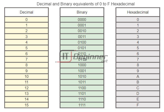 [/tab]
[tab]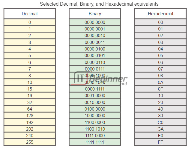 [/tab]
[/tabs]
5.1.3.2 MAC Address Representations
On a Windows host, the ipconfig /all command can be used to identify the MAC address of an Ethernet adapter. In Figure 1, notice the display indicates the Physical Address (MAC) of the computer to be 00-18-DE-C7-F3-FB. If you have access, you may wish to try this on your own computer.
Depending on the device and the operating system, you will see various representations of MAC addresses, as displayed in Figure 2. Cisco routers and switches use the form XXXX.XXXX.XXXX where X is a hexadecimal character.
[tabs type=”horizontal”]
[tabs_head]
[tab_title]Physical Address of a Host[/tab_title]
[tab_title]Different Representations of MAC Addresses[/tab_title]
[/tabs_head]
[tab]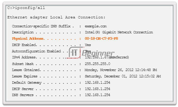 [/tab]
[tab]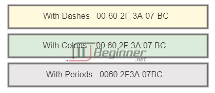 [/tab]
[/tabs]
5.1.3.3 Unicast MAC Address
In Ethernet, different MAC addresses are used for Layer 2 unicast, broadcast, and multicast communications.
A unicast MAC address is the unique address used when a frame is sent from a single transmitting device to a single destination device.
In the example shown in the figure, a host with IP address 192.168.1.5 (source) requests a web page from the server at IP address 192.168.1.200. For a unicast packet to be sent and received, a destination IP address must be in the IP packet header. A corresponding destination MAC address must also be present in the Ethernet frame header. The IP address and MAC address combine to deliver data to one specific destination host.
5.1.3.4 Broadcast MAC Address
A broadcast packet contains a destination IP address that has all ones (1s) in the host portion. This numbering in the address means that all hosts on that local network (broadcast domain) will receive and process the packet. Many network protocols, such as DHCP and Address Resolution Protocol (ARP), use broadcasts. How ARP uses broadcasts to map Layer 2 to Layer 3 addresses is discussed later in this chapter.
As shown in the figure, a broadcast IP address for a network needs a corresponding broadcast MAC address in the Ethernet frame. On Ethernet networks, the broadcast MAC address is 48 ones displayed as hexadecimal FF-FF-FF-FF-FF-FF.
5.1.3.5 Multicast MAC Address
Multicast addresses allow a source device to send a packet to a group of devices. Devices that belong to a multicast group are assigned a multicast group IP address. The range of IPv4 multicast addresses is 224.0.0.0 to 239.255.255.255. Because multicast addresses represent a group of addresses (sometimes called a host group), they can only be used as the destination of a packet. The source will always have a unicast address.
Multicast addresses would be used in remote gaming, where many players are connected remotely but playing the same game. Another use of multicast addresses is in distance learning through video conferencing, where many students are connected to the same class.
As with the unicast and broadcast addresses, the multicast IP address requires a corresponding multicast MAC address to actually deliver frames on a local network. The multicast MAC address is a special value that begins with 01-00-5E in hexadecimal. The remaining portion of the multicast MAC address is created by converting the lower 23 bits of the IP multicast group address into 6 hexadecimal characters.
An example, as shown in the animation, is the multicast hexadecimal address 01-00-5E-00-00-C8.
5.1.3.6 Lab – Viewing Network Device MAC Addresses
In this lab, you will complete the following objectives:
- Part 1: Set Up the Topology and Initialize Devices
- Part 2: Configure Devices and Verify Connectivity
- Part 3: Display, Describe, and Analyze Ethernet MAC Addresses
Lab – Viewing Network Device MAC Addresses ./.
5.1.4 MAC and IP
5.1.4.1 MAC and IP
There are two primary addresses assigned to a host device:
- Physical address (the MAC address)
- Logical address (the IP address)
Both the MAC address and IP address work together to identify a device on the network. The process of using the MAC address and the IP address to find a computer is similar to the process of using a name and address of an individual to send a letter.
A person’s name usually does not change. A person’s address on the other hand, relates to where they live and can change.
Similar to the name of a person, the MAC address on a host does not change; it is physically assigned to the host NIC and is known as the physical address. The physical address remains the same regardless of where the host is placed.
The IP address is similar to the address of a person. This address is based on where the host is actually located. Using this address, it is possible for a frame to determine the location of where a frame should be sent. The IP address, or network address, is known as a logical address because it is assigned logically. It is assigned to each host by a network administrator based on the local network that the host is connected to. The figure demonstrates the hierarchical nature of locating an individual based on a “logical” address. Click each grouping to view how the address filters down.
Both the physical MAC and logical IP addresses are required for a computer to communicate on a hierarchical network, just like both the name and address of a person are required to send a letter.
5.1.4.2 End-to-End Connectivity, MAC, and IP
A source device will send a packet based on an IP address. One of the most common ways a source device determines the IP address of a destination device is through Domain Name Service (DNS), in which an IP address is associated to a domain name. For example, www.cisco.com is equal to 209.165.200.225. This IP address will get the packet to the network location of the destination device. It is this IP address that routers will use to determine the best path to reach a destination. So, in short, IP addressing determines the end-to-end behavior of an IP packet.
However, along each link in a path, an IP packet is encapsulated in a frame specific to the particular data link technology associated with that link, such as Ethernet. End devices on an Ethernet network do not accept and process frames based on IP addresses, rather, a frame is accepted and processed based on MAC addresses.
On Ethernet networks, MAC addresses are used to identify, at a lower level, the source and destination hosts. When a host on an Ethernet network communicates, it sends frames containing its own MAC address as the source and the MAC address of the intended recipient as the destination. All hosts that receive the frame will read the destination MAC address. If the destination MAC address matches the MAC address configured on the host NIC, only then will the host process the message.
Figure 1 shows how a data packet, containing IP address information, is encapsulated with data link layer framing containing the MAC address information.
Figure 2 shows how frames are encapsulated based on the technology of the actual link.
How are the IP addresses of the IP packets in a data flow associated with the MAC addresses on each link along the path to the destination? This is done through a process called Address Resolution Protocol (ARP).
[tabs type=”horizontal”]
[tabs_head]
[tab_title]IP Packet Encapsulated in an Ethernet Frame[/tab_title]
[tab_title]The Data Link Layer[/tab_title]
[/tabs_head]
[tab] [/tab]
[tab] [/tab]
[/tabs]
5.1.4.3 Lab – Using Wireshark to Examine Ethernet Frames
In this lab, you will complete the following objectives:
- Part 1: Examine the Header Fields in an Ethernet II Frame
- Part 2: Use Wireshark to Capture and Analyze Ethernet Frames
Lab – Using Wireshark to Examine Ethernet Frames ./.
5.1.4.4 Packet Tracer – Identify MAC and IP Addresses
This activity is optimized for viewing PDUs. The devices are already configured. You will gather PDU information in simulation mode and answer a series of questions about the data you collect.
Packet Tracer – Identify MAC and IP Addresses Instructions ./.
Packet Tracer – Identify MAC and IP Addresses – PKA ./.
5.2 Address Resolution Protocol
5.2.1 ARP
5.2.1.1 Introduction to ARP
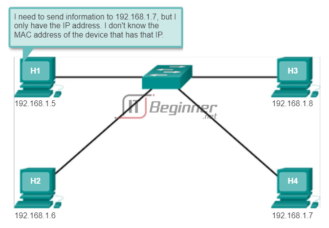
Recall that each node on an IP network has both a MAC address and an IP address. In order to send data, the node must use both of these addresses. The node must use its own MAC and IP addresses in the source fields and must provide both a MAC address and an IP address for the destination. While the IP address of the destination will be provided by a higher OSI layer, the sending node needs a way to find the MAC address of the destination for a given Ethernet link. This is the purpose of ARP.
ARP relies on certain types of Ethernet broadcast messages and Ethernet unicast messages, called ARP requests and ARP replies.
The ARP protocol provides two basic functions:
- Resolving IPv4 addresses to MAC addresses
- Maintaining a table of mappings
5.2.1.2 ARP Functions
Resolving IPv4 Addresses to MAC Addresses
For a frame to be placed on the LAN media, it must have a destination MAC address. When a packet is sent to the data link layer to be encapsulated into a frame, the node refers to a table in its memory to find the data link layer address that is mapped to the destination IPv4 address. This table is called the ARP table or the ARP cache. The ARP table is stored in the RAM of the device.
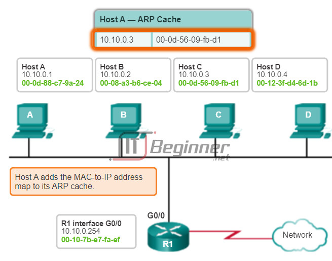
Each entry, or row, of the ARP table binds an IP address with a MAC address. We call the relationship between the two values a map – it simply means that you can locate an IP address in the table and discover the corresponding MAC address. The ARP table temporarily saves (caches) the mapping for the devices on the local LAN.
To begin the process, a transmitting node attempts to locate the MAC address mapped to an IPv4 destination. If this map is found in the table, the node uses the MAC address as the destination MAC in the frame that encapsulates the IPv4 packet. The frame is then encoded onto the networking media.
Maintaining the ARP Table
The ARP table is maintained dynamically. There are two ways that a device can gather MAC addresses. One way is to monitor the traffic that occurs on the local network segment. As a node receives frames from the media, it can record the source IP and MAC address as a mapping in the ARP table. As frames are transmitted on the network, the device populates the ARP table with address pairs.
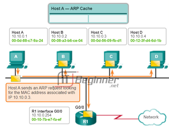
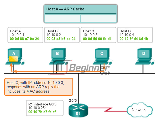
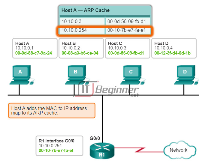
Another way a device can get an address pair is to send an ARP request as shown in the figure. An ARP request is a Layer 2 broadcast to all devices on the Ethernet LAN. The ARP request contains the IP address of the destination host and the broadcast MAC address, FFFF.FFFF.FFFF. Since this is a broadcast, all nodes on the Ethernet LAN will receive it and look at the contents. The node with the IP address that matches the IP address in the ARP request will reply. The reply will be a unicast frame that includes the MAC address that corresponds to the IP address in the request. This response is then used to make a new entry in the ARP table of the sending node.
Entries in the ARP table are time stamped in much the same way that MAC table entries are time stamped in switches. If a device does not receive a frame from a particular device by the time the time stamp expires, the entry for this device is removed from the ARP table.
Additionally, static map entries can be entered in an ARP table, but this is rarely done. Static ARP table entries do not expire over time and must be manually removed.
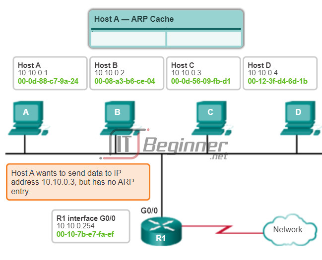
5.2.1.3 ARP Operation
Creating the Frame
What does a node do when it needs to create a frame and the ARP cache does not contain a map of an IP address to a destination MAC address? It generates an ARP request!
When ARP receives a request to map an IPv4 address to a MAC address, it looks for the cached map in its ARP table. If an entry is not found, the encapsulation of the IPv4 packet fails and the Layer 2 processes notify ARP that it needs a map. The ARP processes then send out an ARP request packet to discover the MAC address of the destination device on the local network. If a device receiving the request has the destination IP address, it responds with an ARP reply. A map is created in the ARP table. Packets for that IPv4 address can now be encapsulated in frames.
If no device responds to the ARP request, the packet is dropped because a frame cannot be created. This encapsulation failure is reported to the upper layers of the device. If the device is an intermediary device, like a router, the upper layers may choose to respond to the source host with an error in an ICMPv4 packet.
See Figures 1-5 to view the process used to get the MAC address of the node on the local physical network.
[tabs type=”horizontal”]
[tabs_head]
[tab_title]Figures 1[/tab_title]
[tab_title]Figures 2[/tab_title]
[tab_title]Figures 3[/tab_title]
[tab_title]Figures 4[/tab_title]
[tab_title]Figures 5[/tab_title]
[/tabs_head]
[tab]
[/tab]
[tab]
[/tab]
[tab]
[/tab]
[tab]
[/tab]
[tab]
[/tab]
[/tabs]
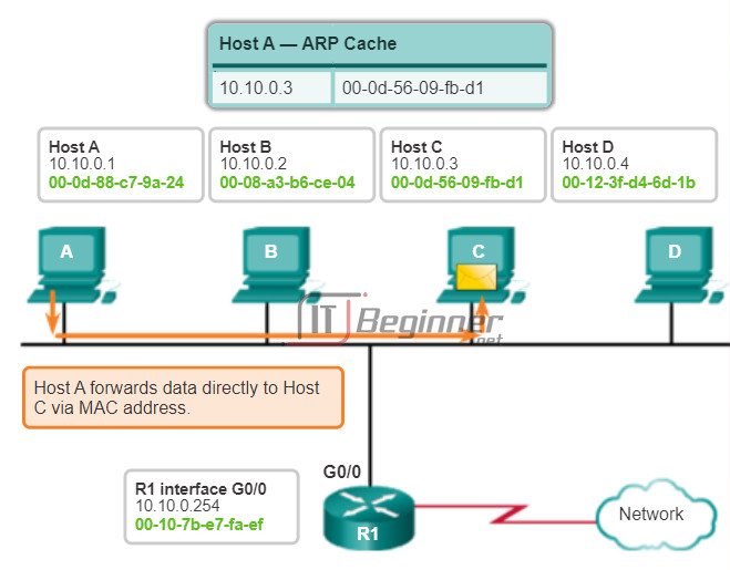
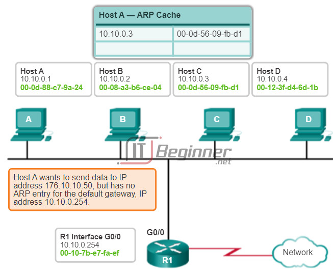
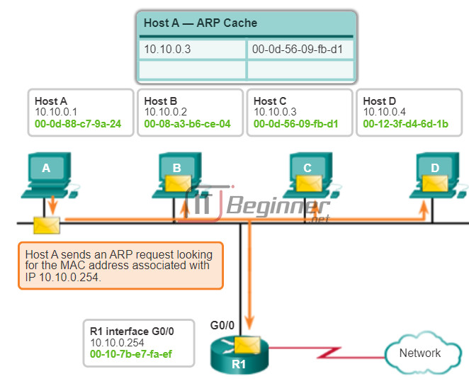
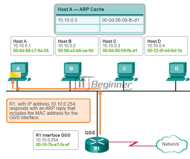
5.2.1.4 ARP Role in Remote Communication
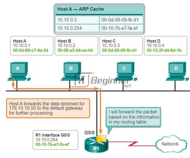
All frames must be delivered to a node on the local network segment. If the destination IPv4 host is on the local network, the frame will use the MAC address of this device as the destination MAC address.
If the destination IPv4 host is not on the local network, the source node needs to deliver the frame to the router interface that is the gateway or next hop used to reach that destination. The source node will use the MAC address of the gateway as the destination address for frames containing an IPv4 packet addressed to hosts on other networks.
The gateway address of the router interface is stored in the IPv4 configuration of the hosts. When a host creates a packet for a destination, it compares the destination IP address and its own IP address to determine if the two IP addresses are located on the same Layer 3 network. If the receiving host is not on the same network, the source uses the ARP process to determine a MAC address for the router interface serving as the gateway.
In the event that the gateway entry is not in the table, the normal ARP process will send an ARP request to retrieve the MAC address associated with the IP address of the router interface.
See Figures 1-5 to view the process used to get the MAC address of the gateway.
[tabs type=”horizontal”]
[tabs_head]
[tab_title]Figures 1[/tab_title]
[tab_title]Figures 2[/tab_title]
[tab_title]Figures 3[/tab_title]
[tab_title]Figures 4[/tab_title]
[tab_title]Figures 5[/tab_title]
[/tabs_head]
[tab]
[/tab]
[tab]
[/tab]
[tab]
[/tab]
[tab]
[/tab]
[tab]
[/tab]
[/tabs]
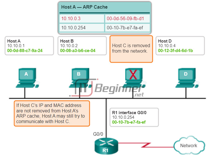
5.2.1.5 Removing Entries from an ARP Table
For each device, an ARP cache timer removes ARP entries that have not been used for a specified period of time. The times differ depending on the device and its operating system. For example, some Windows operating systems store ARP cache entries for 2 minutes. If the entry is used again during that time, the ARP timer for that entry is extended to 10 minutes.
Commands may also be used to manually remove all or some of the entries in the ARP table. After an entry has been removed, the process for sending an ARP request and receiving an ARP reply must occur again to enter the map in the ARP table.
Each device has an operating system-specific command to delete the contents of the ARP cache. These commands do not invoke the execution of ARP in any way. They merely remove the entries of the ARP table. ARP service is integrated within the IPv4 protocol and implemented by the device. Its operation is transparent to both upper layer applications and users.
As shown in the figure, it is sometimes necessary to remove an ARP table entry.
5.2.1.6 ARP Tables on Networking Devices
On a Cisco router, the show ip arp command is used to display the ARP table, as shown in Figure 1.
On a Windows 7 PC, the arp –a command is used to display the ARP table, as shown in Figure 2.
[tabs type=”horizontal”]
[tabs_head]
[tab_title]Router ARP Table[/tab_title]
[tab_title]Host ARP Table[/tab_title]
[/tabs_head]
[tab]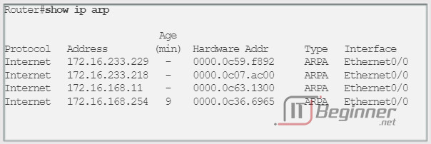 [/tab]
[tab]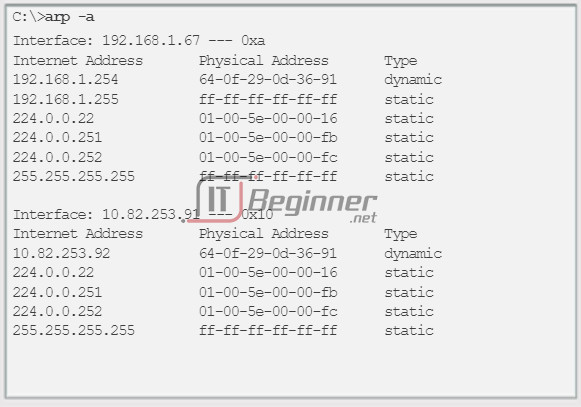 [/tab]
[/tabs]
5.2.1.7 Packet Tracer – Examine the ARP Table
This activity is optimized for viewing PDUs. The devices are already configured. You will gather PDU information in simulation mode and answer a series of questions about the data you collect.
Packet Tracer – Examine the ARP Table Instructions ./.
Packet Tracer – Examine the ARP Table – PKA ./.
5.2.1.8 Lab – Observing ARP with the Windows CLI, IOS CLI, and Wireshark
In this lab, you will complete the following objectives:
- Part 1: Build and Configure the Network
- Part 2: Use the Windows ARP Command
- Part 3: Use the IOS Show ARP Command
- Part 4: Use Wireshark to Examine ARP Exchanges
Lab – Observing ARP with the Windows CLI, IOS CLI, and Wireshark ./.
5.2.2 ARP Issues
5.2.2.1 How ARP Can Create Problems
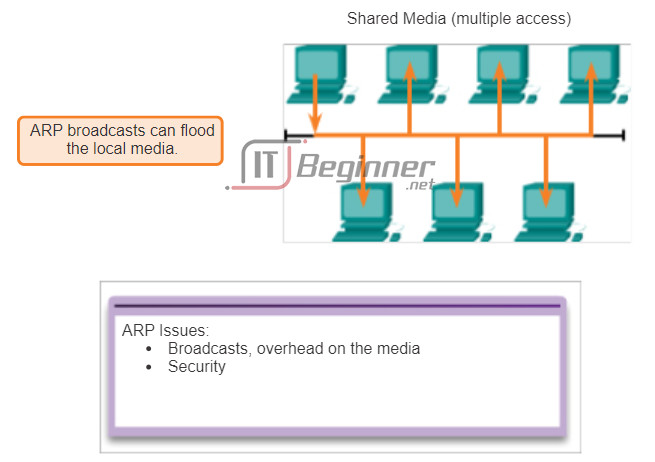
The figure shows two potential issues with ARP.
Overhead on the Media
As a broadcast frame, an ARP request is received and processed by every device on the local network. On a typical business network, these broadcasts would probably have minimal impact on network performance. However, if a large number of devices were to be powered up and all start accessing network services at the same time, there could be some reduction in performance for a short period of time. For example, if all students in a lab logged into classroom computers and attempted to access the Internet at the same time, there could be delays. However, after the devices send out the initial ARP broadcasts and have learned the necessary MAC addresses, any impact on the network will be minimized.
Security
In some cases, the use of ARP can lead to a potential security risk. ARP spoofing, or ARP poisoning, is a technique used by an attacker to inject the wrong MAC address association into a network by issuing fake ARP requests. An attacker forges the MAC address of a device and then frames can be sent to the wrong destination.
Manually configuring static ARP associations is one way to prevent ARP spoofing. Authorized MAC addresses can be configured on some network devices to restrict network access to only those devices listed.
5.2.2.2 Mitigating ARP Problems
Broadcast and security issues related to ARP can be mitigated with modern switches. Cisco switches support several security technologies specifically designed to mitigate Ethernet issues related to broadcasts, in general, and ARP, in particular.
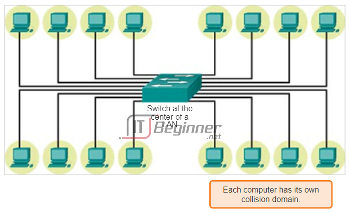
Switches provide segmentation of a LAN, dividing the LAN into independent collision domains. Each port on a switch represents a separate collision domain and provides the full media bandwidth to the node or nodes connected on that port. While switches do not by default prevent broadcasts from propagating to connected devices, they do isolate unicast Ethernet communications so that they are only “heard” by the source and destination devices. So if there are a large number of ARP requests, each ARP reply will only be between two devices.
With regard to mitigating various types of broadcast attacks, to which Ethernet networks are prone, network engineers implement Cisco switch security technologies such as specialized access lists and port security.
5.3 LAN Switches
5.3.1 Switching
5.3.1.1 Switch Port Fundamentals
Recall that the logical topology of an Ethernet network is a multi-access bus in which devices all share access to the same medium. This logical topology determines how hosts on the network view and process frames sent and received on the network. However, the physical topology of most Ethernet networks today is that of a star or extended star. This means that on most Ethernet networks, end devices are typically connected, in a point-to-point basis, to a Layer 2 LAN switch.
A Layer 2 LAN switch performs switching and filtering based only on the OSI data link layer (Layer 2) MAC address. A switch is completely transparent to network protocols and user applications. A Layer 2 switch builds a MAC address table that it uses to make forwarding decisions. Layer 2 switches depend on routers to pass data between independent IP subnetworks.
5.3.1.2 Switch MAC Address Table
Switches use MAC addresses to direct network communications through their switch fabric to the appropriate port toward the destination node. The switch fabric is the integrated circuits and the accompanying machine programming that allows the data paths through the switch to be controlled. For a switch to know which port to use to transmit a unicast frame, it must first learn which nodes exist on each of its ports.
A switch determines how to handle incoming data frames by using its MAC address table. A switch builds its MAC address table by recording the MAC addresses of the nodes connected to each of its ports. Once a MAC address for a specific node on a specific port is recorded in the address table, the switch then knows to send traffic destined for that specific node out the port mapped to that node for subsequent transmissions.
When an incoming data frame is received by a switch and the destination MAC address is not in the table, the switch forwards the frame out all ports, except for the port on which it was received. When the destination node responds, the switch records the node’s MAC address in the address table from the frame’s source address field. In networks with multiple interconnected switches, the MAC address tables record multiple MAC addresses for the ports connecting the switches which reflect the node’s beyond. Typically, switch ports used to interconnect two switches have multiple MAC addresses recorded in the MAC address table.
To see how this works, view each of the steps in Figures 1-6.
The following describes this process:
Step 1. The switch receives a broadcast frame from PC1 on Port 1.
Step 2. The switch enters the source MAC address and the switch port that received the frame into the address table.
Step 3. Because the destination address is a broadcast, the switch floods the frame to all ports, except the port on which it received the frame.
Step 4. The destination device replies to the broadcast with a unicast frame addressed to PC1.
Step 5. The switch enters the source MAC address of PC2 and the port number of the switch port that received the frame into the address table. The destination address of the frame and its associated port is found in the MAC address table.
Step 6. The switch can now forward frames between source and destination devices without flooding, because it has entries in the address table that identify the associated ports.
Note: The MAC address table is sometimes referred to as a content addressable memory (CAM) table. While the term CAM table is fairly common, for the purposes of this course, we will refer to it as a MAC address table.
[tabs type=”horizontal”]
[tabs_head]
[tab_title]Step 1[/tab_title]
[tab_title]Step 2[/tab_title]
[tab_title]Step 3[/tab_title]
[tab_title]Step 4[/tab_title]
[tab_title]Step 5[/tab_title]
[tab_title]Step 6[/tab_title]
[/tabs_head]
[tab]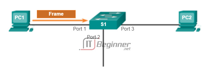 [/tab]
[tab]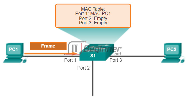 [/tab]
[tab]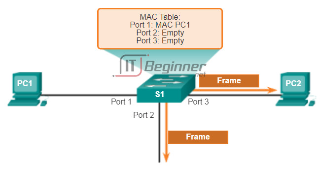 [/tab]
[tab]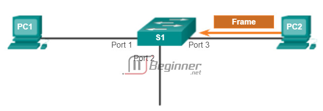 [/tab]
[tab]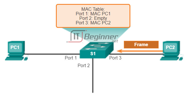 [/tab]
[tab]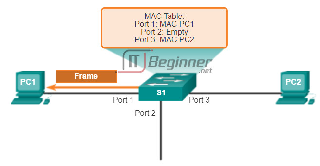 [/tab]
[/tabs]
5.3.1.3 Duplex Settings
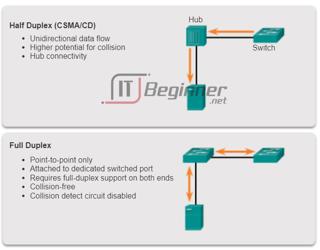
Though transparent to network protocols and user applications, switches can operate in different modes that can have both positive and negative effects when forwarding Ethernet frames on a network. One of the most basic settings of a switch is the duplex setting of each individual port connected to each host device. A port on a switch must be configured to match the duplex settings of the media type. There are two types of duplex settings used for communications on an Ethernet network: half duplex and full duplex.
Half Duplex
Half-duplex communication relies on unidirectional data flow where sending and receiving data are not performed at the same time. This is similar to how walkie-talkies or two-way radios function in that only one person can talk at any one time. If someone talks while someone else is already speaking, a collision occurs. As a result, half-duplex communication implements CSMA/CD to help reduce the potential for collisions and detect them when they do happen. Half-duplex communications have performance issues due to the constant waiting, because data can only flow in one direction at a time. Half-duplex connections are typically seen in older hardware, such as hubs. Nodes that are attached to hubs that share their connection to a switch port must operate in half-duplex mode because the end computers must be able to detect collisions. Nodes can operate in a half-duplex mode if the NIC card cannot be configured for full duplex operations. In this case the port on the switch defaults to a half-duplex mode as well. Because of these limitations, full-duplex communication has replaced half duplex in more current hardware.
Full Duplex
In full-duplex communication, data flow is bidirectional, so data can be sent and received at the same time. The bidirectional support enhances performance by reducing the wait time between transmissions. Most Ethernet, Fast Ethernet, and Gigabit Ethernet NICs sold today offer full-duplex capability. In full-duplex mode, the collision detect circuit is disabled. Frames sent by the two connected end nodes cannot collide because the end nodes use two separate circuits in the network cable. Each full-duplex connection uses only one port. Full-duplex connections require a switch that supports full duplex or a direct connection between two nodes that each support full duplex. Nodes that are directly attached to a dedicated switch port with NICs that support full duplex should be connected to switch ports that are configured to operate in full-duplex mode.
The figure shows the two duplex settings available on modern network equipment.
A Cisco Catalyst switch supports three duplex settings:
- The full option sets full-duplex mode.
- The half option sets half-duplex mode.
- The auto option sets autonegotiation of duplex mode. With autonegotiation enabled, the two ports communicate to decide the best mode of operation.
For Fast Ethernet and 10/100/1000 ports, the default is auto. For 100BASE-FX ports, the default is full. The 10/100/1000 ports operate in either half- or full-duplex mode when they are set to 10 or 100 Mb/s, but when set to 1,000 Mb/s, they operate only in full-duplex mode.
5.3.1.4 Auto-MDIX
In addition to having the correct duplex setting, it is also necessary to have the correct cable type defined for each port. Connections between specific devices, such as switch-to-switch, switch-to-router, switch-to-host, and router-to-host device, once required the use of a specific cable types (crossover or straight-through). Instead, most switch devices now support the mdix auto interface configuration command in the CLI to enable the automatic medium-dependent interface crossover (auto-MDIX) feature.
When the auto-MDIX feature is enabled, the switch detects the required cable type for copper Ethernet connections and configures the interfaces accordingly. Therefore, you can use either a crossover or a straight-through cable for connections to a copper 10/100/1000 port on the switch, regardless of the type of device on the other end of the connection.
The auto-MDIX feature is enabled by default on switches running Cisco IOS Release 12.2(18)SE or later. For releases between Cisco IOS Release 12.1(14)EA1 and 12.2(18)SE, the auto-MDIX feature is disabled by default.
5.3.1.5 Frame Forwarding Methods on Cisco Switches
In the past, switches used one of the following forwarding methods for switching data between network ports:
- Store-and-forward switching
- Cut-through switching
Figure 1 highlights differences between these two methods.
In store-and-forward switching, when the switch receives the frame, it stores the data in buffers until the complete frame has been received. During the storage process, the switch analyzes the frame for information about its destination. In this process, the switch also performs an error check using the Cyclic Redundancy Check (CRC) trailer portion of the Ethernet frame.
CRC uses a mathematical formula, based on the number of bits (1s) in the frame, to determine whether the received frame has an error. After confirming the integrity of the frame, the frame is forwarded out the appropriate port toward its destination. When an error is detected in a frame, the switch discards the frame. Discarding frames with errors reduces the amount of bandwidth consumed by corrupt data. Store-and-forward switching is required for Quality of Service (QoS) analysis on converged networks where frame classification for traffic prioritization is necessary. For example, voice over IP data streams need to have priority over web-browsing traffic.
In Figure 2, play the animation for a demonstration of the store-and-forward process. Store-and-forward is the sole forwarding method used on current models of Cisco Catalyst switches.
[tabs type=”horizontal”]
[tabs_head]
[tab_title]Switch Packet Forwarding Methods[/tab_title]
[tab_title]Store-and-Forward Switching[/tab_title]
[/tabs_head]
[tab]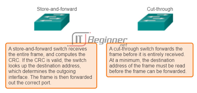 [/tab]
[tab] [/tab]
[/tabs]
5.3.1.6 Cut-Through Switching
In cut-through switching, the switch acts upon the data as soon as it is received, even if the transmission is not complete. The switch buffers just enough of the frame to read the destination MAC address so that it can determine to which port to forward the data. The destination MAC address is located in the first 6 bytes of the frame following the preamble. The switch looks up the destination MAC address in its switching table, determines the outgoing interface port, and forwards the frame onto its destination through the designated switch port. The switch does not perform any error checking on the frame. Because the switch does not have to wait for the entire frame to be completely buffered, and because the switch does not perform any error checking, cut-through switching is faster than store-and-forward switching. However, because the switch does not perform any error checking, it forwards corrupt frames throughout the network. The corrupt frames consume bandwidth while they are being forwarded. The destination NIC eventually discards the corrupt frames.
Play the animation for a demonstration of the cut-through switching process.
There are two variants of cut-through switching:
- Fast-forward switching: Fast-forward switching offers the lowest level of latency. Fast-forward switching immediately forwards a packet after reading the destination address. Because fast-forward switching starts forwarding before the entire packet has been received, there may be times when packets are relayed with errors. This occurs infrequently, and the destination network adapter discards the faulty packet upon receipt. In fast-forward mode, latency is measured from the first bit received to the first bit transmitted. Fast-forward switching is the typical cut-through method of switching.
- Fragment-free switching: In fragment-free switching, the switch stores the first 64 bytes of the frame before forwarding. Fragment-free switching can be viewed as a compromise between store-and-forward switching and fast-forward switching. The reason fragment-free switching stores only the first 64 bytes of the frame is that most network errors and collisions occur during the first 64 bytes. Fragment-free switching tries to enhance fast-forward switching by performing a small error check on the first 64 bytes of the frame to ensure that a collision has not occurred before forwarding the frame. Fragment-free switching is a compromise between the high latency and high integrity of store-and-forward switching, and the low latency and reduced integrity of fast-forward switching.
The figure shows an example of cut-through switching.
Some switches are configured to perform cut-through switching on a per-port basis until a user-defined error threshold is reached and then they automatically change to store-and-forward. When the error rate falls below the threshold, the port automatically changes back to cut-through switching.
5.3.1.7 Activity – Frame Forwarding Methods
5.3.1.8 Memory Buffering on Switches
As discussed, a switch analyzes some or all of a packet before it forwards it to the destination host. An Ethernet switch may use a buffering technique to store frames before forwarding them. Buffering may also be used when the destination port is busy due to congestion and the switch stores the frame until it can be transmitted.
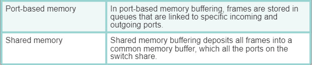
As shown in the figure, there are two methods of memory buffering: port-based and shared memory.
Port-based Memory Buffering
In port-based memory buffering, frames are stored in queues that are linked to specific incoming and outgoing ports. A frame is transmitted to the outgoing port only when all the frames ahead of it in the queue have been successfully transmitted. It is possible for a single frame to delay the transmission of all the frames in memory because of a busy destination port. This delay occurs even if the other frames could be transmitted to open destination ports.
Shared Memory Buffering
Shared memory buffering deposits all frames into a common memory buffer that all the ports on the switch share. The amount of buffer memory required by a port is dynamically allocated. The frames in the buffer are linked dynamically to the destination port. This allows the packet to be received on one port and then transmitted on another port, without moving it to a different queue.
The switch keeps a map of frame to port links showing where a packet needs to be transmitted. The map link is cleared after the frame has been successfully transmitted. The number of frames stored in the buffer is restricted by the size of the entire memory buffer and not limited to a single port buffer. This permits larger frames to be transmitted with fewer dropped frames. This is especially important to asymmetric switching. Asymmetric switching allows for different data rates on different ports. This allows more bandwidth to be dedicated to certain ports, such as a port connected to a server.
5.3.1.9 Activity – Switch It!
5.3.1.10 Lab – Viewing the Switch MAC Address Table
In this lab, you will complete the following objectives:
- Part 1: Build and Configure the Network
- Part 2: Examine the Switch MAC Address Table
Lab – Using IOS CLI with Switch MAC Address Tables ./.
5.3.2 Fixed or Modular
5.3.2.1 Fixed versus Modular Configuration
When selecting a switch, it is important to understand the key features of the switch options available. This means that it is necessary to decide on features such as whether Power over Ethernet (PoE) is necessary, and the preferred “forwarding rate”.
As shown in Figure 1, PoE allows a switch to deliver power to a device, such as IP phones and some wireless access points, over the existing Ethernet cabling. This allows more flexibility for installation.
The forwarding rate defines the processing capabilities of a switch by rating how much data the switch can process per second. Switch product lines are classified by forwarding rates. Entry-layer switches have lower forwarding rates than enterprise-layer switches. Other considerations include whether the device is stackable or non-stackable as well as the thickness of the switch (expressed in number of rack units), and port density, or the number of ports available on a single switch. The port density of a device can vary depending on whether the device is a fixed configuration device or a modular device.
These options are sometimes referred to as switch form factors.
Fixed Configuration Switches
Fixed configuration switches are just as you might expect, fixed in their configuration. What that means is that you cannot add features or options to the switch beyond those that originally came with the switch. The particular model you purchase determines the features and options available. For example, if you purchase a 24-port gigabit fixed switch, you cannot add additional ports when you need them. There are typically different configuration choices that vary in how many and what types of ports are included.
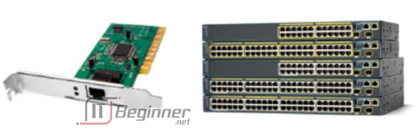
Modular Switches
Modular switches offer more flexibility in their configuration. Modular switches typically come with different sized chassis that allow for the installation of different numbers of modular line cards. The line cards actually contain the ports. The line card fits into the switch chassis like expansion cards fit into a PC. The larger the chassis, the more modules it can support. As you can see in the figure, there can be many different chassis sizes to choose from. If you bought a modular switch with a 24-port line card, you could easily add an additional 24 port line card, to bring the total number of ports up to 48.
Figure 2 displays examples of fixed configuration, modular, and stackable configuration switches.
[tabs type=”horizontal”]
[tabs_head]
[tab_title]Power over Ethernet (PoE)[/tab_title]
[tab_title]Switch Form Factors[/tab_title]
[/tabs_head]
[tab]
[/tab]
[tab]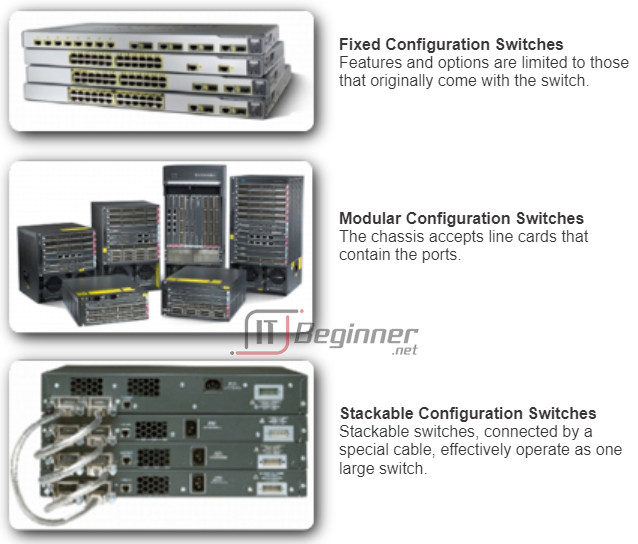 [/tab]
[/tabs]
5.3.2.2 Module Options for Cisco Switch Slots
The Cisco switch product lines are widely deployed globally, in large part due to the flexibility they provide for add-on options. Not only does the Cisco IOS have the richest set of features available relative to any other network operating system, but the IOS is tailor fit to each Cisco networking device, switches in particular.
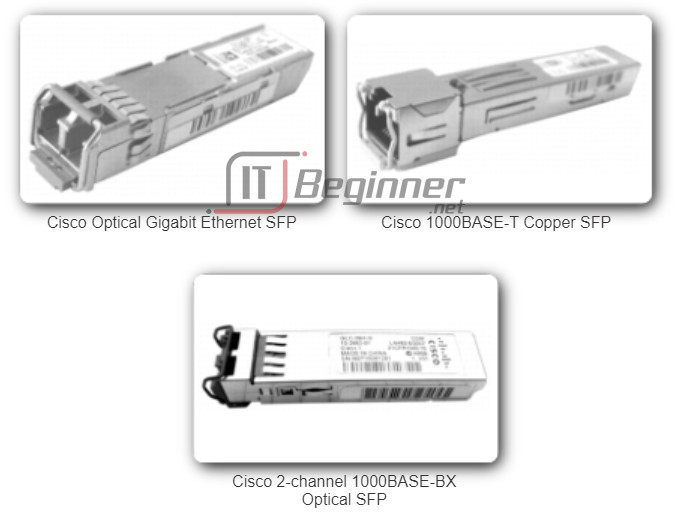
To illustrate the options available, which are literally too voluminous to list here, we focus on the Catalyst 3560 switches. The Catalyst 3560 switches have Switch Form-Factor Pluggable (SFP) ports that support a number of SFP transceiver modules. Here is a list of the SFP modules supported on one or more types of 3560 switches:
Fast Ethernet SFP Modules –
- 100BASE-FX (multimode fiber-optic (MMF)) for 2 kilometers (km)
- 100BASE-LX10 (single-mode fiber-optic (SMF)) for 2km
- 100BASE-BX10 (SMF) for 10 km
- 100BASE-EX (SMF) for 40 km
- 100BASE-ZX (SMF) for 80 km
Gigabit Ethernet SFP Modules –
- 1000BASE-SX 50/62.5 μm (MMF) up to 550/220 m
- 1000BASE-LX/LH (SMF/MMF) up to 10/0.550 k
- 1000BASE-ZX (SMF) up to 70 km
- 1000BASE-BX10-D&1000BASE-BX10-U (SMF) up to 10 km
- 1000BASE-T (copper wire transceiver)
10 Gigabit Ethernet SFP Modules –
- 10G-SR (MMF) up 400 m
- 10G-SR-X (MMF) up to 400 m (supporting extended temperature range)
- 10G-LRM (MMF) up to 220 m
- FET-10G (MMF) up to 100 m (for Nexus fabric uplinks)
- 10G-LR (SMF) up to 10 km
- 10G-LR-X (SMF) up to 10 km (supporting extended temperature range)
- 10G-ER (SMF) up to 40 km
- 10G-ZR (SMF) up to 80 km
- Twinax (copper wire transceiver) up to 10 m
- Active Optical up to 10 m (for intra/inter-rack connections)
40 Gigabit Ethernet and 100 Gigabit Ethernet modules are supported on high-end Cisco devices, such as the Catalyst 6500, the CRS router, the ASR 9000 series router, and the Nexus 7000 series switch.
5.3.3 Layer 3 Switching
5.3.3.1 Layer 2 versus Layer 3 Switching
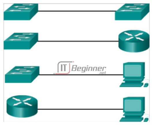
In addition to determining the various switch form factors, it may also be necessary to choose between a Layer 2 LAN switch and a Layer 3 switch.
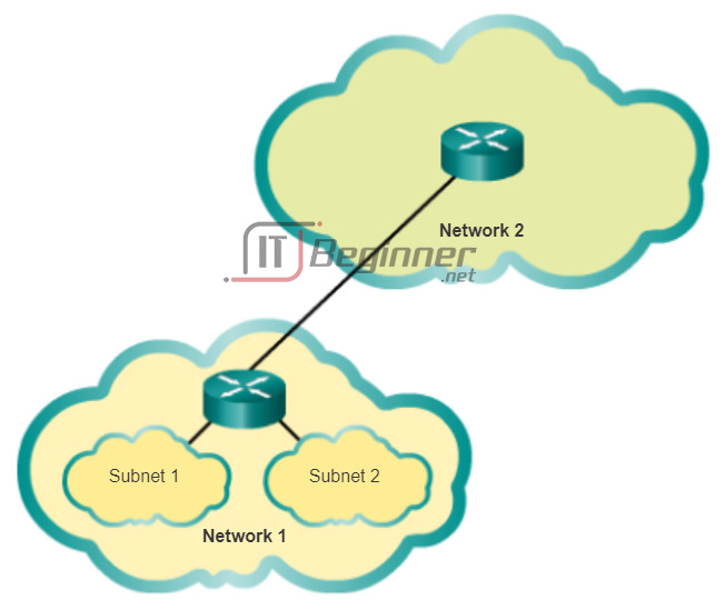
Recall that a Layer 2 LAN switch performs switching and filtering based only on the OSI data link layer (Layer 2) MAC address and depends upon routers to pass data between independent IP subnetworks (see Figure 1).
As shown in Figure 2, a Layer 3 switch, such as the Catalyst 3560, functions similarly to a Layer 2 switch, such as the Catalyst 2960, but instead of using only the Layer 2 MAC address information for forwarding decisions, a Layer 3 switch can also use IP address information. Instead of only learning which MAC addresses are associated with each of its ports, a Layer 3 switch can also learn which IP addresses are associated with its interfaces. This allows the Layer 3 switch to direct traffic throughout the network based on IP address information as well.
Layer 3 switches are also capable of performing Layer 3 routing functions, reducing the need for dedicated routers on a LAN. Because Layer 3 switches have specialized switching hardware, they can typically route data as quickly as they can switch.
[tabs type=”horizontal”]
[tabs_head]
[tab_title]Layer 2 Switching[/tab_title]
[tab_title]Layer 3 Switching[/tab_title]
[/tabs_head]
[tab]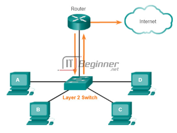 [/tab]
[tab]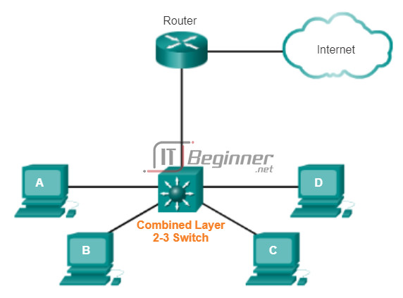 [/tab]
[/tabs]
5.3.3.2 Cisco Express Forwarding
Cisco devices which support Layer 3 switching utilize Cisco Express Forwarding (CEF). This forwarding method is quite complex, but fortunately, like any good technology, is carried out in large part “behind the scenes”. Normally very little CEF configuration is required on a Cisco device.
Basically, CEF decouples the usual strict interdependence between Layer 2 and Layer 3 decision making. What makes forwarding IP packets slow is the constant referencing back-and-forth between Layer 2 and Layer 3 constructs within a networking device. So, to the extent that Layer 2 and Layer 3 data structures can be decoupled, forwarding is accelerated.
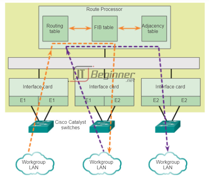
The two main components of CEF operation are the:
- Forwarding Information Base (FIB)
- Adjacency tables
The FIB is conceptually similar to a routing table. A router uses the routing table to determine best path to a destination network based on the network portion of the destination IP address. With CEF, information previously stored in the route cache is, instead, stored in several data structures for CEF switching. The data structures provide optimized lookup for efficient packet forwarding. A networking device uses the FIB lookup table to make destination-based switching decisions without having to access the route cache.
The FIB is updated when changes occur in the network and contains all routes known at the time.
Adjacency tables maintain Layer 2 next-hop addresses for all FIB entries.
The separation of the reachability information (in the FIB table) and the forwarding information (in the adjacency table), provides a number of benefits:
- The adjacency table can be built separately from the FIB table, allowing both to be built without any packets being process switched.
- The MAC header rewrite used to forward a packet is not stored in cache entries, so changes in a MAC header rewrite string do not require invalidation of cache entries.
CEF is enabled by default on most Cisco devices that perform Layer 3 switching.
5.3.3.3 Types of Layer 3 Interfaces
Cisco networking devices support a number of distinct types of Layer 3 interfaces. A Layer 3 interface is one that supports forwarding IP packets toward a final destination based on the IP address.
The major types of Layer 3 interfaces are:
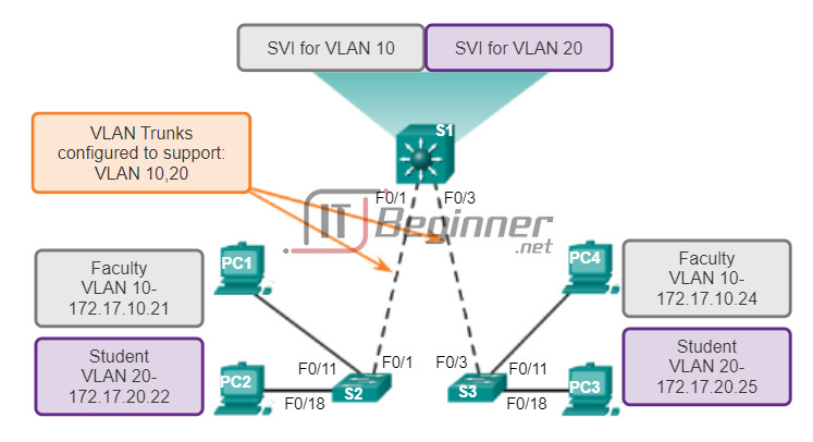
- Switch Virtual Interface (SVI) – Logical interface on a switch associated with a virtual local area network (VLAN).
- Routed Port – Physical port on a Layer 3 switch configured to act as a router port.
- Layer 3 EtherChannel – Logical interface on a Cisco device associated with a bundle of routed ports.
As shown previously, an SVI for the default VLAN (VLAN1) must be enabled to provide IP host connectivity to the switch and permit remote switch administration. SVIs must also be configured to allow routing between VLANs. As stated, SVIs are logical interfaces configured for specific VLANs; to route between two or more VLANs, each VLAN must have a separate SVI enabled.
Routed ports enable (Layer 3) Cisco switches to effectively serve as routers. Each port on such a switch can be configured as a port on an independent IP network.
Layer 3 EtherChannels are used to bundle Layer 3 Ethernet links between Cisco devices in order to aggregate bandwidth, typically on uplinks.
Note: In addition to SVIs and L3 EtherChannels, other logical interfaces on Cisco devices include loopback interfaces and tunnel interfaces.
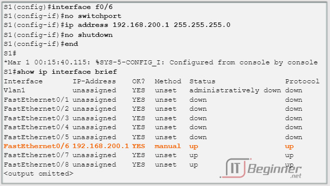
5.3.3.4 Configuring a Routed Port on a Layer 3 Switch
A switch port can be configured to be a Layer 3 routed port and behave like a regular router interface. Specifically, a routed port:
- Is not associated with a particular VLAN.
- Can be configured with a Layer 3 routing protocol.
- Is a Layer 3 interface only and does not support Layer 2 protocol.
Configure routed ports by putting the interface into Layer 3 mode with the no switchport interface configuration command. Then assign an IP address to the port. That’s it!
You will learn more about the functions of routing in the next chapter.
5.3.3.5 Packet Tracer – Configure Layer 3 Switches
The Network Administrator is replacing the current router and switch with a new Layer 3 switch. As the Network Technician, it is your job to configure the switch and place it into service. You will be working after hours to minimize disruption to the business.
Packet Tracer – Configure Layer 3 Switches Instructions ./.
Packet Tracer – Configure Layer 3 Switches – PKA ./.
5.4 Summary
5.4.1 Summary
5.4.1.1 Activity – MAC and Choose…
Note: This activity can be completed individually, in small groups, or in a full-classroom learning environment.
Please view the video located at the following link:
http://www.netevents.tv/video/bob-metcalfe-the-history-of-ethernet
Topics discussed include not only where we have come from in Ethernet development, but where we are going with Ethernet technology (a futuristic approach).
After viewing the video and comparing its contents to Chapter 5, go to the web and search for information about Ethernet. Use a constructivist approach:
- What did Ethernet look like when it was first developed?
- How has Ethernet stayed the same over the past 25 years or so, and what changes are being made to make it more useful/applicable to today’s data transmission methods?
Collect three pictures of old, current, and future Ethernet physical media and devices (focus on switches) – share these pictures with the class and discuss:
- How have Ethernet physical media and intermediary devices changed?
- How have Ethernet physical media and intermediary devices stayed the same?
- How will Ethernet change in the future?
Class Activity – MAC and Choose Instructions ./.
5.4.1.2 Summary
Ethernet is the most widely used LAN technology today. It is a family of networking technologies that are defined in the IEEE 802.2 and 802.3 standards. Ethernet standards define both the Layer 2 protocols and the Layer 1 technologies. For the Layer 2 protocols, as with all 802 IEEE standards, Ethernet relies on the two separate sublayers of the data link layer to operate, the Logical Link Control (LLC) and the MAC sublayers.
At the data link layer, the frame structure is nearly identical for all speeds of Ethernet. The Ethernet frame structure adds headers and trailers around the Layer 3 PDU to encapsulate the message being sent.
There are two styles of Ethernet framing: IEEE 802.3 Ethernet standard and the DIX Ethernet standard which is now referred to Ethernet II. The most significant difference between the two standards is the addition of a Start Frame Delimiter (SFD) and the change of the Type field to a Length field in the 802.3. Ethernet II is the Ethernet frame format used in TCP/IP networks. As an implementation of the IEEE 802.2/3 standards, the Ethernet frame provides MAC addressing and error checking.
The Layer 2 addressing provided by Ethernet supports unicast, multicast, and broadcast communications. Ethernet uses the Address Resolution Protocol to determine the MAC addresses of destinations and map them against known network layer addresses.
Each node on an IP network has both a MAC address and an IP address. The node must use its own MAC and IP addresses in the source fields and must provide both a MAC address and an IP address for the destination. While the IP address of the destination will be provided by a higher OSI layer, the sending node must find the MAC address of the destination for a given Ethernet link. This is the purpose of ARP.
ARP relies on certain types of Ethernet broadcast messages and Ethernet unicast messages, called ARP requests and ARP replies. The ARP protocol resolves IPv4 addresses to MAC addresses and maintains a table of mappings.
On most Ethernet networks, end devices are typically connected, in a point-to-point basis, to a Layer 2 LAN switch. A Layer 2 LAN switch performs switching and filtering based only on the OSI data link layer (Layer 2) MAC address. A Layer 2 switch builds a MAC address table that it uses to make forwarding decisions. Layer 2 switches depend on routers to pass data between independent IP subnetworks.
Layer 3 switches are also capable of performing Layer 3 routing functions, reducing the need for dedicated routers on a LAN. Because Layer 3 switches have specialized switching hardware, they can typically route data as quickly as they can switch.