Introduction to Networks Instructor Materials – Chapter 9: Subnetting IP Networks
9.0 Subnetting IP Networks
9.0.1 Introduction
9.0.1.1 Introduction
Designing, implementing and managing an effective IP addressing plan ensures that networks can operate effectively and efficiently. This is especially true as the number of host connections to a network increases. Understanding the hierarchical structure of the IP address and how to modify that hierarchy in order to more efficiently meet routing requirements is an important part of planning an IP addressing scheme.
In the original IPv4 address, there are two levels of hierarchy: a network and a host. These two levels of addressing allow for basic network groupings that facilitate in routing packets to a destination network. A router forwards packets based on the network portion of an IP address; once the network is located, the host portion of the address allows for identification of the destination device.
However, as networks grow, with many organizations adding hundreds, and even thousands of hosts to their network, the two-level hierarchy is insufficient.
Subdividing a network adds a level to the network hierarchy, creating, in essence, three levels: a network, a subnetwork, and a host. Introducing an additional level to the hierarchy creates additional sub-groups within an IP network that facilities faster packet delivery and added filtration, by helping to minimize ‘local’ traffic.
This chapter examines, in detail, the creation and assignment of IP network and subnetwork addresses through the use of the subnet mask.
Upon completion of this chapter you will be able to:
- Explain why routing is necessary for hosts on different subnets to communicate.
- Describe IP as a communication protocol used to identify a single device on a network.
- Given a network and subnet mask, calculate the number of host addresses available.
- Calculate the necessary subnet mask in order to accommodate a given number of hosts.
- Describe the benefits of variable length subnet masking (VLSM).
- Design and implement a hierarchical addressing scheme.
- Explain how IPv6 address assignments are implemented in a business network.
9.0.1.2 Activity – Call Me!
In this chapter, you will be learning how devices can be grouped into subnets, or smaller network groups, from a large network.
In this modeling activity, you are asked to think about a number you probably use every day, a number such as your telephone number. As you complete the activity, think about how your telephone number compares to strategies that network administrators might use to identify hosts for efficient data communication.
Complete the two questions listed below and record your answers. Save the two sections in either hard- or soft-copy format to use later for class discussion purposes.
- Explain how your smartphone or landline telephone number is divided into identifying groups of numbers. Does your telephone number use an area code? An ISP identifier? A city, state, or country code?
- In what ways does separating your telephone number into managed parts assist in contacting or communicating with others?
Class Activity – Call me! Instructions ./.
9.1 Subnetting an IPv4 Network
9.1.1 Network Segmentation
9.1.1.1 Reasons for Subnetting
In early network implementations, it was common for organizations to have all computers and other networked devices connected to a single IP network. All devices in the organization were assigned an IP address with a matching network ID. This type of configuration is known as a flat network design. In a small network, with a limited number of devices, a flat network design is not problematic. However, as the network grows, this type of configuration can create major issues.
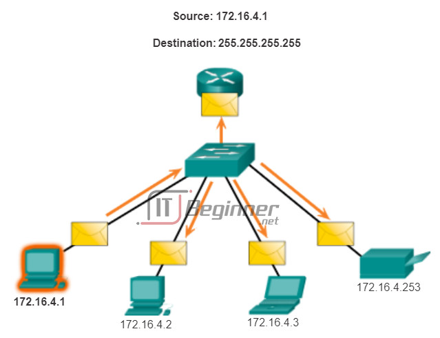
Consider how on an Ethernet LAN, devices use broadcasts to locate needed services and devices. Recall that a broadcast is sent to all hosts on an IP network. The Dynamic Host Configuration Protocol (DHCP) is an example of a network service that depends on broadcasts. Devices send broadcasts across the network to locate the DHCP server. On a large network, this could create a significant amount of traffic slowing network operations. Additionally, because a broadcast is addressed to all devices, all devices must accept and process the traffic, resulting in increased device processing requirements. If a device must process a significant amount of broadcasts, it could even slow device operations. For reasons such as these, larger networks must be segmented into smaller sub-networks, keeping them localized to smaller groups of devices and services.
The process of segmenting a network, by dividing it into multiple smaller network spaces, is called subnetting. These sub-networks are called subnets. Network administrators can group devices and services into subnets that are determined by geographic location (perhaps the 3rd floor of a building), by organizational unit (perhaps the sales department), by device type (printers, servers, WAN), or any other division that makes sense for the network. Subnetting can reduce overall network traffic and improve network performance.
Note: A subnet is equivalent to a network and these terms can be used interchangeably. Most networks are a subnet of some larger address block.
9.1.1.2 Communication Between Subnets
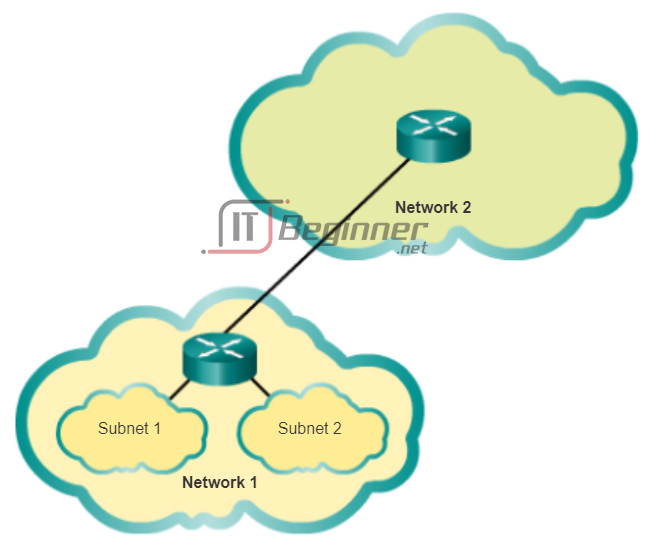
A router is necessary for devices on different networks to communicate. Devices on a network use the router interface attached to their LAN as their default gateway. Traffic that is destined for a device on a remote network will be processed by the router and forwarded toward the destination. To determine if traffic is local or remote, the router uses the subnet mask.
In a subnetted network space, this works exactly the same way. As shown in the figure, subnetting creates multiple logical networks from a single address block or network address. Each subnet is treated as a separate network space. Devices on the same subnet must use an address, subnet mask, and default gateway that correlates to the subnet that they are a part of.
Traffic cannot be forwarded between subnets without the use of a router. Every interface on the router must have an IPv4 host address that belongs to the network or subnet to which the router interface is connected.
9.1.2 IP Subnetting is FUNdamental
9.1.2.1 The Plan
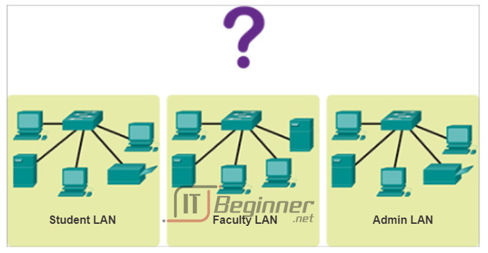
As shown in the figure, planning network subnets requires examination of both the needs of an organization’s network usage, and how the subnets will be structured. Doing a network requirement study is the starting point. This means looking at the entire network and determining the main sections of the network and how they will be segmented. The address plan includes deciding the needs for each subnet in terms of size, how many hosts per subnet, how host addresses will be assigned, which hosts will require static IP addresses and which hosts can use DHCP for obtaining their addressing information.
The size of the subnet involves planning the number of hosts that will require IP host addresses in each subnet of the subdivided private network. For example in a campus network design you might consider how many hosts are needed in the Administrative LAN, how many in the Faculty LAN and how many in the Student LAN. In a home network, a consideration might be done by the number of hosts in the Main House LAN and the number of hosts in the Home Office LAN.
As discussed earlier, the private IP address range used on a LAN is the choice of the network administrator and needs careful consideration to be sure that enough host address will be available for the currently known hosts and for future expansion. Remember the private IP address ranges are:
- 10.0.0.0 with a subnet mask of 255.0.0.0
- 172.16.0.0 with a subnet mask of 255.240.0.0
- 192.168.0.0 with a subnet mask of 255.255.0.0
Knowing your IP address requirements will determine the range or ranges of host addresses you implement. Subnetting the selected private IP address space will provide the host addresses to cover your network needs.
Public addresses used to connect to the Internet are typically allocated from a service provider. So while the same principles for subnetting would apply, this is not generally the responsibility of the organization’s network administrator.
9.1.2.2 The Plan – Address Assignment
Create standards for IP address assignments within each subnet range. For example:
- Printers and servers will be assigned static IP addresses
- User will receive IP addresses from DHCP servers using /24 subnets
- Routers are assigned the first available host addresses in the range
Two very important factors that will lead to the determination of which private address block is required, are the number of subnets required and the maximum number of hosts needed per subnet. Each of these address blocks will allow you to appropriately allocate hosts based on the given size of a network and its required hosts currently and in the near future. Your IP space requirements will determine the range or ranges of hosts you implement.
In the upcoming examples you will see subnetting based on address blocks that have subnet masks of 255.0.0.0, 255.255.0.0, and 255.255.255.0.

9.1.3 Subnetting an IPv4 Network
9.1.3.1 Basic Subnetting
Every network address has a valid range of host addresses. All devices attached to the same network will have an IPv4 host address for that network and a common subnet mask or network prefix.
The prefix and the subnet mask are different ways of representing the same thing – the network portion of an address.
IPv4 subnets are created by using one or more of the host bits as network bits. This is done by extending the mask to borrow some of the bits from the host portion of the address to create additional network bits. The more host bits borrowed, the more subnets that can be defined. For each bit borrowed, the number of subnetworks available is doubled. For example, if 1 bit is borrowed, 2 subnets can be created. If 2 bits, 4 subnets are created, if 3 bits are borrowed, 8 subnets are created, and so on. However, with each bit borrowed, fewer host addresses are available per subnet.
Bits can only be borrowed from the host portion of the address. The network portion of the address is allocated by the service provider and cannot be changed.
Note: In the examples in the figures, only the last octet is shown in binary because only bits from the host portion can be borrowed.
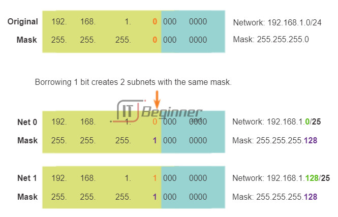
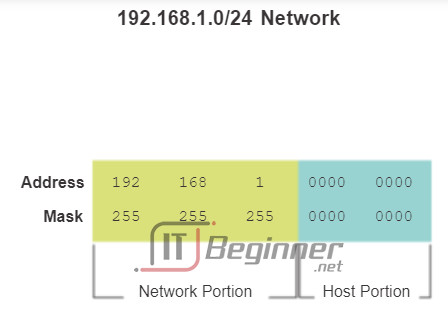
As shown in Figure 1, the 192.168.1.0/24 network has 24 bits in the network portion and 8 bits in the host portion, which is indicated with the subnet mask 255.255.255.0 or /24 notation. With no subnetting, this network supports a single LAN interface. If an additional LAN is needed, the network would need to be subnetted.
In Figure 2, 1 bit is borrowed from the most significant bit (leftmost bit) in the host portion, thus extending the network portion to 25 bits. This creates 2 subnets identified by using a 0 in the borrowed bit for the first network and a 1 in the borrowed bit for the second network. The subnet mask for both networks uses a 1 in the borrowed bit position to indicate that this bit is now part of the network portion.
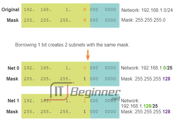
As shown in Figure 3, when we convert the binary octet to decimal we see that the first subnet address is 192.168.1.0 and the second subnet address is 192.168.1.128. Because a bit has been borrowed, the subnet mask for each subnet is 255.255.255.128 or /25.
[tabs type=”horizontal”]
[tabs_head]
[tab_title]Figure 1[/tab_title]
[tab_title]Figure 2[/tab_title]
[tab_title]Figure 3[/tab_title]
[/tabs_head]
[tab]
[/tab]
[tab]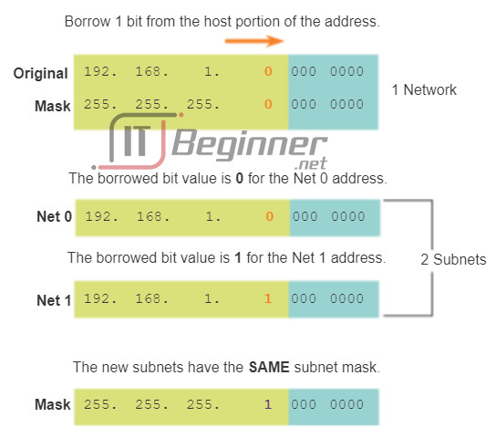 [/tab]
[tab]
[/tab]
[/tabs]
9.1.3.2 Subnets in Use
In the previous example, the 192.168.1.0/24 network was subnetted to create two subnets:
192.168.1.0/25
192.168.1.128/25
In Figure 1, notice that router R1 has two LAN segments attached to its GigabitEthernet interfaces. The subnets will be used for the segments attached to these interfaces. To serve as the gateway for devices on the LAN, each of the router interfaces must be assigned an IP address within the range of valid addresses for the assigned subnet. It is common practice to use the first or last available address in a network range for the router interface address.
The first subnet, 192.168.1.0/25, is used for the network attached to GigabitEthernet 0/0 and the second subnet, 192.168.1.128/25, is used for the network attached to GigabitEthernet 0/1. To assign an IP address for each of these interfaces, it is necessary to determine the range of valid IP addresses for each subnet.
The following are guidelines for each of the subnets:
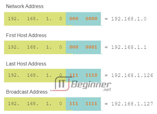
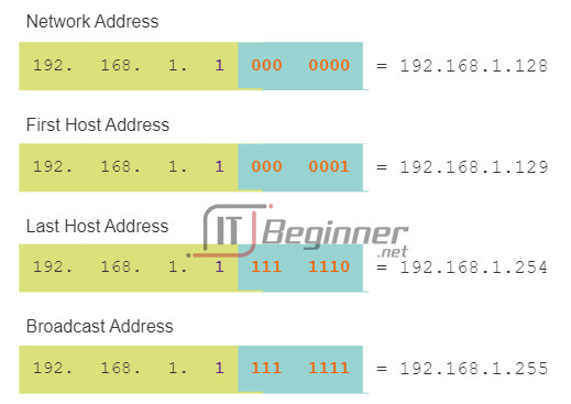
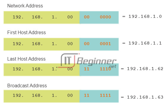
- Network address – All 0 bits in the host portion of the address.
- First host address – All 0 bits plus a right-most 1 bit in the host portion of the address.
- Last host address – All 1 bits plus a right-most 0 bit in the host portion of the address.
- Broadcast address – All 1 bits in the host portion of the address.
As shown in Figure 2, the first host address for the 192.168.1.0/25 network is 192.168.1.1, and the last host address is 192.168.1.126. Figure 3 shows that the first host address for the 192.168.1.128/25 network is 192.168.1.129, and the last host address is 192.168.1.254.
To assign the first host address in each subnet to the router interface for that subnet, use the ip address command in interface configuration mode as shown in Figure 4. Notice that each subnet uses the subnet mask of 255.255.255.128 to indicate that the network portion of the address is 25 bits.
A host configuration for the 192.168.1.128/25 network is shown in Figure 5. Notice that the gateway IP address is the address configured on the G0/1 interface of R1, 192.168.1.129, and the subnet mask is 255.255.255.128.
[tabs type=”horizontal”]
[tabs_head]
[tab_title]Figure 1[/tab_title]
[tab_title]Figure 2[/tab_title]
[tab_title]Figure 3[/tab_title]
[tab_title]Figure 4[/tab_title]
[tab_title]Figure 5[/tab_title]
[/tabs_head]
[tab]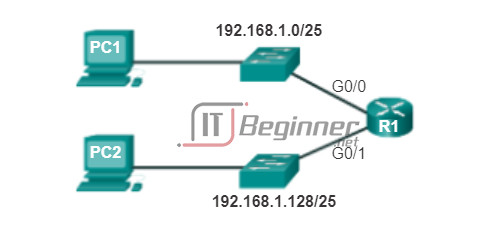 [/tab]
[tab]
[/tab]
[tab]
[/tab]
[tab]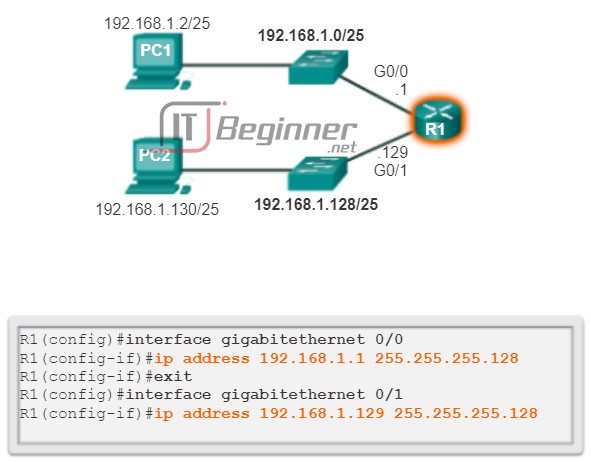 [/tab]
[tab]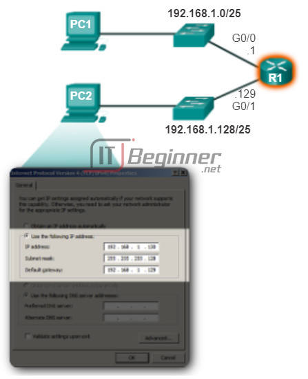 [/tab]
[/tabs]
9.1.3.3 Subnetting Formulas
Calculating Subnets
Use this formula to calculate the number of subnets:
2^n (where n = the number of bits borrowed)
As shown in Figure 1, for the 192.168.1.0/25 example, the calculation looks like this:
2^1 = 2 subnets
Calculating Hosts
Use this formula to calculate the number of hosts per network:
2^n (where n = the number of bits remaining in the host field)
As shown in Figure 2, for the 192.168.1.0/25 example, the calculation looks like this:
2^7 = 128
Because hosts cannot use the network address or broadcast address from a subnet, 2 of these addresses are not valid for host assignment. This means that each of the subnets has 126 (128-2) valid host addresses.
So in this example, borrowing 1 host bit toward the network results in creating 2 subnets, and each subnet can have a total of 126 hosts assigned.
[tabs type=”horizontal”]
[tabs_head]
[tab_title]Calculate Number of Subnets[/tab_title]
[tab_title]Calculate Number of Hosts[/tab_title]
[/tabs_head]
[tab]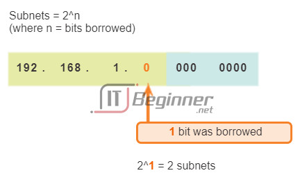 [/tab]
[tab]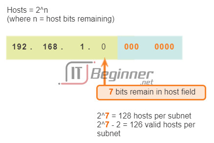 [/tab]
[/tabs]
9.1.3.4 Creating 4 Subnets
Consider an internetwork that requires three subnets.
Using the same 192.168.1.0/24 address block, host bits must be borrowed to create at least 3 subnets. Borrowing a single bit would only provide 2 subnets. To provide more networks, more host bits must be borrowed. Calculate the number of subnets created if 2 bits are borrowed using the formula 2^number of bits borrowed:
2^2 = 4 subnets
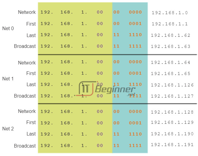
Borrowing 2 bits creates 4 subnets, as shown in Figure 1.
Recall that the subnet mask must change to reflect the borrowed bits. In this example, when 2 bits are borrowed, the mask is extended 2 bits into the last octet. In decimal, the mask is represented as 255.255.255.192, because the last octet is 1100 0000 in binary.
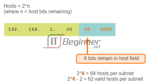
Host Calculation
To calculate the number of hosts, examine the last octet. After borrowing 2 bits for the subnet, there are 6 host bits remaining.
Apply the host calculation formula as shown in Figure 2.
2^6 = 64
But remember that all 0 bits in the host portion of the address is the network address, and all 1s in the host portion is a broadcast address. Therefore, there are only 62 host addresses that are actually available for each subnet.
As shown in Figure 3, the first host address for the first subnet is 192.168.1.1 and the last host address is 192.168.1.62. Figure 4 shows the ranges for subnets 0 – 2. Remember that each host must have a valid IP address within the range defined for that network segment. The subnet assigned to the router interface will determine which segment a host belongs to.
In Figure 5 a sample configuration is shown. In this configuration, the first network is assigned to the GigabitEthernet 0/0 interface, the second network is assigned to the GigabitEthernet 0/1 interface, and the third network is assigned to the Serial 0/0/0 network.
Again, using a common addressing plan, the first host address in the subnet is assigned to the router interface. Hosts on each subnet will use the address of the router interface as the default gateway address.
- PC1 (192.168.1.2/26) will use 192.168.1.1 (G0/0 interface address of R1) as its default gateway address
- PC2 (192.168.1.66/26) will use 192.168.1.65 (G0/1 interface address of R1) as its default gateway address
Note: All devices on the same subnet will have a host IPv4 address from the range of host addresses and will use the same subnet mask.
[tabs type=”horizontal”]
[tabs_head]
[tab_title]Figure 1[/tab_title]
[tab_title]Figure 2[/tab_title]
[tab_title]Figure 3[/tab_title]
[tab_title]Figure 4[/tab_title]
[tab_title]Figure 5[/tab_title]
[/tabs_head]
[tab]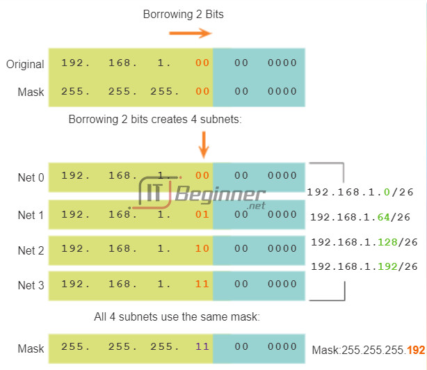 [/tab]
[tab]
[/tab]
[tab]
[/tab]
[tab]
[/tab]
[tab]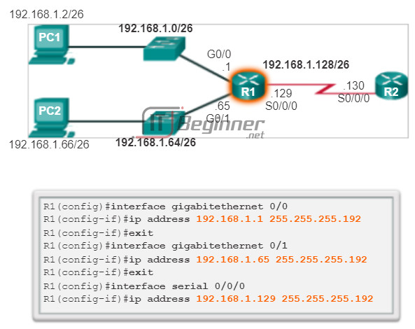 [/tab]
[/tabs]
9.1.3.5 Creating 8 Subnets
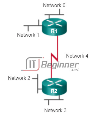
Next, consider an internetwork that requires five subnets as shown in Figure 1.
Using the same 192.168.1.0/24 address block, host bits must be borrowed to create at least 5 subnets. Borrowing 3 bits would only provide 4 subnets as seen in the previous example. To provide more networks, more host bits must be borrowed. Calculate the number of subnets created if 3 bits are borrowed using the formula:
2^3 = 8 subnets
As shown in Figures 2 and 3, borrowing 3 bits creates 8 subnets. When 3 bits are borrowed, the subnet mask is extended 3 bits into the last octet (/27), resulting in a subnet mask of 255.255.255.224. All devices on these subnets will use the subnet mask 255.255.255.224 mask (/27).
Host Calculation
To calculate the number of hosts, examine the last octet. After borrowing 3 bits for the subnet, there are 5 host bits remaining.
Apply the host calculation formula:
2^5 = 32, but subtract 2 for the all 0s in the host portion (network address) and all 1s in the host portion (broadcast address).
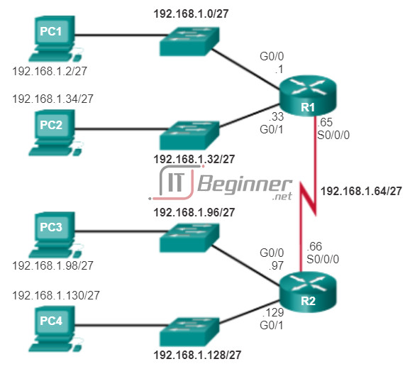
The subnets are assigned to the network segments required for the topology as shown in Figure 4.
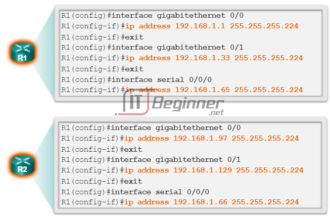
Again, using a common addressing plan, the first host address in the subnet is assigned to the router interface, as shown in Figure 5. Hosts on each subnet will use the address of the router interface as the default gateway address.
- PC1 (192.168.1.2/27) will use 192.168.1.1 address as its default gateway address.
- PC2 (192.168.1.34/27) will use 192.168.1.33 address as its default gateway address.
- PC3 (192.168.1.98/27) will use 192.168.1.97 address as its default gateway address.
- PC4 (192.168.1.130/27) will use 192.168.1.129 address as its default gateway address.
[tabs type=”horizontal”]
[tabs_head]
[tab_title]Figure 1[/tab_title]
[tab_title]Figure 2[/tab_title]
[tab_title]Figure 3[/tab_title]
[tab_title]Figure 4[/tab_title]
[tab_title]Figure 5[/tab_title]
[/tabs_head]
[tab]
[/tab]
[tab]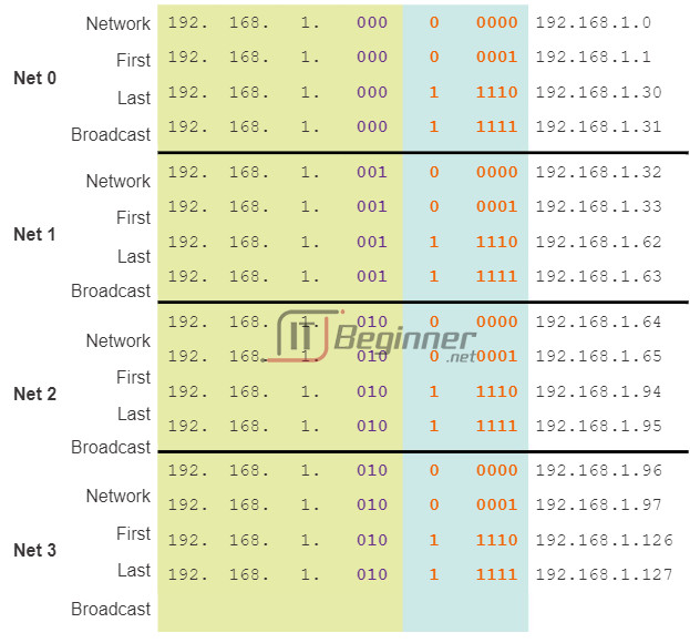 [/tab]
[tab]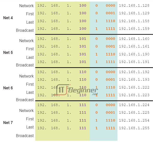 [/tab]
[tab]
[/tab]
[tab]
[/tab]
[/tabs]
9.1.3.6 Activity – Determining the Network Address – Basic
9.1.3.7 Activity – Calculate the Number of Hosts – Basic
9.1.3.8 Activity – Determining the Valid Addresses for Hosts – Basics
9.1.3.9 Activity – Calculate the Subnet Mask
9.1.3.10 Creating 100 Subnets with a /16 prefix
In the previous examples, we considered an internetwork that required 3 subnets and one that required 5 subnets. To achieve the goal of creating four subnets we borrowed 2 bits from the 8 hosts bits available with an IP address that has a default mask of 255.255.255.0, or a /24 prefix. The resulting subnet mask was 255.255.255.192, and a total of 4 possible subnets were created. Applying the host calculation formula of 2^6-2, we determined that on each one of those 4 subnets we could have 62 host addresses to assign to nodes.
To acquire 5 subnets, we borrowed 3 bits from the 8 hosts bits available with an IP address that has a default mask of 255.255.255.0, or a /24 prefix. In borrowing those 3 bits from the host portion of the address, we left 5 hosts bits remaining. The resulting subnet mask was 255.255.255.224, with a total of 8 subnets create, and 30 host addresses per subnet.
Consider large organizations or campuses with an internetwork that requires 100 subnets. Just as in the previous examples, to achieve the goal of creating 100 subnets, we must borrow bits from the host portion of the IP address of the existing internetwork. As before, to calculate the number of subnets, we must look at the number of available host bits and use the subnet calculation formula 2^number of bits borrowed minus 2. Using the IP address of the last example, 192.168.10.0/24, we have 8 host bits; to create 100 subnets, we must borrow 7 bits.
Calculate the number of subnets if 7 bits are borrowed: 2^7=128 subnets.
However, borrowing 7 bits will leave just one remaining host bit and if we apply the host calculation formula, the result would be no hosts on these subnets. Calculate the number of hosts if one bit is remaining: 2^1=2, then subtract 2 for the network address and the network broadcast; the result 0 hosts (2^1-2=0).
In a situation requiring a larger number of subnets, an IP network is required that has more hosts bits to borrow from, such as an IP address with a default subnet mask of /16, or 255.255.0.0. Addresses that have a range of 128 – 191 in the first octet have a default mask of 255.255.0.0, or /16. Addresses in this range have 16 bits in the network portion and 16 bits in the host portion. These 16 bits are the bits that are available to borrow for creating subnets.
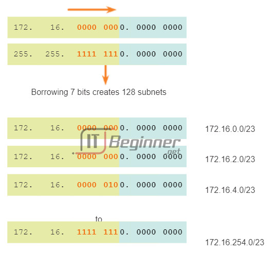
Using a new IP address of 172.16.0.0/16 address block, host bits must be borrowed to create at least 100 subnets. Starting from left to right with the first available host bit, we will borrow a single bit at a time until we reach the number of bits necessary to create 100 subnets. Borrowing 1 bit, we would create 2 subnets, borrowing 2 bits, we would create 4 subnets, 3 bits 8 subnets, and so on. Calculate the number of subnets created if 7 bits are borrowed using the formula 2^number of bits borrowed:
2^7 = 128 subnets
Borrowing 7 bits creates 128 subnets, as shown in the figure.
Recall that the subnet mask must change to reflect the borrowed bits. In this example, when 7 bits are borrowed, the mask is extended 7 bits into the third octet. In decimal, the mask is represented as 255.255.254.0, or a /23 prefix, because the third octet is 11111110 in binary and the fourth octet is 00000000 in binary. Subnetting will be done in the third octet, with the host bits in the third and fourth octets.
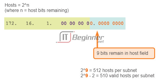
9.1.3.11 Calculating the Hosts
Host Calculation
To calculate the number of hosts, examine the third and fourth octet. After borrowing 7 bits for the subnet, there is one host bit remaining in the third octet and there are 8 host bits remaining in the fourth octet.
Apply the host calculation formula as shown in Figure 1.
2^9 = 512
But remember that all 0 bits in the host portion of the address is the network address, and all 1s in the host portion is a broadcast address. Therefore, there are only 510 host addresses that are actually available for each subnet.
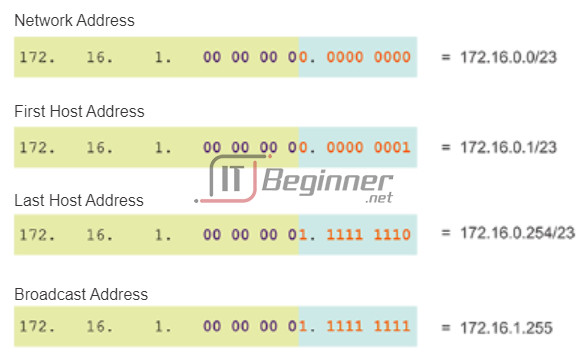
As showing in Figure 2, the first host address for the first subnet is 172.16.0.1 and the last host address is 172.16.1.254. Remember that each host must have a valid IP address within the range defined for that network segment. The subnet assigned to the router interface will determine which segment a host belongs to.
Reminder:
Bits can only be borrowed from the host portion of the address. The network portion of the address is allocated by the service provider and cannot be changed. So organizations that required a significant number of subnets were required to communicate this need to their ISP so that the ISP would allocate an IP address with a default mask with enough bits to create the needed subnets.
[tabs type=”horizontal”]
[tabs_head]
[tab_title]Figure 1[/tab_title]
[tab_title]Figure 2[/tab_title]
[/tabs_head]
[tab]
[/tab]
[tab]
[/tab]
[/tabs]
9.1.3.12 Calculating the Hosts
There are some organizations, such as small service providers, that might need even more subnets than 100. Take for example, an organization that requires 1000 subnets. As always, in order to create subnets we must borrow bits from the host portion of the IP address of the existing internetwork. As before, to calculate the number of subnets it is necessary to look at the number of available hosts bits. A situation such as this requires that the IP address assigned by the ISP have enough host bits available to calculate 1000 subnets. IP addresses that have the range of 1-126 in the first octet have a default mask of 255.0.0.0 or /8. This means there are 8 bits in the network portion and 24 host bits available to borrow toward subnetting.
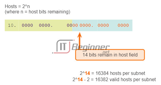
Using the 10.0.0.0/8 address block, host bits must be borrowed to create at least 1000 subnets. Starting from left to the right with the first available host bit we will borrow a single bit at a time until we reach the number of bits necessary to create 1000 subnets. Calculate the number of subnets created if 10 bits are borrowed using the formula 2^number of bits borrowed:
2^10 = 1024 subnets
Borrowing 10 bits creates 1024 subnets, as shown in Figure 1.
Recall that the subnet mask must change to reflect the borrowed bits. In this example, when 10 bits are borrowed, the mask is extended 10 bits into the third octet. In decimal, the mask is represented as 255.255.192.0 or a /18 prefix, because the third octet of the subnet mask is 11000000 in binary and the fourth octet is 00000000 in binary. Subnetting will be done in the third octet, but don’t forget about the host bits in the third and fourth octets.
Host Calculation
To calculate the number of hosts, examine the third and fourth octet. After borrowing 10 bits for the subnet, there are 6 host bits remaining in the third octet and 8 host bits remaining in the fourth octet. A total of 14 host bits remain.
Apply the host calculation formula as shown in Figure 2.
2^14 – 2 = 16382
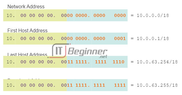
The first host address for the first subnet is 10.0.0.1 and the last host address is 10.0.63.254. Remember that each host must have a valid IP address within the range defined for that network segment. The subnet assigned to the router interface will determine which segment a host belongs to.
Note: All devices on the same subnet will have a host IPv4 address from the range of host addresses and will use the same subnet mask.
[tabs type=”horizontal”]
[tabs_head]
[tab_title]Figure 1[/tab_title]
[tab_title]Figure 2[/tab_title]
[tab_title]Figure 3[/tab_title]
[/tabs_head]
[tab]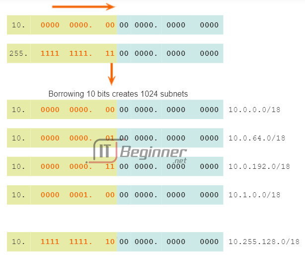 [/tab]
[tab]
[/tab]
[tab]
[/tab]
[/tabs]
9.1.3.13 Activity – Determining the Network Address – Advanced
9.1.3.14 Activity – Calculating the Number of Hosts – Advanced
9.1.3.15 Activity – Determining the Valid Addresses for Hosts – Advanced
9.1.4 Determining the Subnet Mask
9.1.4.1 Subnetting Based on Host Requirements
The decision about how many host bits to borrow to create subnets is an important planning decision. There are two considerations when planning subnets: the number of host addresses required for each network and the number of individual subnets needed. The animation shows the subnet possibilities for the 192.168.1.0 network. The selection of a number of bits for the subnet ID affects both the number of possible subnets and the number of host addresses in each subnet.
Notice that there is an inverse relationship between the number of subnets and the number of hosts. The more bits borrowed to create subnets the fewer host bits are available; therefore, fewer hosts per subnet. If more host addresses are needed, more host bits are required, resulting in fewer subnets.
Number of Hosts
When borrowing bits to create multiple subnets, you leave enough host bits for the largest subnet. The number of host addresses required in the largest subnet will determine how many bits must be left in the host portion. The formula 2^n (where n is the number the number of host bits remaining) is used to calculate how many addresses will be available on each subnet. Recall that 2 of the addresses cannot be used, so that the usable number of addresses can be calculated as 2^n-2.
9.1.4.2 Subnetting Network-Based Requirements
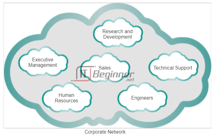
Sometimes a certain number of subnets is required, with less emphasis on the number of host addresses per subnet. This may be the case if an organization chooses to separate their network traffic based on internal structure or department setup. For example, an organization may choose to put all host devices used by employees in the Engineering department in one network, and all host devices used by management in a separate network. In this case, the number of subnets is most important in determining how many bits to borrow.
Recall the number of subnets created when bits are borrowed can be calculated using the formula 2^n (where n is the number of bits borrowed). There is no need to subtract any of the resulting subnets, as they are all usable.
The key is to balance the number of subnets needed and the number of hosts required for the largest subnet. The more bits borrowed to create additional subnets means fewer hosts available per subnet.
9.1.4.3 Subnetting to Meet Network Requirements
Every network within an organization is designed to accommodate a finite number of hosts. Basic subnetting requires enough subnets to accommodate the networks while also providing enough host addresses per subnet.
Some networks, such as point-to-point WAN links, require only two hosts. Other networks, such as a user LAN in a large building or department, may need to accommodate hundreds of hosts. Network administrators must devise the internetwork addressing scheme to accommodate the maximum number of hosts for each network. The number of hosts in each division should allow for growth in the number of hosts.
Determine the Total Number of Hosts
First, consider the total number of hosts required by the entire corporate internetwork. A block of addresses large enough to accommodate all devices in all the corporate networks must be used. These devices include end user devices, servers, intermediate devices, and router interfaces.
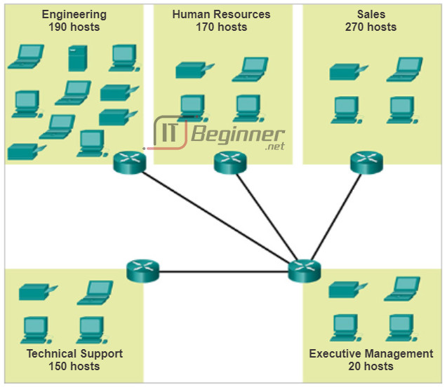
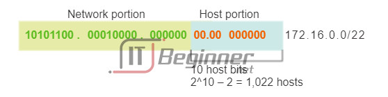
Consider the example of a corporate internetwork that must accommodate a total of 800 hosts in its five locations (see Figure 1). In this example, the service provider has allocated a network address of 172.16.0.0/22 (10 host bits). As shown in Figure 2, this will provide 1,022 host addresses, which will more than accommodate the addressing needs for this internetwork.
[tabs type=”horizontal”]
[tabs_head]
[tab_title]Figure 1[/tab_title]
[tab_title]Figure 2[/tab_title]
[/tabs_head]
[tab]
[/tab]
[tab]
[/tab]
[/tabs]
9.1.4.4 Subnetting To Meet Network Requirements, Cont.
Determine the Number and Size of the Networks
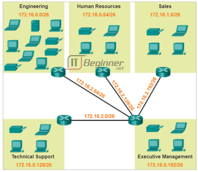
Next, consider the number of subnets required and the number of host addresses needed on each subnet. Based on the network topology consisting of 5 LAN segments and 4 internetwork connections between routers, 9 subnets are required. The largest subnet requires 40 hosts. When designing an addressing scheme, you should anticipate growth in both the number of subnets and the hosts per subnet.
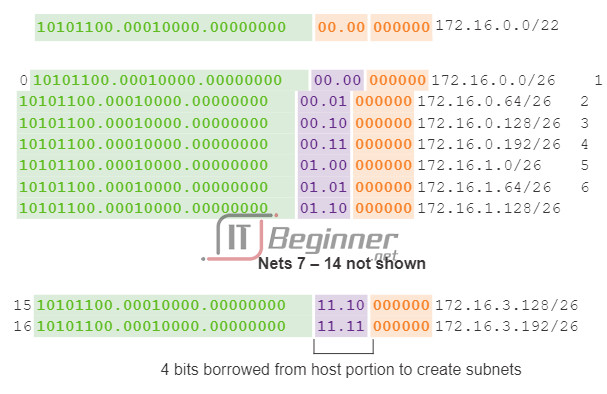
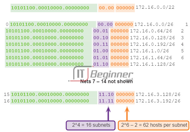
The 172.16.0.0/22 network address has 10 host bits. Because the largest subnet requires 40 hosts, a minimum of 6 host bits should be borrowed. This is determined by using this formula: 2^6 – 2 = 62 hosts. The 4 remaining host bits can be used to allocate subnets. Using the formula for determining subnets, this results in 16 subnets: 2^4 = 16. Because the example internetwork requires 9 subnets this will meet the requirement and allow for some additional growth.
When 4 bits are borrowed the new prefix length is /26 with a subnet mask of 255.255.255.192.
As shown in Figure 1, using the /26 prefix length, the 16 subnet addresses can be determined. Only the subnet portion of the address is incremented. The original 22 bits of the network address cannot change and the host portion will contain all 0 bits.
Note: Notice that because the subnet portion is in both the third and fourth octets that one or both of these values will vary in the subnet addresses.
As shown in Figure 2, the original 172.16.0.0/22 network was a single network with 10 host bits providing 1,022 usable addresses to assign to hosts. By borrowing 4 host bits, 16 subnets (0000 through 1111) can be created. Each subnet has 6 host bits or 62 usable host addresses per subnet.
As shown in Figure 3, the subnets can be assigned to the LAN segments and router-to-router connections.
[tabs type=”horizontal”]
[tabs_head]
[tab_title]Figure 1[/tab_title]
[tab_title]Figure 2[/tab_title]
[tab_title]Figure 3[/tab_title]
[/tabs_head]
[tab]
[/tab]
[tab]
[/tab]
[tab]
[/tab]
[/tabs]
9.1.4.5 Activity – Determining the Number of Bits to Borrow
9.1.4.6 Packet Tracer – Subnetting Scenario 1
In this activity, you are given the network address of 192.168.100.0/24 to subnet and provide the IP addressing for the network shown in the topology. Each LAN in the network requires enough space for, at least, 25 addresses for end devices, the switch and the router. The connection between R1 to R2 will require an IP address for each end of the link.
Packet Tracer – Subnetting Scenario 1 Instructions ./.
Packet Tracer – Subnetting Scenario 1 – PKA ./.
9.1.4.7 Packet Tracer – Subnetting Scenario 2
In this activity, you are given the network address of 172.31.1.0/24 to subnet and provide the IP addressing for the network shown in the topology. The required host addresses for each WAN and LAN link are labeled in the topology.
Packet Tracer – Subnetting Scenario 2 Instructions ./.
Packet Tracer – Subnetting Scenario 2 – PKA ./.
9.1.4.8 Lab – Calculating IPv4 Subnets
In this lab, you will complete the following objectives:
- Part 1: Determine IPv4 Address Subnetting
- Part 2: Calculate IPv4 Address Subnetting
Lab – Calculating IPv4 Subnets ./.
9.1.4.9 Lab – Subnetting Network Topologies
In this lab, you will complete the following objectives:
Parts 1 to 5, for each network topology:
- Determine the number of subnets.
- Design an appropriate addressing scheme.
- Assign addresses and subnet mask pairs to device interfaces.
- Examine the use of the available network address space and future growth potential.
Lab – Subnetting Network Topologies ./.
9.1.4.10 Lab – Researching Subnet Calculators
In this lab, you will complete the following objectives:
- Part 1: Review Available Subnet Calculators.
- Part 2: Perform Network Calculations Using a Subnet Calculator.
Lab – Researching Subnet Calculators ./.
9.1.5 Benefits of Variable Length Subnet Masking
9.1.5.1 Traditional Subnetting Wastes Addresses
Using traditional subnetting, the same number of addresses is allocated for each subnet. If all the subnets have the same requirements for the number of hosts, these fixed size address blocks would be efficient. However, most often that is not the case.
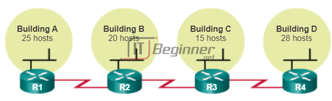
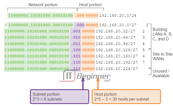
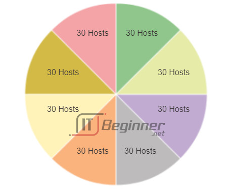
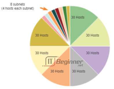
For example, the topology shown in Figure 1 requires seven subnets, one for each of the four LANs and one for each of the three WAN connections between routers. Using traditional subnetting with the given address of 192.168.20.0/24, 3 bits can be borrowed from the host portion in the last octet to meet the subnet requirement of seven subnets. As shown in Figure 2, borrowing 3 bits creates 8 subnets and leaves 5 host bits with 30 usable hosts per subnet. This scheme creates the needed subnets and meets the host requirement of the largest LAN.
Although this traditional subnetting meets the needs of the largest LAN and divides the address space into an adequate number of subnets, it results in significant waste of unused addresses.
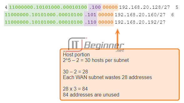
For example, only two addresses are needed in each subnet for the three WAN links. Because each subnet has 30 usable addresses, there are 28 unused addresses in each of these subnets. As shown in Figure 3, this results in 84 unused addresses (28×3).
Further, this limits future growth by reducing the total number of subnets available. This inefficient use of addresses is characteristic of traditional subnetting of classful networks.
Applying a traditional subnetting scheme to this scenario is not very efficient and is wasteful. In fact, this example is a good model for showing how subnetting a subnet can be used to maximize address utilization.
Subnetting a subnet, or using Variable Length Subnet Mask (VLSM), was designed to avoid wasting addresses.
[tabs type=”horizontal”]
[tabs_head]
[tab_title]Figure 1[/tab_title]
[tab_title]Figure 2[/tab_title]
[tab_title]Figure 3[/tab_title]
[/tabs_head]
[tab]
[/tab]
[tab]
[/tab]
[tab]
[/tab]
[/tabs]
9.1.5.2 Variable Length Subnet Masks (VLSM)
In all of the previous examples of subnetting, notice that the same subnet mask was applied for all the subnets. This means that each subnet has the same number of available host addresses.
As illustrated in Figure 1, traditional subnetting creates subnets of equal size. Each subnet in a traditional scheme uses the same subnet mask. As shown in Figure 2, VLSM allows a network space to be divided in unequal parts. With VLSM the subnet mask will vary depending on how many bits have been borrowed for a particular subnet, thus the “variable” part of the VLSM.
VLSM subnetting is similar to traditional subnetting in that bits are borrowed to create subnets. The formulas to calculate the number of hosts per subnet and the number of subnets created still apply. The difference is that subnetting is not a single pass activity. With VLSM, the network is first subnetted, and then the subnets are subnetted again. This process can be repeated multiple times to create subnets of various sizes.
[tabs type=”horizontal”]
[tabs_head]
[tab_title]Figure 1[/tab_title]
[tab_title]Figure 2[/tab_title]
[/tabs_head]
[tab]
[/tab]
[tab]
[/tab]
[/tabs]
9.1.5.3 Basic VLSM
To better understand the VLSM process, go back to the previous example.
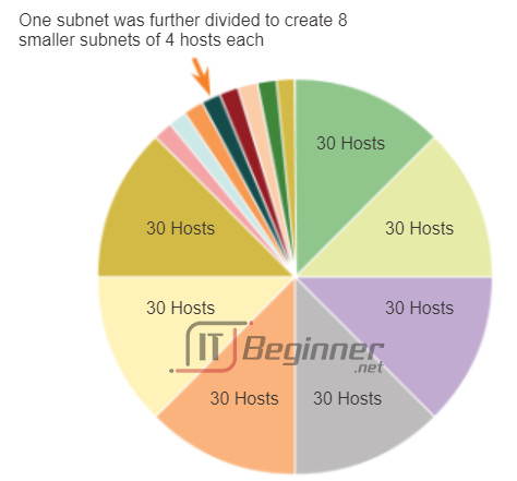
In the previous example, shown in Figure 1, the network 192.168.20.0/24 was subnetted into eight equal sized subnets; seven of the eight subnets were allocated. Four subnets were used for the LANs and three subnets for the WAN connections between the routers. Recall that the wasted address space was in the subnets used for the WAN connections, because those subnets required only two usable addresses: one for each router interface. To avoid this waste, VLSM can be used to create smaller subnets for the WAN connections.
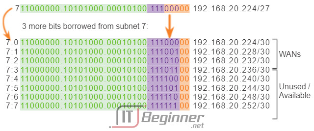
To create smaller subnets for the WAN links, one of the subnets will be divided. In Figure 2, the last subnet, 192.168.20.224/27, will be further subnetted.
Recall that when the number of needed host addresses is known, the formula 2^n-2 (where n equals the number of host bits remaining) can be used. To provide two usable addresses, 2 host bits must be left in the host portion.
2^2 – 2 = 2
Because there are 5 host bits in the 192.168.20.224/27 address space, 3 bits can be borrowed, leaving 2 bits in the host portion.
The calculations at this point are exactly the same as those used for traditional subnetting. The bits are borrowed and the subnet ranges are determined.
As shown in Figure 2, this VLSM subnetting scheme reduces the number addresses per subnet to a size appropriate for the WANs. Subnetting subnet 7 for WANs, allows subnets 4, 5, and 6 to be available for future networks, as well as several other subnets available for WANs.
[tabs type=”horizontal”]
[tabs_head]
[tab_title]Figure 1[/tab_title]
[tab_title]Figure 2[/tab_title]
[/tabs_head]
[tab]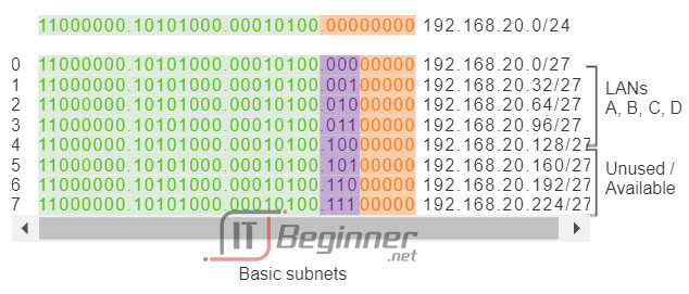 [/tab]
[tab]
[/tab]
[/tabs]
9.1.5.4 VLSM in Practice
Using the VLSM subnets, the LAN and WAN segments can be addressed without unnecessary waste.
The hosts in each of the LANs will be assigned a valid host address with the range for that subnet and /27 mask. Each of the four routers will have a LAN interface with a /27 subnet and a one or more serial interfaces with a /30 subnet.
Using a common addressing scheme, the first host IPv4 address for each subnet is assigned to the LAN interface of the router. The WAN interfaces of the routers are assigned the IP addresses and mask for the /30 subnets.
Figures 1 – 4 show the interface configuration for each of the routers.
Hosts on each subnet will have a host IPv4 address from the range of host addresses for that subnet and an appropriate mask. Hosts will use the address of the attached router LAN interface as the default gateway address.
- Building A Hosts (192.168.20.0/27) will use router 192.168.20.1 address as the default gateway address.
- Building B Hosts (192.168.20.32/27) will use router 192.168.20.33 address as the default gateway address.
- Building C Hosts (192.168.20.64/27) will use router 192.168.20.65 address as the default gateway address.
- Building D Hosts (192.168.20.96/27) will use router 192.168.20.97 address as the default gateway address.
[tabs type=”horizontal”]
[tabs_head]
[tab_title]Figures 1[/tab_title]
[tab_title]Figures 2[/tab_title]
[tab_title]Figures 3[/tab_title]
[tab_title]Figures 4[/tab_title]
[/tabs_head]
[tab]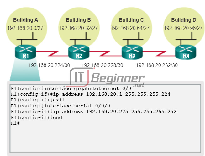 [/tab]
[tab]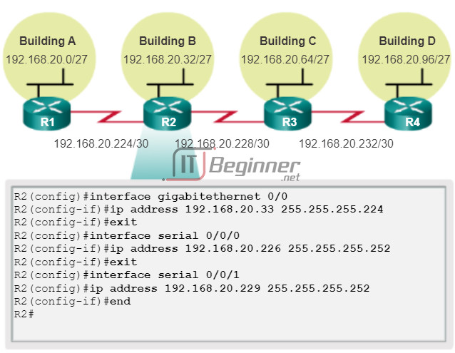 [/tab]
[tab]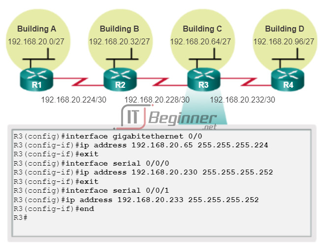 [/tab]
[tab]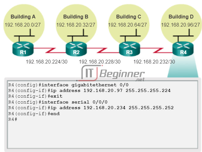 [/tab]
[/tabs]
9.1.5.5 VLSM Chart
Address planning can also be accomplished using a variety of tools. One method is to use a VLSM chart to identify which blocks of addresses are available for use and which ones are already assigned. This method helps to prevent assigning addresses that have already been allocated. Using the network from the previous example, the VLSM chart can be used to plan address assignment.
Examining the /27 Subnets
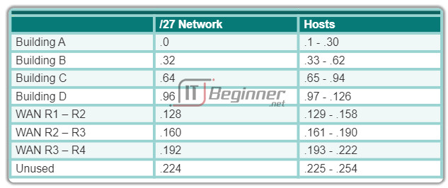
As shown in Figure 1, when using traditional subnetting the first seven address blocks were allocated for LANs and WANs. Recall that this scheme resulted in 8 subnets with 30 usable addresses each (/27). While this scheme worked for the LAN segments, there were many wasted addresses in the WAN segments.
When designing the addressing scheme on a new network, the address blocks can be assigned in a way that minimizes waste and keeps unused blocks of addresses contiguous.
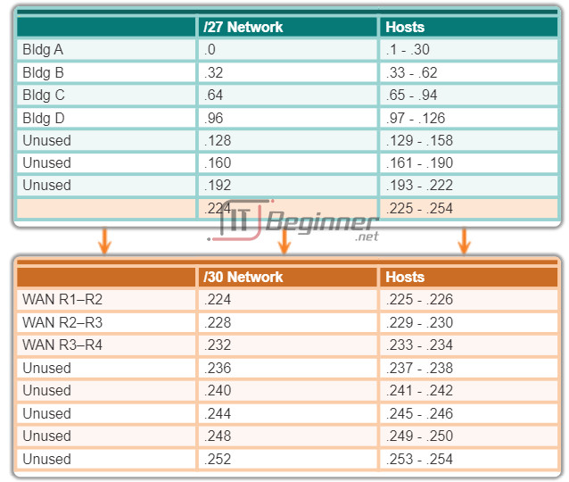
Assigning VLSM Address Blocks
As shown in Figure 2, in order to use the address space more efficiently, /30 subnets are created for WAN links. To keep the unused blocks of addresses together, the last /27 subnet was further subnetted to create the /30 subnets. The first 3 subnets were assigned to WAN links.
- .224 /30 host address range 225 to 226: WAN link between R1 and R2
- .228 /30 host address range 229 to 230: WAN link between R2 and R3
- .232 /30 host address range 233 to 234: WAN link between R3 and R4
- .236 /30 host address range 237 to 238: Available to be used
- .240 /30 host address range 241 to 242: Available to be used
- .244 /30 host address range 245 to 246: Available to be used
- .248 /30 host address range 249 to 250: Available to be used
- .252 /30 host address range 253 to 254: Available to be used
Designing the addressing scheme in this way leaves 3 unused /27 subnets and 5 unused /30 subnets.
[tabs type=”horizontal”]
[tabs_head]
[tab_title]Figure 1[/tab_title]
[tab_title]Figure 2[/tab_title]
[/tabs_head]
[tab]
[/tab]
[tab]
[/tab]
[/tabs]
9.1.5.6 Activity – Practicing VLSM
9.2 Addressing Schemes
9.2.1 Structured Design
9.2.1.1 Planning to Address the Network
As shown in the figure, the allocation of network layer address space within the corporate network needs to be well designed. Address assignment should not be random. There are three primary considerations when planning address allocation.
- Preventing Duplication of Addresses – Each host in an internetwork must have a unique address. Without the proper planning and documentation, an address could be assigned to more than one host, resulting in access issues for both hosts.
- Providing and Controlling Access – Some hosts, such as servers, provide resources to internal hosts as well as to external hosts. The Layer 3 address assigned to a server can be used to control access to that server. If, however, the address is randomly assigned and not well documented, controlling access is more difficult.
- Monitoring Security and Performance – Similarly, the security and performance of network hosts and the network as a whole must be monitored. As part of the monitoring process, network traffic is examined for addresses that are generating or receiving excessive packets. If there is proper planning and documentation of the network addressing, problematic network devices can be easily found.
Assigning Addresses within a Network
Within a network, there are different types of devices, including:
- End user clients
- Servers and peripherals
- Hosts that are accessible from the Internet
- Intermediary devices
- Gateway
When developing an IP addressing scheme, it is generally recommended to have a set pattern of how addresses are allocated to each type of device. This benefits administrators when adding and removing devices, filtering traffic based on IP, as well as simplifies documentation.
9.2.1.2 Assigning Addresses to Devices
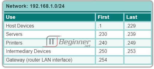
A network addressing plan might include using a different range of addresses within each subnet, for each type of device.
Addresses for Clients
Because of the challenges associated with static address management, end user devices often have addresses dynamically assigned, using Dynamic Host Configuration Protocol (DHCP). DHCP is generally the preferred method of assigning IP addresses to hosts on large networks because it reduces the burden on network support staff and virtually eliminates entry errors.
Another benefit of DHCP is that an address is not permanently assigned to a host but is only leased for a period of time. If we need to change the subnetting scheme of our network, we do not have to statically reassign individual host addresses. With DHCP, we only need to reconfigure the DHCP server with the new subnet information. After this has been done, the hosts only need to automatically renew their IP addresses.
Addresses for Servers and Peripherals
Any network resource, such as a server or a printer, should have a static IP address, as shown in the figure. The client hosts access these resources using the IP addresses of these devices. Therefore, predictable addresses for each these servers and peripherals are necessary.
Servers and peripherals are a concentration point for network traffic. There are many packets sent to and from the IPv4 addresses of these devices. When monitoring network traffic with a tool like Wireshark, a network administrator should be able to rapidly identify these devices. Using a consistent numbering system for these devices makes the identification easier.
Addresses for Hosts that are Accessible from Internet
In most internetworks, only a few devices are accessible by hosts outside of the corporation. For the most part, these devices are usually servers of some type. As with all devices in a network that provide network resources, the IP addresses for these devices should be static.
In the case of servers accessible by the Internet, each of these must have a public space address associated with it. Additionally, variations in the address of one of these devices will make this device inaccessible from the Internet. In many cases, these devices are on a network that is numbered using private addresses. This means that the router or firewall at the perimeter of the network must be configured to translate the internal address of the server into a public address. Because of this additional configuration in the perimeter intermediary device, it is even more important that these devices have a predictable address.
Addresses for Intermediary Devices
Intermediary devices are also a concentration point for network traffic. Almost all traffic within or between networks passes through some form of intermediary device. Therefore, these network devices provide an opportune location for network management, monitoring, and security.
Most intermediary devices are assigned Layer 3 addresses, either for the device management or for their operation. Devices, such as hubs, switches, and wireless access points do not require IPv4 addresses to operate as intermediary devices. However, if we must access these devices as hosts to configure, monitor, or troubleshoot network operation, they must have addresses assigned.
Because we must know how to communicate with intermediary devices, they should have predictable addresses. Therefore, their addresses are typically assigned manually. Additionally, the addresses of these devices should be in a different range within the network block than user device addresses.
Address for the Gateway (Routers and Firewalls)
Unlike the other intermediary devices mentioned, routers and firewall devices have an IP address assigned to each interface. Each interface is in a different network and serves as the gateway for the hosts in that network. Typically, the router interface uses either the lowest or highest address in the network. This assignment should be uniform across all networks in the corporation so that network personnel will always know the gateway of the network no matter which network they are working on.
Router and firewall interfaces are the concentration point for traffic entering and leaving the network. Because the hosts in each network use a router or firewall device interface as the gateway out of the network, many packets flow through these interfaces. Therefore, these devices can play a major role in network security by filtering packets based on source and/or destination IP addresses. Grouping the different types of devices into logical addressing groups makes the assignment and operation of this packet filtering more efficient.
9.2.1.3 Lab – Designing and Implementing a Subnetted IPv4 Addressing Scheme
In this lab, you will complete the following objectives:
- Part 1: Design a Network Subnetting Scheme
- Part 2: Configure the Devices
- Part 3: Test and Troubleshoot the Network
Lab – Designing and Implementing a Subnetted IPv4 Addressing Scheme
9.2.1.4 Lab – Designing and Implementing a VLSM Addressing Scheme
In this lab, you will complete the following objectives:
- Part 1: Examine Network Requirements
- Part 2: Design the VLSM Address Scheme
- Part 3: Cable and Configure the IPv4 Network
Lab – Designing and Implementing a VLSM Addressing Scheme ./.
9.2.1.5 Packet Tracer – Designing and Implementing a VLSM Addressing Scheme
In this activity, you are given a network address to develop a VLSM addressing scheme for the network shown in the included topology.
Packet Tracer – Designing and Implementing a VLSM Addressing Scheme Instructions ./.
Packet Tracer – Designing and Implementing a VLSM Addressing Scheme PKA ./.
9.3 Design Considerations for IPv6
9.3.1 Subnetting an IPv6 Network
9.3.1.1 Subnetting Using the Subnet ID
IPv6 subnetting requires a different approach than IPv4 subnetting. The primary reason is that with IPv6 there are so many addresses, that the reason for subnetting is completely different. An IPv6 address space is not subnetted to conserve addresses; rather, it is subnetted to support hierarchical, logical design of the network. While IPv4 subnetting is about managing address scarcity, IPv6 subnetting is about building an addressing hierarchy based on the number of routers and the networks they support.
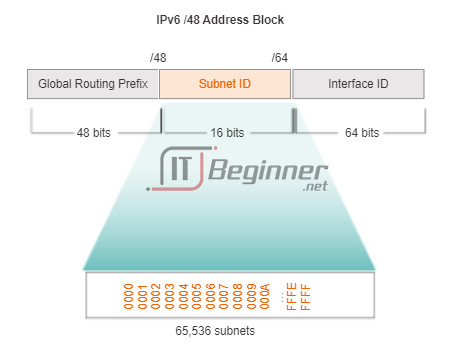
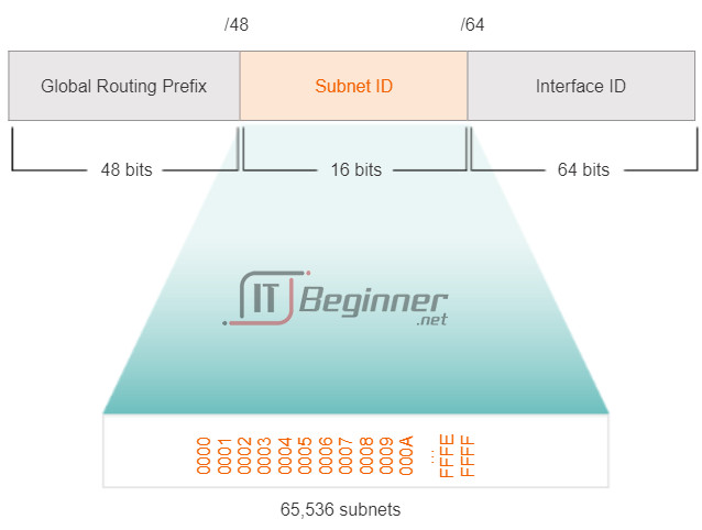
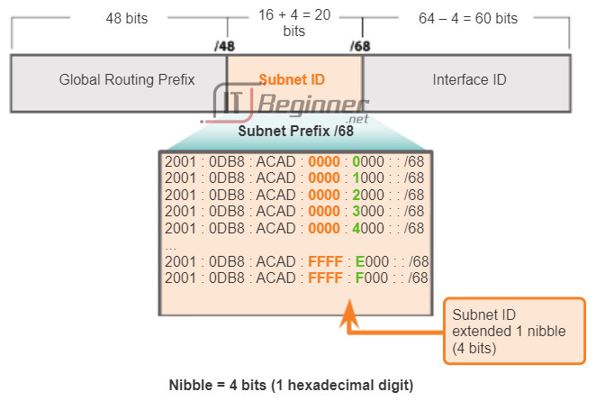
Recall that an IPv6 address block with a /48 prefix has 16 bits for subnet ID, as shown in Figure 1. Subnetting using the 16 bit subnet ID yields a possible 65,536 /64 subnets and does not require borrowing any bits from the interface ID, or host portion of the address. Each IPv6 /64 subnet contains roughly eighteen quintillion addresses, obviously more than will ever be needed in one IP network segment.
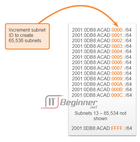
Subnets created from the subnet ID are easy to represent because there is no conversion to binary required. To determine the next available subnet, just count up in hexadecimal. As shown in Figure 2, this means counting by hexadecimal in the subnet ID portion.
The global routing prefix is the same for all subnets. Only the subnet ID quartet is incremented for each subnet.
[tabs type=”horizontal”]
[tabs_head]
[tab_title]Figure 1[/tab_title]
[tab_title]Figure 2[/tab_title]
[/tabs_head]
[tab]
[/tab]
[tab]
[/tab]
[/tabs]
9.3.1.2 IPv6 Subnet Allocation
With over 65,000 subnets to choose from, the task of the network administrator becomes one of designing a logical scheme to address the network.
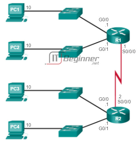
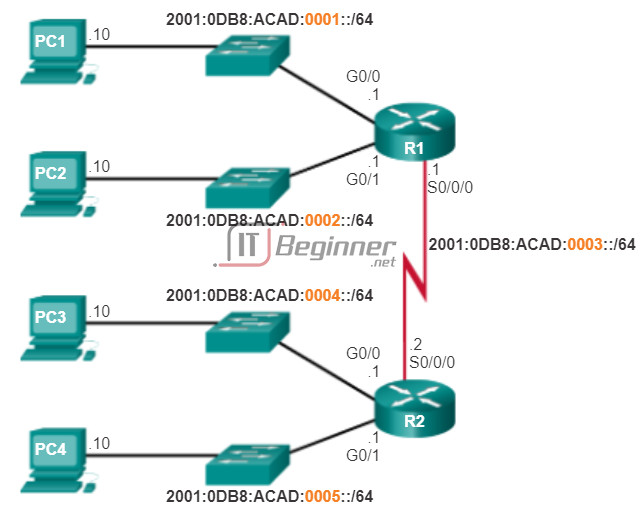
As shown in Figure 1, the example topology will require subnets for each LAN as well as for the WAN link between R1 and R2. Unlike the example for IPv4, with IPv6 the WAN link subnet will not be subnetted further. Although this may “waste” addresses, that is not a concern when using IPv6.
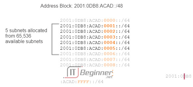
As shown in Figure 2, the allocation of 5 IPv6 subnets, with the subnet ID field 0001 through 0005 will be used for this example. Each /64 subnet will provide more addresses than will ever be needed.
As shown in Figure 3, each LAN segment and the WAN link is assigned a /64 subnet.
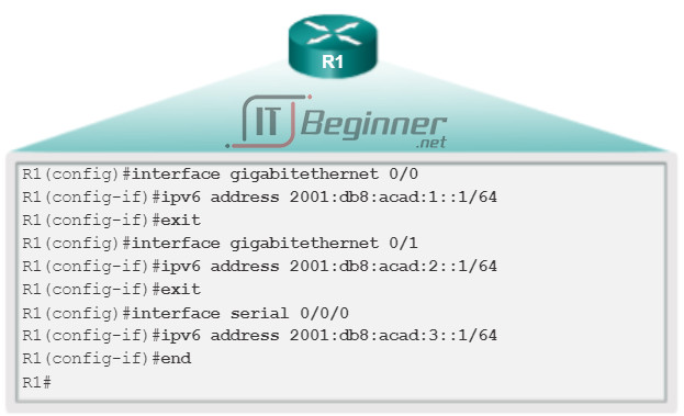
Similar to configuring IPv4, Figure 4 shows that each of the router interfaces has been configured to be on a different IPv6 subnet.
[tabs type=”horizontal”]
[tabs_head]
[tab_title]Figure 1[/tab_title]
[tab_title]Figure 2[/tab_title]
[tab_title]Figure 3[/tab_title]
[tab_title]Figure 4[/tab_title]
[/tabs_head]
[tab]
[/tab]
[tab]
[/tab]
[tab]
[/tab]
[tab]
[/tab]
[/tabs]
9.3.1.3 Subnetting into the Interface ID
Similar to borrowing bits from the host portion of an IPv4 address, with IPv6 bits can be borrowed from the interface ID to create additional IPv6 subnets. This is typically done for security reasons to create fewer hosts per subnet and not necessarily to create additional subnets.
When extending the subnet ID by borrowing bits from the interface ID, the best practice is to subnet on a nibble boundary. A nibble is 4 bits or one hexadecimal digit. As shown in the figure, the /64 subnet prefix is extended 4 bits or 1 nibble to /68. Doing this reduces the size of the interface ID by 4 bits, from 64 to 60 bits.
Subnetting on nibble boundaries means only using nibble aligned subnet masks. Starting at /64, the nibble aligned subnet masks are /68, /72, /76, /80, etc.
Subnetting on a nibble boundary creates subnets by using the additional hexadecimal value. In the example, the new subnet ID consists of the 5 hexadecimal values, ranging from 00000 through FFFFF.
It is possible to subnet within a nibble boundary, within a hexadecimal digit, but it is not recommended or even necessary. Subnetting within a nibble takes away the advantage easily determining the prefix from the interface ID. For example, if a /66 prefix length is used, the first two bits would be part of the subnet ID and the second two bits would be part of the interface ID.
9.3.1.4 Packet Tracer – Implementing a Subnetted IPv6 Addressing Scheme
Your network administrator wants you to assign five /64 IPv6 subnets to the network shown in the topology. Your job is to determine the IPv6 subnets, assign IPv6 addresses to the routers, and set the PCs to automatically receive IPv6 addressing. Your final step is to verify connectivity between IPv6 hosts.
Packet Tracer – Implementing a Subnetted IPv6 Addressing Scheme Instructions ./.
Packet Tracer – Implementing a Subnetted IPv6 Addressing Scheme – PKA ./.
9.4 Summary
9.4.1 Summary
9.4.1.1 Activity – Can you call me now?
Note: This activity may be completed individually or in small/large groups using Packet Tracer software.
You are setting up a dedicated, computer addressing scheme for patient rooms in a hospital. The switch will be centrally located in the nurses’ station, as each of the five rooms will be wired so that patients can just connect to a RJ-45 port built into the wall of their room. Devise a physical and logical topology for only one of the six floors using the following addressing scheme requirements:
- There are six floors with five patient rooms on each floor for a total of thirty connections. Each room needs a network connection.
- Subnetting must be incorporated into your scheme.
- Use one router, one switch, and five host stations for addressing purposes.
- Validate that all PCs can connect to the hospital’s in-house services.
Keep a copy of your scheme to share later with the class or learning community. Be prepared to explain how subnetting, unicasts, multicasts, and broadcasts would be incorporated, and where your addressing scheme could be used.
Class Activity – Can you call me now? Instructions ./.
Careful planning is required to make best use of an IP addressing scheme.
Plan for…
- Size
- Location
- Use
- Access requirements
9.4.1.2 Packet Tracer – Skills Integration Challenge
As a network technician familiar with IPv4 and IPv6 addressing implementations, you are now ready to take an existing network infrastructure and apply your knowledge and skills to finalize the configuration. The network administrator has already configured some commands on the routers. Do not to erase or modify those configurations. Your task is to complete the IPv4 and IPv6 addressing scheme, implement IPv4 and IPv6 addressing, and verify connectivity.
Packet Tracer – Skills Integration Challenge Instructions ./.
Packet Tracer – Skills Integration Challenge – PKA ./.
9.4.1.3 Summary
As shown in the figure, the process of segmenting a network, by dividing it into to multiple smaller network spaces, is called subnetting.
Every network address has a valid range of host addresses. All devices attached to the same network will have an IPv4 host address for that network and a common subnet mask or network prefix. Traffic can be forwarded between hosts directly if they are on the same subnet. Traffic cannot be forwarded between subnets without the use of a router. To determine if traffic is local or remote, the router uses the subnet mask. The prefix and the subnet mask are different ways of representing the same thing – the network portion of an address.
IPv4 subnets are created by using one or more of the host bits as network bits. Two very important factors that will lead to the determination of the IP address block with the subnet mask, are the number of subnets required and the maximum number of hosts needed per subnet. There is an inverse relationship between the number of subnets and the number of hosts. The more bits borrowed to create subnets the fewer host bits are available; therefore fewer hosts per subnet.
The formula 2^n (where n is the number of host bits remaining) is used to calculate how many addresses will be available on each subnet. However, the network address and broadcast address within a range are not useable; therefore, to calculate the useable number of addresses the calculation 2^n-2 is required.
Subnetting a subnet, or using Variable Length Subnet Mask (VLSM) was designed to avoid wasting addresses.
IPv6 subnetting requires a different approach than IPv4 subnetting. An IPv6 address space is not subnetted to conserve addresses; rather it is subnetted to support hierarchical, logical design of the network. So, while IPv4 subnetting is about managing address scarcity, IPv6 subnetting is about building an addressing hierarchy based on the number of routers and the networks they support.
Careful planning is required to make best use of the available address space. Size, location, use, and access requirements are all considerations in the address planning process.
After it is implemented, an IP network needs to be tested to verify its connectivity and operational performance.