Introduction to Networks Instructor Materials – Chapter 8: IP Addressing
8.0 IP Addressing
8.0.1 Introduction
8.0.1.1 Introduction
Addressing is a key function of network layer protocols that enables data communication between hosts, regardless of whether the hosts are on the same network or on different networks. Both Internet Protocol version 4 (IPv4) and Internet Protocol version 6 (IPv6) provide hierarchical addressing for packets that carry data.
Designing, implementing and managing an effective IP addressing plan ensures that networks can operate effectively and efficiently.
This chapter examines in detail the structure of IP addresses and their application to the construction and testing of IP networks and subnetworks.
Upon completion of this chapter you will be able to:
- Describe the structure of an IPv4 address.
- Describe the purpose of the subnet mask.
- Compare the characteristics and uses of the unicast, broadcast, and multicast IPv4 addresses.
- Compare the use of public address space and private address space.
- Explain the need for IPv6 addressing.
- Describe the representation of an IPv6 address.
- Describe types of IPv6 network addresses.
- Configure global unicast addresses.
- Describe multicast addresses.
- Describe the role of ICMP in an IP network. (include IPv4 and IPv6.)
- Use ping and traceroute utilities to test network connectivity.
8.0.1.2 Activity –The Internet of Everything (IoE)
8.1 IPv4 Network Addresses
8.1.1 IPv4 Address Structure
8.1.1.1 Binary Notation
To understand the operation of devices on a network, we need to look at addresses and other data the way devices do – in binary notation. Binary notation is a representation of information using only ones and zeros. Computers communicate using binary data. Binary data can be used to represent many different forms of data. For example, when typing letters on a keyboard, those letters appear on screen in a form that you can read and understand; however, the computer translates each letter to a series of binary digits for storage and transport. To translate those letters, the computer uses American Standard Code for Information Interchange (ASCII).
Using ASCII, the letter “A” is represented in bit form as: 01000001, while the lowercase letter “a” is represented in bit form as 01100001. Use the ASCII translator in Figure 1 to convert ASCII characters to binary.
While it is not generally necessary for people to concern themselves with binary conversion of letters, it is necessary to understand the use of binary for IP addressing. Each device on a network must be uniquely identified using a binary address. In IPv4 networks, this address is represented using a string of 32 bits (1s and 0s). At the network layer, the packets then include this unique identification information for both the source and destination systems. Therefore, in an IPv4 network, each packet includes a 32-bit source address and a 32-bit destination address in the Layer 3 header.
For most individuals, a string of 32 bits is difficult to interpret and even more difficult to remember. Therefore, we represent IPv4 addresses using dotted decimal format instead of binary. This means that we look at each byte (octet) as a decimal number in the range of 0 to 255. To understand how this works we need to have some skill in binary to decimal conversion.
Positional Notation
Learning to convert binary to decimal requires an understanding of the mathematical basis of a numbering system called positional notation. Positional notation means that a digit represents different values depending on the position the digit occupies. In a positional notation system, the number base is called the radix. In the base ten system, the radix is 10. In the binary system we use a radix of 2. The term radix and base can be used interchangeably. More specifically, the value that a digit represents is that value multiplied by the power of the base, or radix, represented by the position the digit occupies. Some examples will help to clarify how this system works.
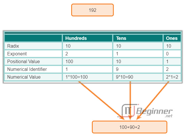
For the decimal number 192, the value that the 1 represents is 1*10^2 (1 times 10 to the power of 2). The 1 is in what we commonly refer to as the “100s” position. Positional notation refers to this position as the base^2 position because the base, or radix, is 10 and the power is 2. The 9 represents 9*10^1 (9 times 10 to the power of 1). Positional notation for the decimal number 192 is shown in Figure 2.
Using positional notation in the base 10 number system, 192 represents:
192 = (1 * 10^2) + (9 * 10^1) + (2 * 10^0)
or
192 = (1 * 100) + (9 * 10) + (2 * 1)
[tabs type=”horizontal”]
[tabs_head]
[tab_title]Figure 1[/tab_title]
[tab_title]Figure 2[/tab_title]
[/tabs_head]
[tab]ASCII Digital Translator[/tab]
[tab]
[/tab]
[/tabs]
8.1.1.2 Binary Number System
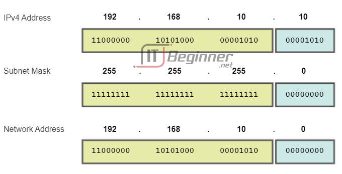
In IPv4, addresses are 32-bit binary numbers. However, for ease of use by people, binary patterns representing IPv4 addresses are expressed as dotted decimals. This is first accomplished by separating each byte (8 bits) of the 32-bit binary pattern, called an octet, with a dot. It is called an octet because each decimal number represents one byte or 8 bits.
The binary address:
11000000 10101000 00001010 00001010
is expressed in dotted decimal as:
192.168.10.10
In Figure 1, select each button to see how the 32-bit binary address is represented in dotted decimal octets.
But how are the actual decimal equivalents determined?
Binary Numbering System
In the binary numbering system, the radix is 2. Therefore, each position represents increasing powers of 2. In 8-bit binary numbers, the positions represent these quantities:
2^7 2^6 2^5 2^4 2^3 2^2 2^1 2^0
128 64 32 16 8 4 2 1
The base 2 numbering system only has two digits: 0 and 1.
When we interpret a byte as a decimal number, we have the quantity that position represents if the digit is a 1 and we do not have that quantity if the digit is a 0, as shown in Figure 1.
Figure 2 illustrates the representation of the decimal number 192 in binary. A 1 in a certain position means we add that value to the total. A 0 means we do not add that value. The binary number 11000000 has a 1 in the 2^7 position (decimal value 128) and a 1 in the 2^6 position (decimal value 64). The remaining bits are all 0 so we do not add the corresponding decimal values. The result of adding 128+64 is 192, the decimal equivalent of 11000000.
Here are two more examples:
Example 1: An octet containing all 1s: 11111111
A 1 in each position means that we add the value for that position to the total. All 1s means that the values of every position are included in the total, therefore, the value of all 1s in an octet is 255.
128 + 64 + 32 + 16 + 8 + 4 + 2 + 1 = 255
Example 2: An octet containing all 0s: 00000000
A 0 in each position indicates that the value for that position is not included in the total. A 0 in every position yields a total of 0.
0 + 0 + 0 + 0 + 0 + 0 + 0 + 0 = 0
A different combination of ones and zeros will yield a different decimal value.
[tabs type=”horizontal”]
[tabs_head]
[tab_title]Figure 1[/tab_title]
[tab_title]Figure 2[/tab_title]
[/tabs_head]
[tab] [/tab]
[tab]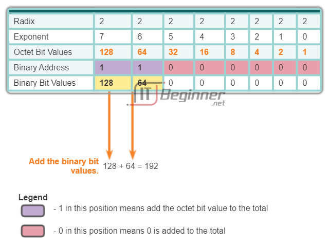 [/tab]
[/tabs]
8.1.1.3 Converting a Binary Address to Decimal
Each octet is made up of 8 bits and each bit has a value, either 0 or 1. The four groups of 8 bits have the same set of valid values in the range of 0 to 255 inclusive. The value of each bit placement, from right to left is 1, 2, 4, 8, 16, 32, 64, and 128.
Determine the value of the octet by adding the values of positions wherever there is a binary 1 present.
- If there is a 0 in a position, do not add the value.
- If all 8 bits are 0s, 00000000, the value of the octet is 0.
- If all 8 bits are 1s, 11111111, the value of the octet is 255 (128+64+32+16+8+4+2+1)
- If the 8 bits are mixed, the values are added together. For example, the octet 00100111 has a value of 39 (32+4+2+1).
So the value of each of the four octets can range from 0 to a maximum of 255.
Using the 32-bit IPv4 address, 11000000101010000000101000001010, convert the binary representation to dotted decimal using the following steps:
Step 1. Divide the 32 bits into 4 octets.
Step 2. Convert each octet to decimal.
Step 3. Add a “dot” between each decimal.
Click Play in the figure to see how a binary address is converted to dotted decimal.
8.1.1.4 Activity – Binary to Decimal Conversions
8.1.1.5 Converting from Decimal to Binary
In addition to being able to convert binary to decimal, it is also necessary to understand how to convert decimal to binary.
Because we represent IPv4 addresses using dotted decimal format, it is only necessary that we examine the process of converting 8-bit binary to the decimal values of 0 to 255 for each octet in an IPv4 address.
To begin the conversion process, we start by determining if the decimal number is equal to or greater than our largest decimal value represented by the most-significant bit. In the highest position, we determine if the octet number is equal to or greater than 128. If the octet number is smaller than 128, we place a 0 in the bit position for decimal value 128 and move to the bit position for decimal value 64.
If the octet number in the bit position for decimal value 128 is larger than or equal to 128, we place a 1 in the bit position for decimal value 128 and subtract 128 from the octet number being converted. We then compare the remainder of this operation to the next smaller value, 64. We continue this process for all the remaining bit positions.
Click through Figures 1-6 to see the process of converting 168 to the binary equivalent of 10101000.
[tabs type=”horizontal”]
[tabs_head]
[tab_title]Figures 1[/tab_title]
[tab_title]Figures 2[/tab_title]
[tab_title]Figures 3[/tab_title]
[tab_title]Figures 4[/tab_title]
[tab_title]Figures 5[/tab_title]
[tab_title]Figures 6[/tab_title]
[/tabs_head]
[tab]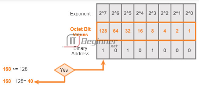 [/tab]
[tab]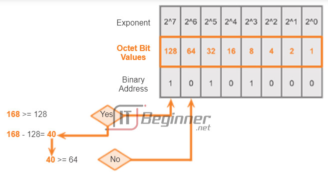 [/tab]
[tab]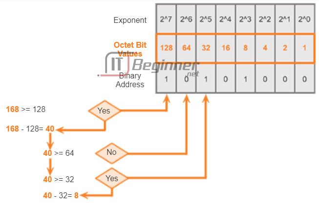 [/tab]
[tab]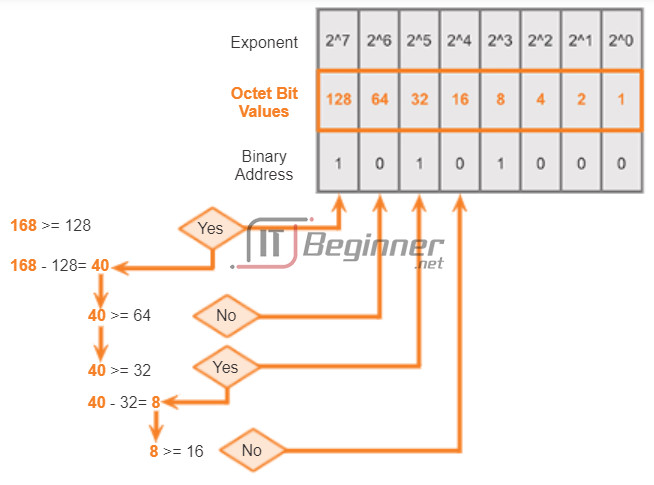 [/tab]
[tab]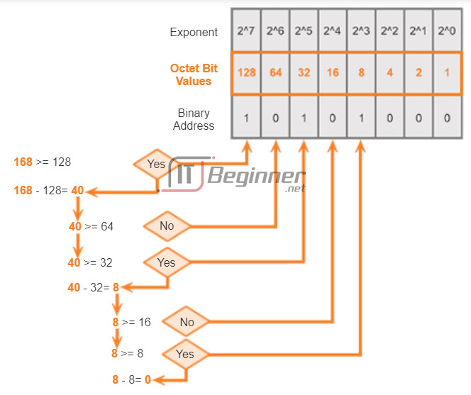 [/tab]
[tab]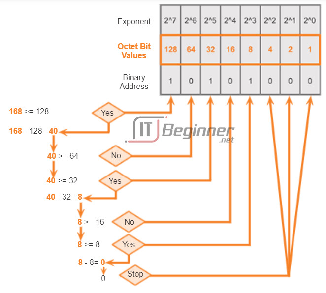 [/tab]
[/tabs]
8.1.1.6 Converting from Decimal to Binary (Cont.)
Follow the conversion steps in the figures to see how an IP address is converted to binary.
Figure 1: Convert 192 to binary.
Figure 2: Convert 168 to binary.
Figure 3: Convert 10 to binary.
Figure 4: Convert 10 to binary.
Figure 5: Combine the converted octets beginning with the first octet.
[tabs type=”horizontal”]
[tabs_head]
[tab_title]Figure 1[/tab_title]
[tab_title]Figure 2[/tab_title]
[tab_title]Figure 3[/tab_title]
[tab_title]Figure 4[/tab_title]
[tab_title]Figure 5[/tab_title]
[/tabs_head]
[tab]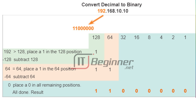 [/tab]
[tab]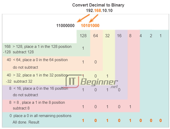 [/tab]
[tab]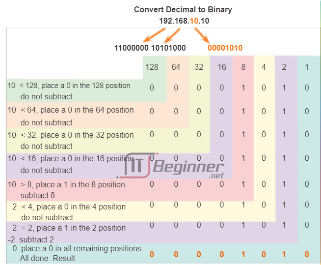 [/tab]
[tab]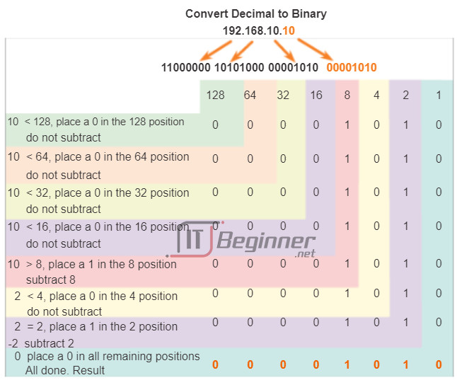 [/tab]
[tab]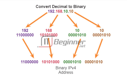 [/tab]
[/tabs]
8.1.1.7 Activity – Decimal to Binary Conversion Activity
8.1.1.8 Activity – Binary Game
8.1.2 IPv4 Subnet Mask
8.1.2.1 Network Portion and Host Portion of an IPv4 Address
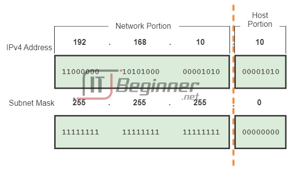
Understanding binary notation is important when determining if two hosts are in the same network. Recall that an IP address is a hierarchical address that is made up of two parts: a network portion and a host portion. But when determining the network portion versus the host portion, it is necessary to look, not at the decimal value, but at the 32-bit stream. Within the 32-bit stream, a portion of the bits makes up the network and a portion of the bits makes up the host.
The bits within the network portion of the address must be identical for all devices that reside in the same network. The bits within the host portion of the address must be unique to identify a specific host within a network. Regardless of whether the decimal numbers between two IPv4 addresses match up, if two hosts have the same bit-pattern in the specified network portion of the 32-bit stream, those two hosts will reside in the same network.
But how do hosts know which portion of the 32-bits is network and which is host? That is the job of the subnet mask.
When an IP host is configured, a subnet mask is assigned along with an IP address. Like the IP address, the subnet mask is 32 bits long. The subnet mask signifies which part of the IP address is network and which part is host.
The subnet mask is compared to the IP address from left to right, bit for bit. The 1s in the subnet mask represent the network portion; the 0s represent the host portion. As shown in Figure 1, the subnet mask is created by placing a binary 1 in each bit position that represents the network portion and placing a binary 0 in each bit position that represents the host portion. Note that the subnet mask does not actually contain the network or host portion of an IPv4 address, it just tells the computer where to look for these portions in a given IPv4 address.
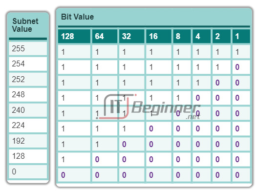
Similar to IPv4 addresses, the subnet mask is represented in dotted decimal format for ease of use. The subnet mask is configured on a host device, in conjunction with the IPv4 address, and is required so the host can determine which network it belongs to. Figure 2 displays the valid subnet masks for an IPv4 octet.
[tabs type=”horizontal”]
[tabs_head]
[tab_title]Figure 1[/tab_title]
[tab_title]Figure 2[/tab_title]
[/tabs_head]
[tab]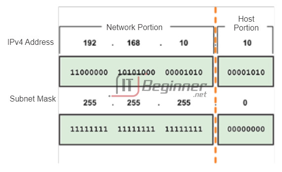 [/tab]
[tab]
[/tab]
[/tabs]
8.1.2.2 Examining the Prefix Length
The prefix length is another way of expressing the subnet mask. The prefix length is the number of bits set to 1 in the subnet mask. It is written in “slash notation”, a “/” followed by the number of bits set to 1. For example, if the subnet mask is 255.255.255.0, there are 24 bits set to 1 in the binary version of the subnet mask, so the prefix length is 24 bits or /24. The prefix and the subnet mask are different ways of representing the same thing – the network portion of an address.
Networks are not always assigned a /24 prefix. Depending on the number of hosts on the network, the prefix assigned may be different. Having a different prefix number changes the host range and broadcast address for each network.
The figures illustrate different prefixes using the same 10.1.1.0 address. Figure 1 illustrates /24 to /26 prefixes. Figure 2 illustrates /27 to /28 prefixes.
Notice that the network address could remain the same, but the host range and the broadcast address are different for the different prefix lengths. In the figures, you can see that the number of hosts that can be addressed on the network also changes.
[tabs type=”horizontal”]
[tabs_head]
[tab_title]Figure 1[/tab_title]
[tab_title]Figure 2[/tab_title]
[/tabs_head]
[tab]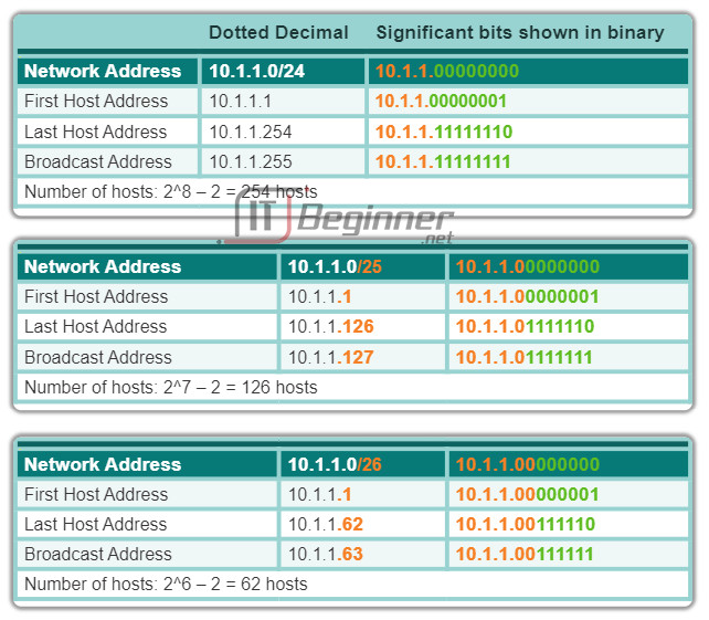 [/tab]
[tab]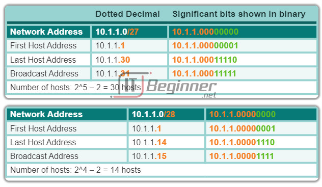 [/tab]
[/tabs]
8.1.2.3 IPv4 Network, Host and Broadcast Addresses
There are three types of addresses within the address range of each IPv4 network:
- Network address
- Host addresses
- Broadcast address
Network Address
The network address is a standard way to refer to a network. The subnet mask or the prefix length might also be used when referring to network address. For example, the network shown in Figure 1 could be referred to as the 10.1.1.0 network, the 10.1.1.0 255.255.255.0 network or the 10.1.1.0/24 network. All hosts in the 10.1.1.0/24 network will have the same network portion bits.
As shown in Figure 2, within the IPv4 address range of a network, the first address is reserved for the network address. This address has a 0 for each host bit in the host portion of the address. All hosts within the network share the same network address.
Host Address
Every end device requires a unique address to communicate on the network. In IPv4 addresses, the values between the network address and the broadcast address can be assigned to end devices in a network. As shown in Figure 3, this address has any combination of 0 and 1 bits in the host portion of the address but cannot contain all 0 bits or all 1 bits.
Broadcast Address
The IPv4 broadcast address is a special address for each network that allows communication to all the hosts in that network. To send data to all hosts in a network at once, a host can send a single packet that is addressed to the broadcast address of the network, and each host in the network that receives this packet will process its contents.
The broadcast address uses the highest address in the network range. This is the address in which the bits in the host portion are all 1s. All 1s in an octet in binary form, is equal to the number 255 in decimal form. Therefore, as shown in Figure 4, for the network 10.1.1.0/24, in which the last octet is used for the host portion, the broadcast address would be 10.1.1.255. Note that the host portion will not always be an entire octet. This address is also referred to as the directed broadcast.
[tabs type=”horizontal”]
[tabs_head]
[tab_title]Figure 1[/tab_title]
[tab_title]Figure 2[/tab_title]
[tab_title]Figure 3[/tab_title]
[tab_title]Figure 4[/tab_title]
[/tabs_head]
[tab]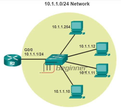 [/tab]
[tab]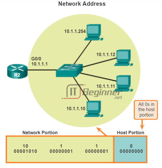 [/tab]
[tab]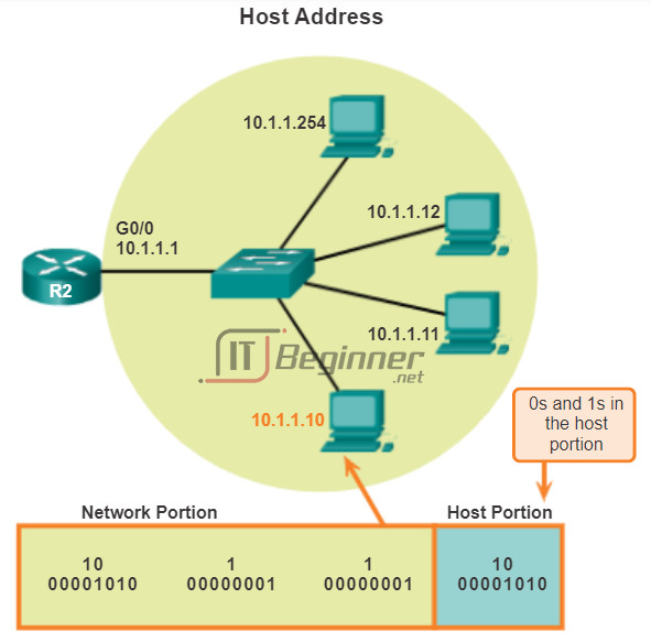 [/tab]
[tab]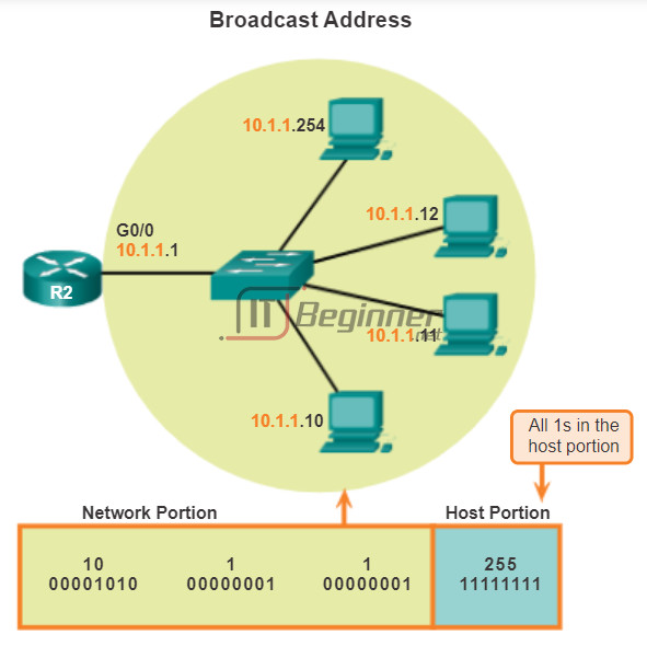 [/tab]
[/tabs]
8.1.2.4 First Host and Last Host Addresses
To ensure that all hosts within a network are assigned a unique IP address within that network range, it is important to identify the first host address and the last host address. Hosts within a network can be assigned IP addresses within this range.
First Host Address
As seen in Figure 1, the host portion of the first host address will contain all 0 bits with a 1 bit for the lowest order or right-most bit. This address is always one greater than the network address. In this example the first host address on the 10.1.1.0/24 network is 10.1.1.1. It is common in many addressing schemes to use the first host address for the router or default gateway address.
Last Host Address
The host portion of the last host address will contain all 1 bits with a 0 bit for the lowest order or right-most bit. This address is always one less than the broadcast address. As seen in Figure 2, the last host address on the 10.1.1.0/24 network is 10.1.1.254.
[tabs type=”horizontal”]
[tabs_head]
[tab_title]First Host Address[/tab_title]
[tab_title]Last Host Address[/tab_title]
[/tabs_head]
[tab]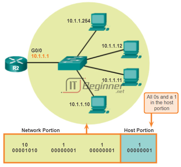 [/tab]
[tab]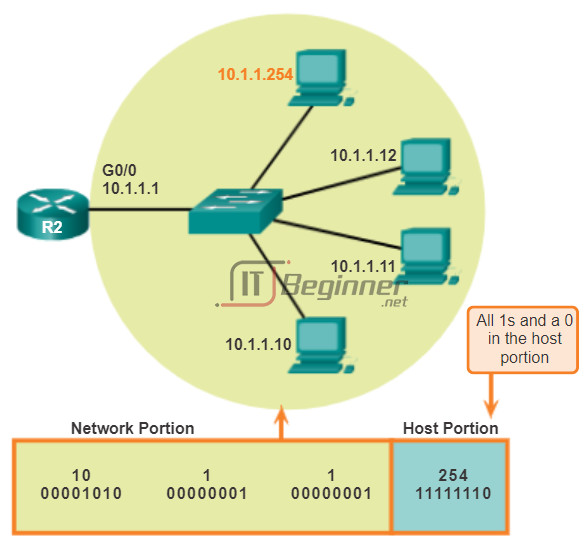 [/tab]
[/tabs]
8.1.2.5 Bitwise AND Operation
When an IPv4 address is assigned to a device, that device uses the subnet mask to determine what network address the device belongs to. The network address is the address that represents all the devices on the same network.
When sending network data, the device uses this information to determine whether it can send packets locally, or if it must send the packets to a default gateway for remote delivery. When a host sends a packet, it compares the network portion of its own IP address to the network portion of the destination IP address, based on subnet masks. If the network bits match, both the source and destination host are on the same network and the packet can be delivered locally. If they do not match, the sending host forwards the packet to the default gateway to be sent on to the other network.
The AND Operation
ANDing is one of three basic binary operations used in digital logic. The other two are OR and NOT. While all three are used in data networks, AND is used in determining the network address. Therefore, our discussion here will be limited to logical AND. Logical AND is the comparison of two bits that yields the following results:
1 AND 1 = 1 (Figure 1)
0 AND 1 = 0 (Figure 2)
0 AND 0 = 0 (Figure 3)
1 AND 0 = 0 (Figure 4)
The IPv4 host address is logically ANDed, bit by bit, with its subnet mask to determine the network address to which the host is associated. When this bitwise ANDing between the address and the subnet mask is performed, the result yields the network address.
[tabs type=”horizontal”]
[tabs_head]
[tab_title]1 AND 1 = 1[/tab_title]
[tab_title]0 AND 1 = 0[/tab_title]
[tab_title]0 AND 0 = 0[/tab_title]
[tab_title]1 AND 0 = 0[/tab_title]
[/tabs_head]
[tab]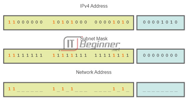 [/tab]
[tab]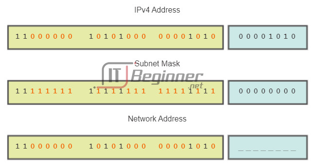 [/tab]
[tab]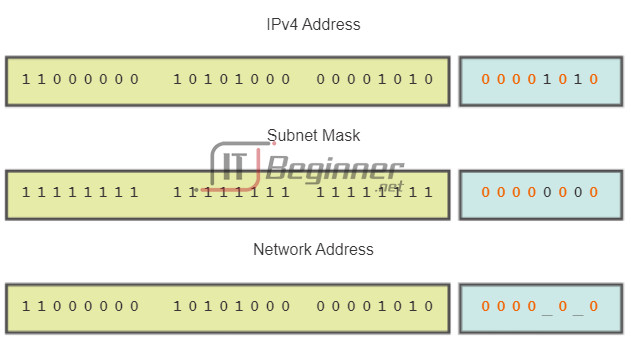 [/tab]
[tab]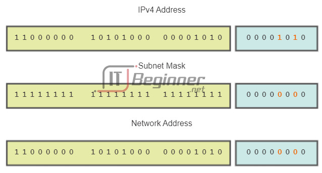 [/tab]
[/tabs]
8.1.2.6 Importance of ANDing
Any address bit ANDed with a 1 bit value from the subnet mask will yield the original bit value from the address. So, a 0 (from the IPv4 address) AND 1 (from the subnet mask) is 0. 1 (from the IPv4 address) AND 1(from the subnet mask) is 1. Consequently, anything ANDed with a 0 yields a 0. These properties of ANDing are used with the subnet mask to “mask” the host bits of an IPv4 address. Each bit of the address is ANDed with the corresponding bit of the subnet mask.
Because all the bits of the subnet mask that represent host bits are 0s, the host portion of the resulting network address becomes all 0s. Recall that an IPv4 address with all 0s in the host portion represents the network address.
Likewise, all the bits of the subnet mask that indicate network portion are 1s. When each of these 1s is ANDed with the corresponding bit of the address, the resulting bits are identical to the original address bits.
As shown in the figure, the 1 bits in the subnet mask will result in the network portion of the network address having the same bits as the network portion of the host. The host portion of the network address will result in all 0s.
For a given IP address and its subnet, ANDing can be used to determine what subnetwork the address belongs to, as well as what other addresses belong to the same subnet. Remember that if two addresses are in the same network or subnetwork, they are considered to be local to each other and can therefore communicate directly with each other. Addresses that are not in the same network or subnetwork are considered to be remote to each other and must therefore have a Layer 3 device (like a router or Layer 3 switch) between them to communicate.
In network verification/troubleshooting, we often need to determine two hosts are on the same local network. We need to make this determination from the perspective of the network devices. Due to improper configuration, a host may see itself on a network that was not the intended one. This can create an operation that seems erratic unless diagnosed by examining the ANDing processes used by the host.
8.1.2.7 Lab – Using the Windows Calculator with Network Addresses
In this lab, you will complete the following objectives:
- Part 1: Access the Windows Calculator
- Part 2: Convert between Numbering Systems
- Part 3: Convert Host IPv4 Addresses and Subnet Masks into Binary
- Part 4: Determine the Number of Hosts in a Network Using Powers of 2
- Part 5: Convert MAC Addresses and IPv6 Addresses to Binary
Lab – Using the Windows Calculator with Network Addresses ./.
8.1.2.8 Lab – Converting IPv4 Addresses to Binary
In this lab, you will complete the following objectives:
- Part 1: Convert IPv4 Addresses from Dotted Decimal to Binary
- Part 2: Use Bitwise ANDing Operation to Determine Network Addresses
- Part 3: Apply Network Address Calculations
Lab – Converting IPv4 Addresses to Binary ./.
8.1.2.9 Activity – ANDing to Determine the Network Address
8.1.3 IPv4 Unicast, Broadcast, and Multicast
8.1.3.1 Assigning a Static IPv4 Address to a Host
Addresses for User Devices
In most data networks, the largest population of hosts includes the end devices such as PCs, tablets, smartphones, printers, and IP phones. Because this represents the largest number of devices within a network, the largest number of addresses should be allocated to these hosts. These hosts are assigned IP addresses from the range of available addresses in the network. These IP addresses can be assigned either statically or dynamically.
Static Assignment
With a static assignment, the network administrator must manually configure the network information for a host. Figure 1 shows the window for the network adapter properties. To configure a static IPv4 address, choose IPv4 on the network adapter screen, then key in the static address, subnet mask, and default gateway. Figure 2 shows the minimum static configuration: the host IP address, subnet mask, and default gateway.
There are several advantages to static addressing. For instance, they are useful for printers, servers, and other networking devices that do not change location often and need to be accessible to clients on the network based on a fixed IP address. If hosts normally access a server at a particular IP address, it would cause problems if that address changed. Additionally, static assignment of addressing information can provide increased control of network resources. For example, it is possible to create access filters based on traffic to and from a specific IP address. However, static addressing can be time-consuming to enter on each host.
When using static IP addressing, it is necessary to maintain an accurate list of the IP address assigned to each device. These are permanent addresses and are not normally reused.
[tabs type=”horizontal”]
[tabs_head]
[tab_title]LAN Interface Properties[/tab_title]
[tab_title]Configuring a Static IPv4 Address[/tab_title]
[/tabs_head]
[tab]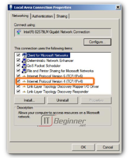 [/tab]
[tab]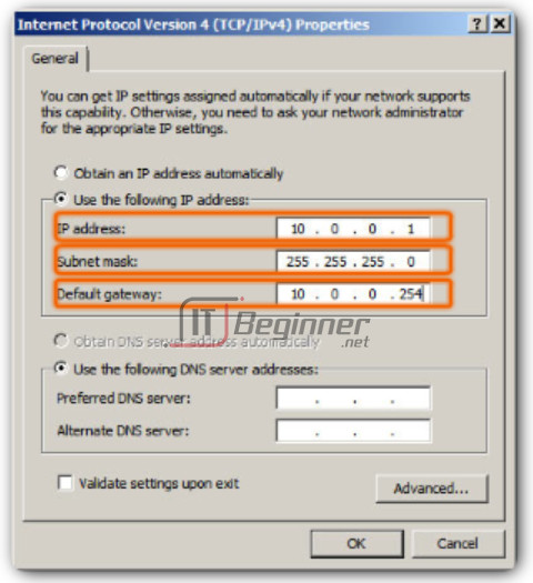 [/tab]
[/tabs]
8.1.3.2 Assigning a Dynamic IPv4 Address to a Host
Dynamic Assignment
On local networks it is often the case that the user population changes frequently. New users arrive with laptops and need a connection. Others have new workstations or other network devices, such as smart phones, that need to be connected. Rather than have the network administrator assign IP addresses for each workstation, it is easier to have IP addresses assigned automatically. This is done using a protocol known as Dynamic Host Configuration Protocol (DHCP), as shown in Figure 1.
DHCP enables the automatic assignment of addressing information such as IP address, subnet mask, default gateway, and other configuration information. The configuration of the DHCP server requires that a block of addresses, called an address pool, is used for assigning to the DHCP clients on a network. Addresses assigned to this pool should be planned so that they exclude any static addresses used by other devices.
DHCP is generally the preferred method of assigning IPv4 addresses to hosts on large networks because it reduces the burden on network support staff and virtually eliminates entry errors.
Another benefit of DHCP is that an address is not permanently assigned to a host but is only “leased” for a period of time. If the host is powered down or taken off the network, the address is returned to the pool for reuse. This feature is especially helpful for mobile users that come and go on a network.
If DCHP is enabled on a host device, the ipconfig command can be used to view the IP address information assigned by the DHCP server, as shown in Figure 2.
[tabs type=”horizontal”]
[tabs_head]
[tab_title]Assigning a Dynamic IPv4 Address[/tab_title]
[tab_title]Verifying a Dynamic IPv4 Address[/tab_title]
[/tabs_head]
[tab]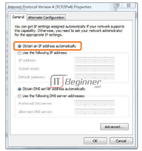 [/tab]
[tab]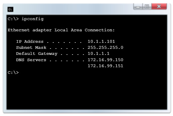 [/tab]
[/tabs]
8.1.3.3 Unicast Transmission
In an IPv4 network, the hosts can communicate one of three ways:
- Unicast – The process of sending a packet from one host to an individual host
- Broadcast – The process of sending a packet from one host to all hosts in the network
- Multicast – The process of sending a packet from one host to a selected group of hosts, possibly in different networks
These three types of communication are used for different purposes in data networks. In all three cases, the IPv4 address of the originating host is placed in the packet header as the source address.
Unicast Traffic
Unicast communication is used for normal host-to-host communication in both a client/server and a peer-to-peer network. Unicast packets use the addresses of the destination device as the destination address and can be routed through an internetwork.
Play the animation to see an example of unicast transmission.
In an IPv4 network, the unicast addresses applied to an end device is referred to as the host address. For unicast communication, the addresses assigned to the two end devices are used as the source and destination IPv4 addresses. During the encapsulation process, the source host places its IPv4 address in the unicast packet header as the source address and the IPv4 address of the destination host in the packet header as the destination address. Regardless of whether the destination specified a packet is a unicast, broadcast or multicast; the source address of any packet is always the unicast address of the originating host.
Note: In this course, all communications between devices is unicast communication unless otherwise noted.
IPv4 host addresses are unicast addresses and are in the address range of 0.0.0.0 to 223.255.255.255. However, within this range are many addresses that are reserved for special purposes. These special purpose addresses will be discussed later in this chapter.
![]()
8.1.3.4 Broadcast Transmission
Broadcast Transmission
Broadcast traffic is used to send packets to all hosts in the network using the broadcast address for the network. With a broadcast, the packet contains a destination IP address with all ones (1s) in the host portion. This means that all hosts on that local network (broadcast domain) will receive and look at the packet. Many network protocols, such as DHCP, use broadcasts. When a host receives a packet sent to the network broadcast address, the host processes the packet as it would a packet addressed to its unicast address.
Some examples for using broadcast transmission are:
- Mapping upper layer addresses to lower layer addresses
- Requesting an address
- Unlike unicast, where the packets can be routed throughout the internetwork, broadcast packets are usually restricted to the local network. This restriction is dependent on the configuration of the gateway router and the type of broadcast. There are two types of broadcasts: directed broadcast and limited broadcast.
Directed Broadcast
A directed broadcast is sent to all hosts on a specific network. This type of broadcast is useful for sending a broadcast to all hosts on a non-local network. For example, for a host outside of the 172.16.4.0/24 network to communicate with all of the hosts within that network, the destination address of the packet would be 172.16.4.255. Although routers do not forward directed broadcasts by default, they may be configured to do so.
Limited Broadcast
The limited broadcast is used for communication that is limited to the hosts on the local network. These packets always use a destination IPv4 address 255.255.255.255. Routers do not forward a limited broadcast. For this reason, an IPv4 network is also referred to as a broadcast domain. Routers form the boundary for a broadcast domain.
As an example, a host within the 172.16.4.0/24 network would broadcast to all hosts in its network using a packet with a destination address of 255.255.255.255.
Play the animation to see an example of a limited broadcast transmission.
When a packet is broadcast, it uses resources on the network and causes every receiving host on the network to process the packet. Therefore, broadcast traffic should be limited so that it does not adversely affect performance of the network or devices. Because routers separate broadcast domains, subdividing networks with excessive broadcast traffic can improve network performance.
8.1.3.5 Multicast Transmission
Multicast Transmission
Multicast transmission is designed to conserve the bandwidth of an IPv4 network. It reduces traffic by allowing a host to send a single packet to a selected set of hosts that are part of a subscribing multicast group. To reach multiple destination hosts using unicast communication, a source host would need to send an individual packet addressed to each host. With multicast, the source host can send a single packet that can reach thousands of destination hosts. The internetwork’s responsibility is to replicate the multicast flows in an efficient manner so that they reach only their intended recipients.
Some examples of multicast transmission are:
- Video and audio broadcasts
- Routing information exchange by routing protocols
- Distribution of software
- Remote gaming
Multicast Addresses
IPv4 has a block of addresses reserved for addressing multicast groups. This address range is 224.0.0.0 to 239.255.255.255. The multicast address range is subdivided into different types of addresses: reserved link local addresses and globally scoped addresses. One additional type of multicast address is the administratively scoped addresses, also called limited scope addresses.
The IPv4 multicast addresses 224.0.0.0 to 224.0.0.255 are reserved link local addresses. These addresses are to be used for multicast groups on a local network. A router connected to the local network recognizes that these packets are addressed to a link-local multicast group and never forwards them further. A typical use of reserved link-local addresses is in routing protocols using multicast transmission to exchange routing information.
The globally scoped addresses are 224.0.1.0 to 238.255.255.255. They may be used to multicast data across the Internet. For example, 224.0.1.1 has been reserved for the Network Time Protocol (NTP) to synchronize the time-of-day clocks of network devices.
Multicast Clients
Hosts that receive particular multicast data are called multicast clients. The multicast clients use services requested by a client program to subscribe to the multicast group.
Each multicast group is represented by a single IPv4 multicast destination address. When an IPv4 host subscribes to a multicast group, the host processes packets addressed to this multicast address and packets addressed to its uniquely allocated unicast address.
The animation demonstrates clients accepting multicast packets.
![]()
8.1.3.6 Activity – Unicast, Broadcast, or Multicast
8.1.3.7 Activity – Calculate the Network, Broadcast and Host Addresses
8.1.3.8 Packet Tracer – Investigate Unicast, Broadcast, and Multicast Traffic
This activity will examine unicast, broadcast, and multicast behavior. Most traffic in a network is unicast. When a PC sends an ICMP echo request to a remote router, the source address in the IP packet header is the IP address of the sending PC. The destination address in the IP packet header is the IP address of the interface on the remote router. The packet is sent only to the intended destination.
Using the ping command or the Add Complex PDU feature of Packet Tracer, you can directly ping broadcast addresses to view broadcast traffic.
For multicast traffic, you will view EIGRP traffic. EIGRP is used by Cisco routers to exchange routing information between routers. Routers using EIGRP send packets to multicast address 224.0.0.10, which represents the group of EIGRP routers. Although these packets are received by other devices, they are dropped at Layer 3 by all devices except EIGRP routers, with no other processing required.
Packet Tracer – Investigate Unicast, Broadcast, and Multicast Traffic Instructions ./.
Packet Tracer – Investigate Unicast, Broadcast, and Multicast Traffic – PKA ./.
8.1.4 Types of IPv4 Addresses
8.1.4.1 Public and Private IPv4 Addresses
Although most IPv4 host addresses are public addresses designated for use in networks that are accessible on the Internet, there are blocks of addresses that are used in networks that require limited or no Internet access. These addresses are called private addresses.
Private Addresses
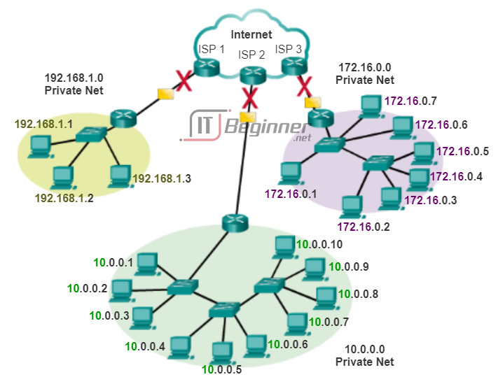
The private address blocks are:
10.0.0.0 to 10.255.255.255 (10.0.0.0/8)
172.16.0.0 to 172.31.255.255 (172.16.0.0/12)
192.168.0.0 to 192.168.255.255 (192.168.0.0/16)
Private addresses are defined in RFC 1918, Address Allocation for Private Internets, and are sometimes referred to as RFC 1918 addresses. Private space address blocks, as shown in the figure, are used in private networks. Hosts that do not require access to the Internet can use private addresses. However within the private network, hosts still require unique IP addresses within the private space.
Hosts in different networks may use the same private space addresses. Packets using these addresses as the source or destination should not appear on the public Internet. The router or firewall device at the perimeter of these private networks must block or translate these addresses. Even if these packets were to make their way to the Internet, the routers would not have routes to forward them to the appropriate private network.
In RFC 6598, IANA reserved another group of addresses known as shared address space. Similar to RFC 1918 private address space, shared address space addresses are not globally routable. However, these addresses are intended only for use in service provider networks. The shared address block is 100.64.0.0/10.
Public Addresses
The vast majority of the addresses in the IPv4 unicast host range are public addresses. These addresses are designed to be used in the hosts that are publicly accessible from the Internet. Even within these IPv4 address blocks, there are many addresses that are designated for other special purposes.
8.1.4.2 Activity – Pass or Block IPv4 Addresses
8.1.4.3 Special Use IPv4 Addresses
There are certain addresses that cannot be assigned to hosts. There are also special addresses that can be assigned to hosts, but with restrictions on how those hosts can interact within the network.
Network and Broadcast Addresses
As explained earlier, within each network the first and last addresses cannot be assigned to hosts. These are the network address and the broadcast address, respectively.
Loopback
One such reserved address is the IPv4 loopback address 127.0.0.1. The loopback is a special address that hosts use to direct traffic to themselves. The loopback address creates a shortcut method for TCP/IP applications and services that run on the same device to communicate with one another. By using the loopback address instead of the assigned IPv4 host address, two services on the same host can bypass the lower layers of the TCP/IP stack. You can also ping the loopback address to test the configuration of TCP/IP on the local host.
Although only the single 127.0.0.1 address is used, addresses 127.0.0.0 to 127.255.255.255 are reserved. Any address within this block will loop back to the local host. No address within this block should ever appear on any network.
Link-Local Addresses
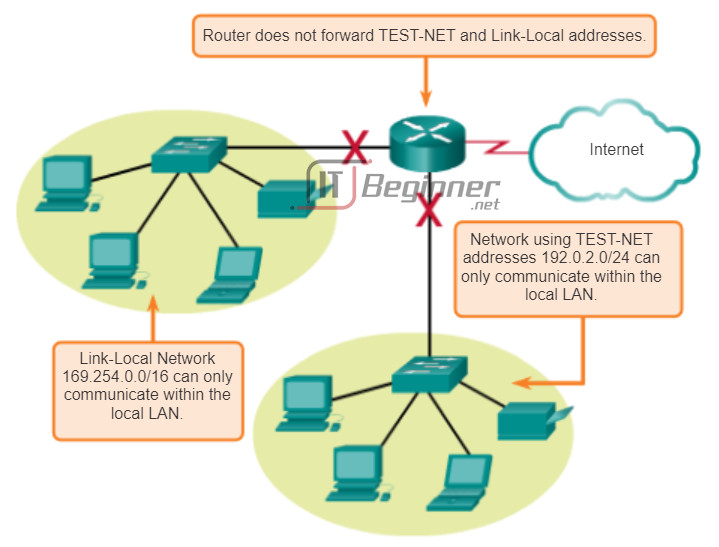
IPv4 addresses in the address block 169.254.0.0 to 169.254.255.255 (169.254.0.0/16) are designated as link-local addresses. These addresses can be automatically assigned to the local host by the operating system in environments where no IP configuration is available. These might be used in a small peer-to-peer network or for a host that could not automatically obtain an address from a DHCP server.
Communication using IPv4 link-local addresses is only suitable for communication with other devices connected to the same network, as shown in the figure. A host must not send a packet with an IPv4 link-local destination address to any router for forwarding and should set the IPv4 time to live (TTL) for these packets to 1.
Link-local addresses do not provide services outside of the local network. However, many client/server and peer-to-peer applications will work properly with IPv4 link-local addresses.
TEST-NET Addresses
The address block 192.0.2.0 to 192.0.2.255 (192.0.2.0/24) is set aside for teaching and learning purposes. These addresses can be used in documentation and network examples. Unlike the experimental addresses, network devices will accept these addresses in their configurations. You may often find these addresses used with the domain names example.com or example.net in RFCs, vendor, and protocol documentation. Addresses within this block should not appear on the Internet.
Experimental Addresses
The addresses in the block 240.0.0.0 to 255.255.255.254 are listed as reserved for future use (RFC 3330). Currently, these addresses can only be used for research or experimentation purposes, but cannot be used in an IPv4 network. Though, according to RFC 3330, they could, technically, be converted to usable addresses in the future.
8.1.4.4 Legacy Classful Addressing
Historically, RFC1700, Assigned Numbers, grouped the unicast ranges into specific sizes called class A, class B, and class C addresses. It also defined class D (multicast) and class E (experimental) addresses, as previously presented. The unicast address classes A, B, and C defined specifically-sized networks and specific address blocks for these networks. A company or organization was assigned an entire network from class A, class B, or class C address block. This use of address space is referred to as classful addressing.
Class A Blocks
A class A address block was designed to support extremely large networks with more than 16 million host addresses. Class A IPv4 addresses used a fixed /8 prefix with the first octet to indicate the network address. The remaining three octets were used for host addresses. All class A addresses required that the most significant bit of the high-order octet be a zero. This meant that there were only 128 possible class A networks, 0.0.0.0/8 to 127.0.0.0/8. Even though the class A addresses reserved one-half of the address space, because of their limit of 128 networks, they could only be allocated to approximately 120 companies or organizations.
Class B Blocks
Class B address space was designed to support the needs of moderate to large size networks with up to approximately 65,000 hosts. A class B IP address used the two high-order octets to indicate the network address. The other two octets specified host addresses. As with class A, address space for the remaining address classes needed to be reserved. For class B addresses, the most significant two bits of the high-order octet were 10. This restricted the address block for class B to 128.0.0.0/16 to 191.255.0.0/16. Class B had slightly more efficient allocation of addresses than class A because it equally divided 25% of the total IPv4 address space among approximately 16,000 networks.
Class C Blocks
The class C address space was the most commonly available of the historic address classes. This address space was intended to provide addresses for small networks with a maximum of 254 hosts. Class C address blocks used a /24 prefix. This meant that a class C network used only the last octet as host addresses with the three high-order octets used to indicate the network address. Class C address blocks set aside address space by using a fixed value of 110 for the three most significant bits of the high-order octet. This restricted the address block for class C from 192.0.0.0/24 to 223.255.255.0/24. Although it occupied only 12.5% of the total IPv4 address space, it could provide addresses to 2 million networks.
Figure 1 illustrates how these address classes are divided.
Limits to the Class-based System
Not all organizations’ requirements fit well into one of these three classes. Classful allocation of address space often wasted many addresses, which exhausted the availability of IPv4 addresses. For example, a company that had a network with 260 hosts would need to be given a class B address with more than 65,000 addresses.
Even though this classful system was all but abandoned in the late 1990s, you will see remnants of it in networks today. For example, when you assign an IPv4 address to a computer, the operating system examines the address being assigned to determine if this address is a class A, class B, or class C. The operating system then assumes the prefix used by that class and makes the default subnet mask assignment.
Classless Addressing
The system in use today is referred to as classless addressing. The formal name is Classless Inter-Domain Routing (CIDR, pronounced “cider”). The classful allocation of IPv4 addresses was very inefficient, allowing for only /8, /16 or /24 prefix lengths, each from a separate address space. In 1993, the IETF created a new set of standards that allowed service providers to allocate IPv4 addresses on any address bit boundary (prefix length) instead of only by a class A, B, or C address.
The IETF knew that CIDR was only a temporary solution and that a new IP protocol would have to be developed to accommodate the rapid growth in the number of Internet users. In 1994, the IETF began its work to find a successor to IPv4, which eventually became IPv6.
Figure 2 shows the classful address ranges.
[tabs type=”horizontal”]
[tabs_head]
[tab_title]Figure 1[/tab_title]
[tab_title]Figure 2[/tab_title]
[/tabs_head]
[tab]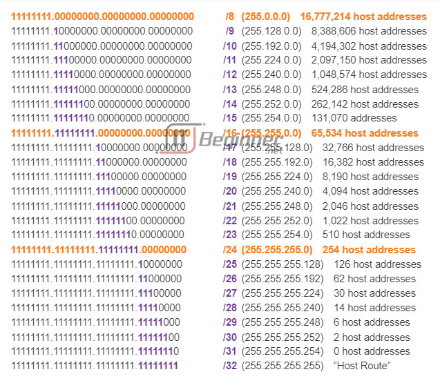 [/tab]
[tab]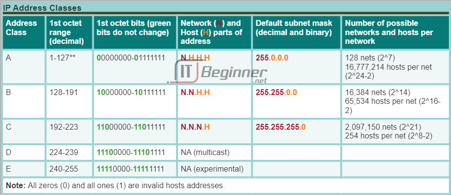 [/tab]
[/tabs]
8.1.4.5 Assignment of IP Addresses
For a company or organization to have network hosts, such as web servers, accessible from the Internet, that organization must have a block of public addresses assigned. Remember that public addresses must be unique, and use of these public addresses is regulated and allocated to each organization separately. This is true for IPv4 and IPv6 addresses.
IANA and RIRs
Internet Assigned Numbers Authority (IANA) (http://www.iana.org) manages the allocation of IPv4 and IPv6 addresses. Until the mid-1990s, all IPv4 address space was managed directly by the IANA. At that time, the remaining IPv4 address space was allocated to various other registries to manage for particular purposes or for regional areas. These registration companies are called Regional Internet Registries (RIRs), as shown in the figure.
The major registries are:
- AfriNIC (African Network Information Centre) – Africa Region http://www.afrinic.net
- APNIC (Asia Pacific Network Information Centre) – Asia/Pacific Region http://www.apnic.net
- ARIN (American Registry for Internet Numbers) – North America Region http://www.arin.net
- LACNIC (Regional Latin-American and Caribbean IP Address Registry) – Latin America and some Caribbean Islands http://www.lacnic.net
- RIPE NCC (Reseaux IP Europeans) – Europe, the Middle East, and Central Asia http://www.ripe.net
ISPs
RIRs are responsible for allocating IP addresses to the Internet Service Providers (ISPs). Most companies or organizations obtain their IPv4 address blocks from an ISP. An ISP will generally supply a small number of usable IPv4 addresses (6 or 14) to their customers as a part of their services. Larger blocks of addresses can be obtained based on justification of needs and for additional service costs.
In a sense, the ISP loans or rents these addresses to the organization. If we choose to move our Internet connectivity to another ISP, the new ISP will provide us with addresses from the address blocks that have been provided to them, and our previous ISP returns the blocks loaned to us to their allocation to be loaned to another customer.
IPv6 addresses can be obtained from the ISP or in some cases directly from the RIR. IPv6 addresses and typical address block sizes will be discussed later in this chapter.

8.1.4.6 Assignment of IP Addresses (Cont.)
ISP Services
To get access to the services of the Internet, we have to connect our data network to the Internet using an Internet Service Provider (ISP).
ISPs have their own set of internal data networks to manage Internet connectivity and to provide related services. Among the other services that an ISP generally provides to its customers are DNS services, email services, and a website. Depending on the level of service required and available, customers use different tiers of an ISP.
ISP Tiers
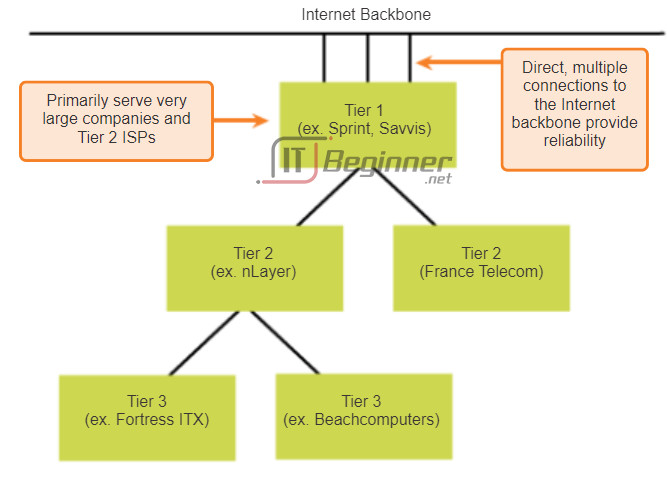
ISPs are designated by a hierarchy based on their level of connectivity to the Internet backbone. Each lower tier obtains connectivity to the backbone via a connection to a higher tier ISP, as shown in the figures.
Tier 1
As shown in Figure 1, at the top of the ISP hierarchy are Tier 1 ISPs. These ISPs are large national or international ISPs that are directly connected to the Internet backbone. The customers of Tier 1 ISPs are either lower-tiered ISPs or large companies and organizations. Because they are at the top of Internet connectivity, they engineer highly reliable connections and services. Among the technologies used to support this reliability are multiple connections to the Internet backbone.
The primary advantages for customers of Tier 1 ISPs are reliability and speed. Because these customers are only one connection away from the Internet, there are fewer opportunities for failures or traffic bottlenecks. The drawback for Tier 1 ISP customers is its high cost.
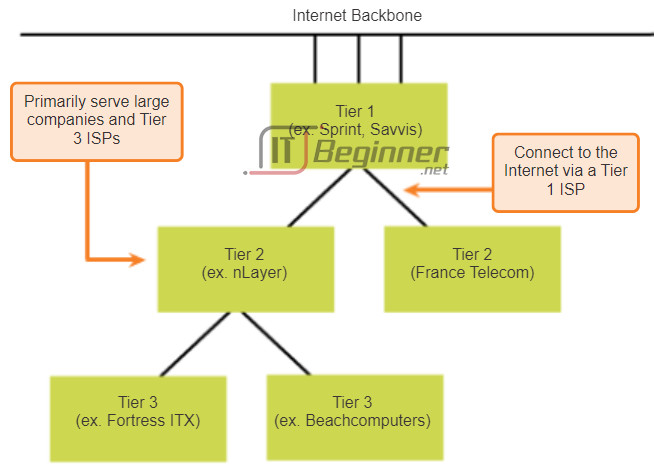
Tier 2
As shown in Figure 2, Tier 2 ISPs acquire their Internet service from Tier 1 ISPs. Tier 2 ISPs generally focus on business customers. Tier 2 ISPs usually offer more services than the other two tiers of ISPs. These Tier 2 ISPs tend to have the IT resources to operate their own services such as DNS, email servers, and web servers. Other services that Tier 2 ISPs may offer include website development and maintenance, e-commerce/e-business, and VoIP.
The primary disadvantage of Tier 2 ISPs, as compared to Tier 1 ISPs, is slower Internet access. Because Tier 2 ISPs are at least one more connection away from the Internet backbone, they also tend to have lower reliability than Tier 1 ISPs.
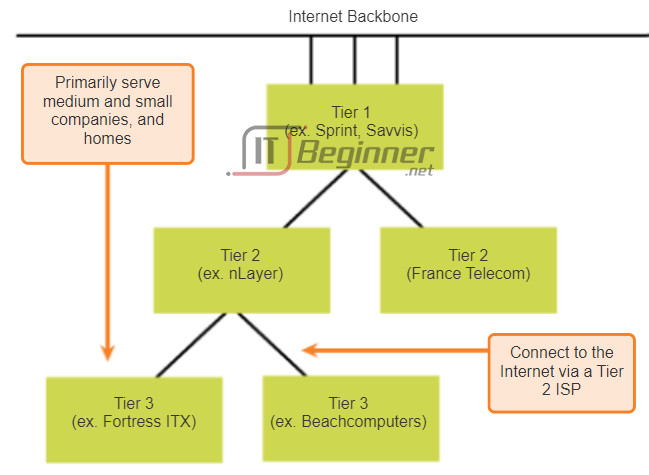
Tier 3
As shown in Figure 3, Tier 3 ISPs purchase their Internet service from Tier 2 ISPs. The focus of these ISPs is the retail and home markets in a specific locale. Tier 3 customers typically do not need many of the services required by Tier 2 customers. Their primary need is connectivity and support.
These customers often have little or no computer or network expertise. Tier 3 ISPs often bundle Internet connectivity as a part of network and computer service contracts for their customers. While they may have reduced bandwidth and less reliability than Tier 1 and Tier 2 providers, they are often good choices for small to medium size companies.
[tabs type=”horizontal”]
[tabs_head]
[tab_title]Tier 1[/tab_title]
[tab_title]Tier 2[/tab_title]
[tab_title]Tier 3[/tab_title]
[/tabs_head]
[tab]
[/tab]
[tab]
[/tab]
[tab]
[/tab]
[/tabs]
8.1.4.7 Activity – Public or Private IPv4 Addresses
8.1.4.8 Lab – Identifying IPv4 Addresses
In this lab, you will complete the following objectives:
- Part 1: Identify IPv4 Addresses
- Part 2: Classify IPv4 Addresses
Lab – Identifying IPv4 Addresses ./.
8.2 IPv6 Network Addresses
8.2.1 IPv4 issues
8.2.1.1 The Need for IPv6
IPv6 is designed to be the successor to IPv4. IPv6 has a larger 128-bit address space, providing for 340 undecillion addresses. (That is the number 340, followed by 36 zeroes.) However, IPv6 is much more than just larger addresses. When the IETF began its development of a successor to IPv4, it used this opportunity to fix the limitations of IPv4 and include additional enhancements. One example is Internet Control Message Protocol version 6 (ICMPv6), which includes address resolution and address auto-configuration not found in ICMP for IPv4 (ICMPv4). ICMPv4 and ICMPv6 will be discussed later in this chapter.
Need for IPv6
The depletion of IPv4 address space has been the motivating factor for moving to IPv6. As Africa, Asia and other areas of the world become more connected to the Internet, there are not enough IPv4 addresses to accommodate this growth. On Monday, January 31, 2011, IANA allocated the last two /8 IPv4 address blocks to the Regional Internet Registries (RIRs). Various projections show that all five RIRs will have run out of IPv4 addresses between 2015 and 2020. At that point, the remaining IPv4 addresses will have been allocated to ISPs.
IPv4 has theoretical maximum of 4.3 billion addresses. RFC 1918 private addresses in combination with Network Address Translation (NAT) have been instrumental in slowing the depletion of IPv4 address space. NAT has limitations that severely impede peer-to-peer communications.
Internet of Things
The Internet of today is significantly different than the Internet of past decades. The Internet of today is more than email, web pages and file transfer between computers. The evolving Internet is becoming an Internet of things. No longer will the only devices accessing the Internet be computers, tablets and smart phones. The sensor-equipped, Internet-ready devices of tomorrow will include everything from automobiles and biomedical devices, to household appliances and natural ecosystems. Imagine a meeting at a customer site that is automatically scheduled on your calendar application, to begin an hour before you normally start work. This could be a significant problem, especially if you forget to check the calendar or adjust the alarm clock accordingly. Now imagine that the calendar application communicates this information directly to your alarm clock for you and to your automobile. Your car automatically warms up to melt the ice on the windshield before you enter the car and reroutes you to your meeting.
With an increasing Internet population, a limited IPv4 address space, issues with NAT and an Internet of things, the time has come to begin the transition to IPv6.
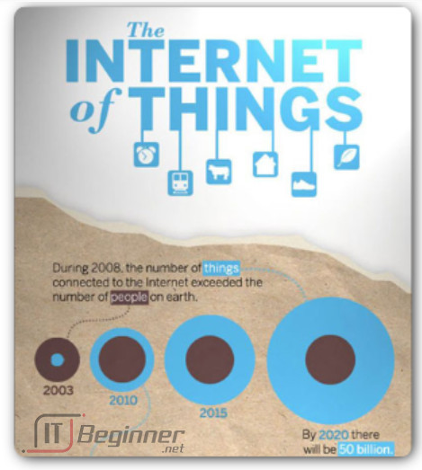
To view this infographic in its entirety, go to:
http://share.cisco.com/internet-of-things.html
8.2.1.2 IPv4 and IPv6 Coexistence
There is not a single date to move to IPv6. For the foreseeable future, both IPv4 and IPv6 will coexist. The transition is expected to take years. The IETF has created various protocols and tools to help network administrators migrate their networks to IPv6. The migration techniques can be divided into three categories:
- Dual Stack – As shown in Figure 1, dual stack allows IPv4 and IPv6 to coexist on the same network. Dual stack devices run both IPv4 and IPv6 protocol stacks simultaneously.
- Tunneling – As shown in Figure 2, tunneling is a method of transporting an IPv6 packet over an IPv4 network. The IPv6 packet is encapsulated inside an IPv4 packet, similar to other types of data.
- Translation – As shown in Figure 3, Network Address Translation 64 (NAT64) allows IPv6-enabled devices to communicate with IPv4-enabled devices using a translation technique similar to NAT for IPv4. An IPv6 packet is translated to an IPv4 packet, and vice versa.
[tabs type=”horizontal”]
[tabs_head]
[tab_title]Dual-Stack[/tab_title]
[tab_title]Tunnelling[/tab_title]
[tab_title]Translation[/tab_title]
[/tabs_head]
[tab]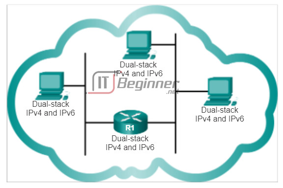 [/tab]
[tab]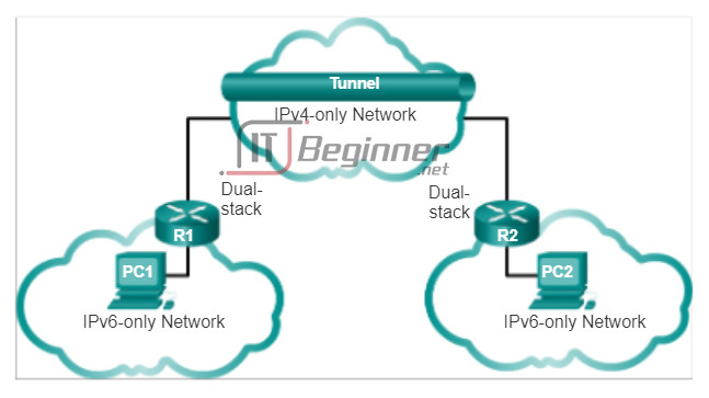 [/tab]
[tab]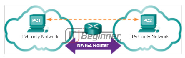 [/tab]
[/tabs]
8.2.1.3 Activity – IPv4 Issues and Solutions
8.2.2 IPv6 Addressing
8.2.2.1 Hexadecimal Number System
Unlike IPv4 addresses that are expressed in dotted decimal notation, IPv6 addresses are represented using hexadecimal values. You have seen hexadecimal used in the Packets Byte pane of Wireshark. In Wireshark, hexadecimal is used to represent the binary values within frames and packets. Hexadecimal is also used to represent Ethernet Media Access Control (MAC) addresses.
Hexadecimal Numbering
Hexadecimal (“Hex”) is a convenient way to represent binary values. Just as decimal is a base ten numbering system and binary is base two, hexadecimal is a base sixteen system.
The base 16 numbering system uses the numbers 0 to 9 and the letters A to F. Figure 1 shows the equivalent decimal, binary, and hexadecimal values. There are 16 unique combinations of four bits, from 0000 to 1111. The 16 digit Hexadecimal is the perfect number system to use, because any four bits can be represented with a single hexadecimal value.
Understanding Bytes
Given that 8 bits (a byte) is a common binary grouping, binary 00000000 to 11111111 can be represented in hexadecimal as the range 00 to FF. Leading zeroes can be displayed to complete the 8-bit representation. For example, the binary value 0000 1010 is shown in hexadecimal as 0A.
Representing Hexadecimal Values
Note: It is important to distinguish hexadecimal values from decimal values regarding the characters 0 to 9.
Hexadecimal is usually represented in text by the value preceded by 0x (for example 0x73) or a subscript 16. Less commonly, it may be followed by an H, for example 73H. However, because subscript text is not recognized in command line or programming environments, the technical representation of hexadecimal is preceded with “0x” (zero X). Therefore, the examples above would be shown as 0x0A and 0x73 respectively.
Hexadecimal Conversions
Number conversions between decimal and hexadecimal values are straightforward, but quickly dividing or multiplying by 16 is not always convenient.
With practice, it is possible to recognize the binary bit patterns that match the decimal and hexadecimal values. Figure 2 shows these patterns for selected 8-bit values.
[tabs type=”horizontal”]
[tabs_head]
[tab_title]Figure 1[/tab_title]
[tab_title]Figure 2[/tab_title]
[/tabs_head]
[tab]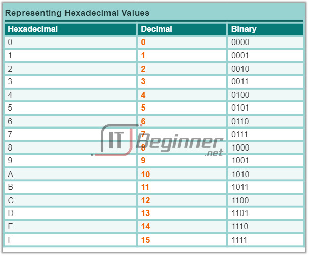 [/tab]
[tab]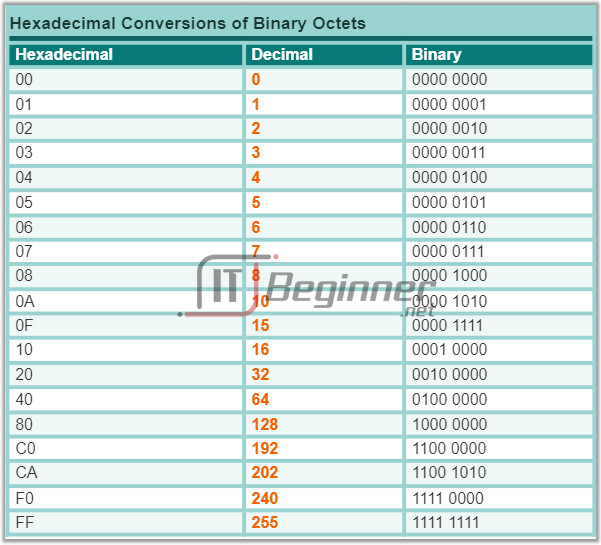 [/tab]
[/tabs]
8.2.2.2 IPv6 Address Representation
IPv6 addresses are 128 bits in length and written as a string of hexadecimal values. Every 4 bits is represented by a single hexadecimal digit; for a total of 32 hexadecimal values. IPv6 addresses are not case sensitive and can be written in either lowercase or uppercase.
Preferred Format
As shown in Figure 1, the preferred format for writing an IPv6 address is x:x:x:x:x:x:x:x, with each “x” consisting of four hexadecimal values. When referring to 8 bits of an IPv4 address we use the term octet. In IPv6, a hextet is the unofficial term used to refer to a segment of 16 bits or four hexadecimal values. Each “x” is a single hextet, 16 bits or four hexadecimal digits.
Preferred format means the IPv6 address is written using all 32 hexadecimal digits. It does not necessarily mean it is the ideal method for representing the IPv6 address. In the following pages, we will see two rules to help reduce the number of digits needed to represent an IPv6 address.
Figure 2 has examples of IPv6 addresses in the preferred format.
[tabs type=”horizontal”]
[tabs_head]
[tab_title]Hextets[/tab_title]
[tab_title]Preferred Format Examples[/tab_title]
[/tabs_head]
[tab]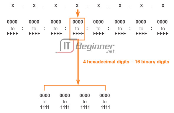 [/tab]
[tab]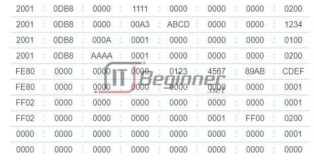 [/tab]
[/tabs]
8.2.2.3 Rule 1 – Omitting Leading 0s
The first rule to help reduce the notation of IPv6 addresses is any leading 0s (zeros) in any 16-bit section or hextet can be omitted. For example:
- 01AB can be represented as 1AB
- 09F0 can be represented as 9F0
- 0A00 can be represented as A00
- 00AB can be represented as AB
This rule only applies to leading 0s, NOT to trailing 0s, otherwise the address would be ambiguous. For example, the hextet “ABC” could be either “0ABC” or “ABC0”.
The Figures 1 to 8 show several examples of how omitting leading 0s can be used to reduce the size of an IPv6 address. For each example the preferred format is shown. Notice how omitting the leading 0s in most examples results in a smaller address representation.
[tabs type=”horizontal”]
[tabs_head]
[tab_title]Figures 1[/tab_title]
[tab_title]Figures 2[/tab_title]
[tab_title]Figures 3[/tab_title]
[tab_title]Figures 4[/tab_title]
[tab_title]Figures 5[/tab_title]
[tab_title]Figures 6[/tab_title]
[tab_title]Figures 7[/tab_title]
[tab_title]Figures 8[/tab_title]
[/tabs_head]
[tab]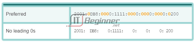 [/tab]
[tab]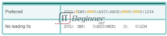 [/tab]
[tab]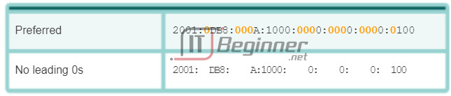 [/tab]
[tab]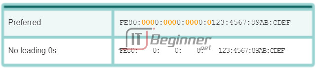 [/tab]
[tab]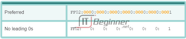 [/tab]
[tab]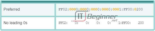 [/tab]
[tab]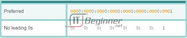 [/tab]
[tab]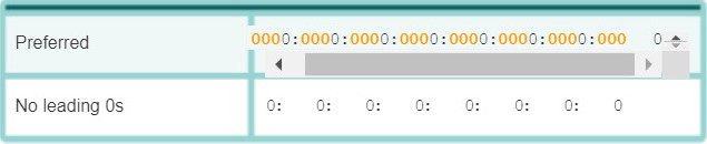 [/tab]
[/tabs]
8.2.2.4 Rule 2 – Omitting All 0 Segments
The second rule to help reduce the notation of IPv6 addresses is that a double colon (::) can replace any single, contiguous string of one or more 16-bit segments (hextets) consisting of all 0s.
The double colon (::) can only be used once within an address, otherwise there would be more than one possible resulting address. When used with the omitting leading 0s technique, the notation of IPv6 address can often be greatly reduced. This is commonly known as the compressed format.
Incorrect address:
- 2001:0DB8::ABCD::1234
Possible expansions of ambiguous compressed addresses:
- 2001:0DB8::ABCD:0000:0000:1234
- 2001:0DB8::ABCD:0000:0000:0000:1234
- 2001:0DB8:0000:ABCD::1234
- 2001:0DB8:0000:0000:ABCD::1234
The Figures 1 to 7 show several examples of the how using the double colon (::) and omitting leading 0s can reduce the size of an IPv6 address.
[tabs type=”horizontal”]
[tabs_head]
[tab_title]Figures 1[/tab_title]
[tab_title]Figures 2[/tab_title]
[tab_title]Figures 3[/tab_title]
[tab_title]Figures 4[/tab_title]
[tab_title]Figures 5[/tab_title]
[tab_title]Figures 6[/tab_title]
[tab_title]Figures 7[/tab_title]
[/tabs_head]
[tab]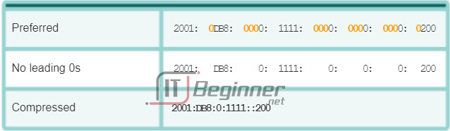 [/tab]
[tab]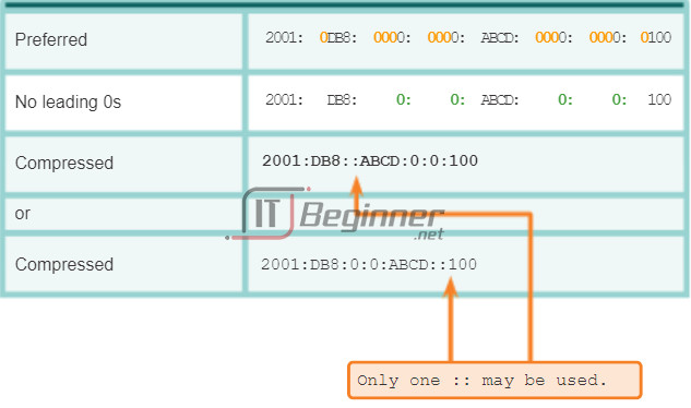 [/tab]
[tab]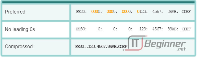 [/tab]
[tab]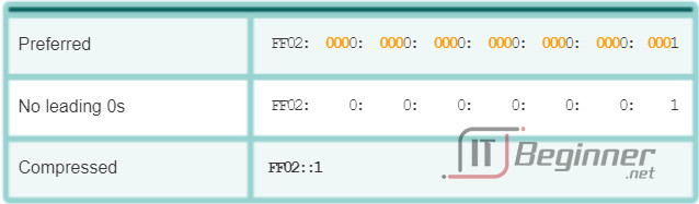 [/tab]
[tab]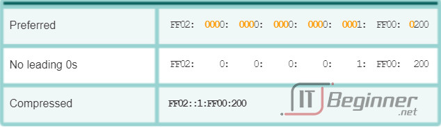 [/tab]
[tab]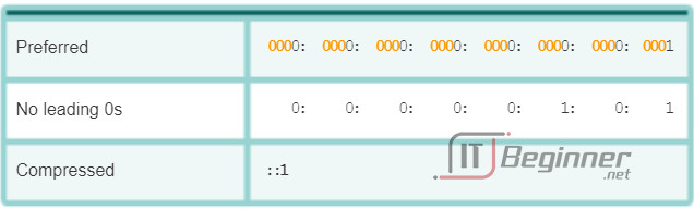 [/tab]
[tab]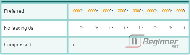 [/tab]
[/tabs]
8.2.2.5 Activity – Practicing IPv6 Address Representations
8.2.3 Types of IPv6 Addresses
8.2.3.1 IPv6 Address Types
There are three types of IPv6 addresses:
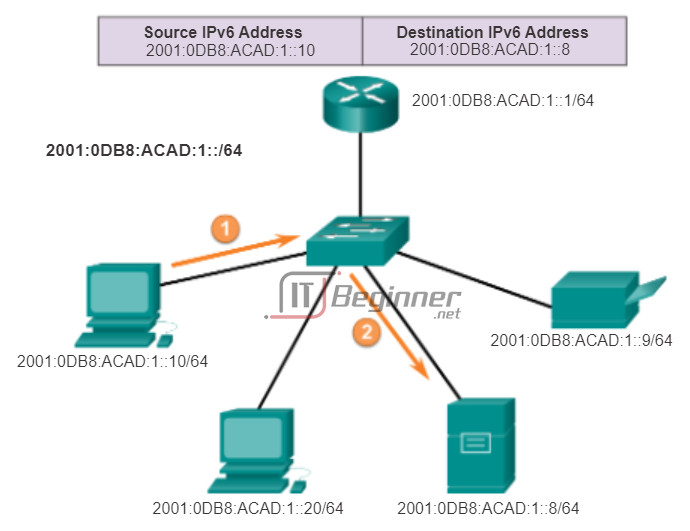
- Unicast – An IPv6 unicast address uniquely identifies an interface on an IPv6-enabled device. As shown in the figure, a source IPv6 address must be a unicast address.
- Multicast – An IPv6 multicast address is used to send a single IPv6 packet to multiple destinations.
- Anycast – An IPv6 anycast address is any IPv6 unicast address that can be assigned to multiple devices. A packet sent to an anycast address is routed to the nearest device having that address. Anycast addresses are beyond the scope of this course.
Unlike IPv4, IPv6 does not have a broadcast address. However, there is an IPv6 all-nodes multicast address that essentially gives the same result.
8.2.3.2 IPv6 Prefix Length
Recall that the prefix, or network portion, of an IPv4 address can be identified by a dotted-decimal subnet mask or prefix length (slash notation). For example, an IP address of 192.168.1.10 with dotted-decimal subnet mask 255.255.255.0 is equivalent to 192.168.1.10/24.
IPv6 uses the prefix length to represent the prefix portion of the address. IPv6 does not use the dotted-decimal subnet mask notation. The prefix length is used to indicate the network portion of an IPv6 address using the IPv6 address/prefix length.
The prefix length can range from 0 to 128. A typical IPv6 prefix length for LANs and most other types of networks is /64. This means the prefix or network portion of the address is 64 bits in length, leaving another 64 bits for the interface ID (host portion) of the address.
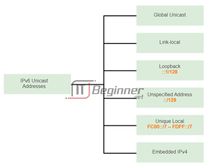
8.2.3.3 IPv6 Unicast Addresses
An IPv6 unicast address uniquely identifies an interface on an IPv6-enabled device. A packet sent to a unicast address is received by the interface that is assigned that address. Similar to IPv4, a source IPv6 address must be a unicast address. The destination IPv6 address can be either a unicast or a multicast address.
There are six types of IPv6 unicast addresses.
Global unicast
A global unicast address is similar to a public IPv4 address. These are globally unique, Internet routable addresses. Global unicast addresses can be configured statically or assigned dynamically. There are some important differences in how a device receives its IPv6 address dynamically compared to DHCP for IPv4.
Link-local
Link-local addresses are used to communicate with other devices on the same local link. With IPv6, the term link refers to a subnet. Link-local addresses are confined to a single link. Their uniqueness must only be confirmed on that link because they are not routable beyond the link. In other words, routers will not forward packets with a link-local source or destination address.
Loopback
The loopback address is used by a host to send a packet to itself and cannot be assigned to a physical interface. Similar to an IPv4 loopback address, you can ping an IPv6 loopback address to test the configuration of TCP/IP on the local host. The IPv6 loopback address is all-0s except for the last bit, represented as ::1/128 or just ::1 in the compressed format.
Unspecified address
An unspecified address is an all-0s address represented in the compressed format as ::/128 or just :: in the compressed format. It cannot be assigned to an interface and is only be used as a source address in an IPv6 packet. An unspecified address is used as a source address when the device does not yet have a permanent IPv6 address or when the source of the packet is irrelevant to the destination.
Unique local
IPv6 unique local addresses have some similarity to RFC 1918 private addresses for IPv4, but there are significant differences as well. Unique local addresses are used for local addressing within a site or between a limited number of sites. These addresses should not be routable in the global IPv6. Unique local addresses are in the range of FC00::/7 to FDFF::/7.
With IPv4, private addresses are combined with NAT/PAT to provide a many-to-one translation of private-to-public addresses. This is done because of the limited availability of IPv4 address space. Many sites also use the private nature of RFC 1918 addresses to help secure or hide their network from potential security risks. However, this was never the intended use of these technologies and the IETF has always recommended that sites take the proper security precautions on their Internet facing router. Although, IPv6 does provide for site specific addressing, it is not intended to be used to help hide internal IPv6-enabled devices from the IPv6 Internet. IETF recommends that limiting access to devices should be accomplished using proper, best-practice security measures.
Note: The original IPv6 specification defined site-local addresses for a similar purpose, using the prefix range FEC0::/10. There were several ambiguities in the specification and site-local addresses were deprecated by the IETF in favor of unique local addresses.
IPv4 embedded
The last type of unicast address type is the IPv4 embedded address. These addresses are used to help transition from IPv4 to IPv6. IPv4 embedded addresses are beyond the scope of this course.
8.2.3.4 IPv6 Link-Local Unicast Addresses
An IPv6 link-local address enables a device to communicate with other IPv6-enabled devices on the same link and only on that link (subnet). Packets with a source or destination link-local address cannot be routed beyond the link from where the packet originated.
Unlike IPv4 link-local addresses, IPv6 link-local addresses have a significant role in various aspects of the network. The global unicast address is not a requirement; however, every IPv6-enabled network interface is required to have a link-local address.
If a link-local address is not configured manually on an interface, the device will automatically create its own without communicating with a DHCP server. IPv6-enabled hosts create an IPv6 link-local address even if the device has not been assigned a global unicast IPv6 address. This allows IPv6-enabled devices to communicate with other IPv6-enabled devices on the same subnet. This includes communication with the default gateway (router).
IPv6 link-local addresses are in the FE80::/10 range. The /10 indicates that the first 10 bits are 1111 1110 10xx xxxx. The first hextet has a range of 1111 1110 1000 0000 (FE80) to 1111 1110 1011 1111 (FEBF).
Figure 1 shows an example of communication using IPv6 link-local addresses.
Figure 2 shows the format of an IPv6 link-local address.
IPv6 link-local addresses are also used by IPv6 routing protocols to exchange messages and as the next-hop address in the IPv6 routing table. Link-local addresses are discussed in more detail in a later course.
Note: Typically, it is the link-local address of the router and not the global unicast address that is used as the default gateway for other devices on the link.
[tabs type=”horizontal”]
[tabs_head]
[tab_title]IPv6 Link-Local Communications[/tab_title]
[tab_title]IPv6 Link-Local Address[/tab_title]
[/tabs_head]
[tab]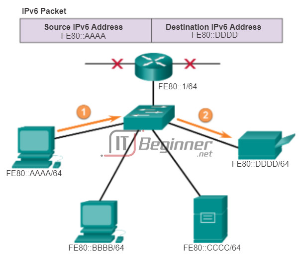 [/tab]
[tab]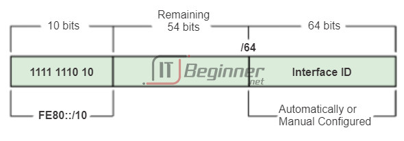 [/tab]
[/tabs]
8.2.3.5 Activity – Identify Types of IPv6 Addresses
8.2.4 IPv6 Unicast Addresses
8.2.4.1 Structure of an IPv6 Global Unicast Address
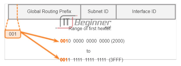
IPv6 global unicast addresses are globally unique and routable on the IPv6 Internet. These addresses are equivalent to public IPv4 addresses. The Internet Committee for Assigned Names and Numbers (ICANN), the operator for Internet Assigned Numbers Authority (IANA), allocates IPv6 address blocks to the five RIRs. Currently, only global unicast addresses with the first three bits of 001 or 2000::/3 are being assigned. This is only 1/8th of the total available IPv6 address space, excluding only a very small portion for other types of unicast and multicast addresses.
Note: The 2001:0DB8::/32 address has been reserved for documentation purposes, including use in examples.
Figure 1 shows the structure and range of a global unicast address.
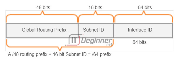
A global unicast address has three parts:
- Global routing prefix
- Subnet ID
- Interface ID
Global Routing Prefix
The global routing prefix is the prefix, or network, portion of the address that is assigned by the provider, such as an ISP, to a customer or site. Currently, RIRs assign a /48 global routing prefix to customers. This includes everyone from enterprise business networks to individual households. This is more than enough address space for most customers.
Figure 2 shows the structure of a global unicast address using a /48 global routing prefix. /48 prefixes are the most common global routing prefixes assigned and will be used in most of the examples throughout this course.
For example, the IPv6 address 2001:0DB8:ACAD::/48 has a prefix that indicates that the first 48 bits (3 hextets) (2001:0DB8:ACAD) is the prefix or network portion of the address. The double colon (::) prior to the /48 prefix length means the rest of the address contains all 0s.
Subnet ID
The Subnet ID is used by an organization to identify subnets within its site.
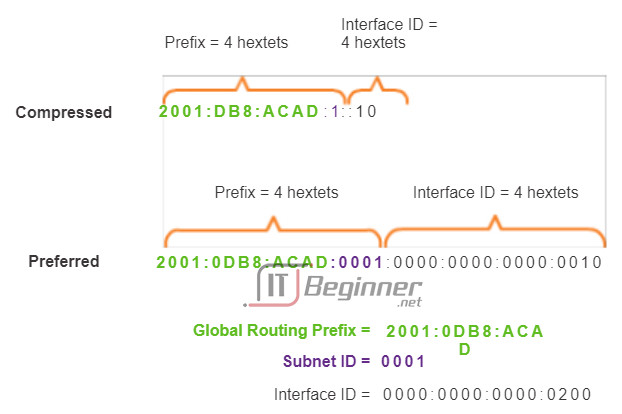
Interface ID
The IPv6 Interface ID is equivalent to the host portion of an IPv4 address. The term Interface ID is used because a single host may have multiple interfaces, each having one or more IPv6 addresses.
Note: Unlike IPv4, in IPv6, the all-0s address can be assigned to a device because there are no broadcast addresses in IPv6. However, the all-0s address is reserved as a Subnet-Router anycast address, and should be assigned only to routers.
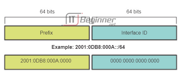
An easy way to read most IPv6 addresses is to count the number of hextets. As shown in Figure 3, in a /64 global unicast address the first four hextets are for the network portion of the address, with the fourth hextet indicating the Subnet ID. The remaining four hextets are for the Interface ID.
[tabs type=”horizontal”]
[tabs_head]
[tab_title]Figure 1[/tab_title]
[tab_title]Figure 2[/tab_title]
[tab_title]Figure 3[/tab_title]
[/tabs_head]
[tab]
[/tab]
[tab]
[/tab]
[tab]
[/tab]
[/tabs]
8.2.4.2 Static Configuration of a Global Unicast Address
Router Configuration
Most IPv6 configuration and verification commands in the Cisco IOS are similar to their IPv4 counterparts. In many cases the only difference is the use of ipv6 in place of ip within the commands.
The interface command to configure an IPv6 global unicast address on an interface is ipv6 address ipv6-address/prefix-length.
Notice that there is not a space between ipv6-address and prefix-length.
The example configuration will use the topology shown in Figure 1 and these IPv6 subnets:
- 2001:0DB8:ACAD:0001:/64 (or 2001:DB8:ACAD:1::/64)
- 2001:0DB8:ACAD:0002:/64 (or 2001:DB8:ACAD:2::/64)
- 2001:0DB8:ACAD:0003:/64 (or 2001:DB8:ACAD:3::/64)
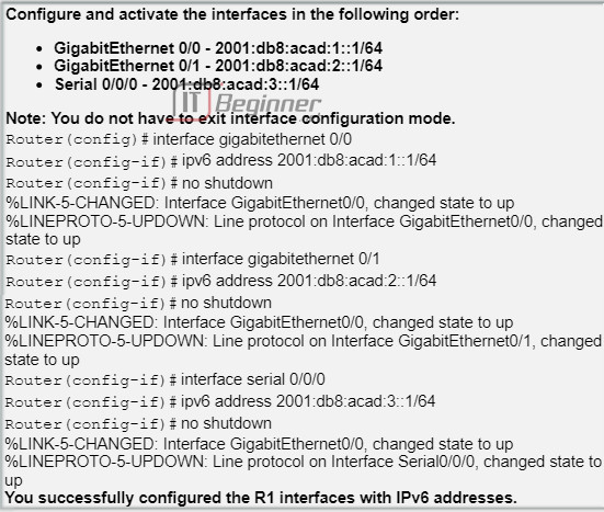
As shown in Figure 2, the commands required to configure the IPv6 global unicast address on the GigabitEthernet 0/0 interface of R1 would be:
Router(config)#interface GigabitEthernet 0/0
Router(config-if)#ipv6 address 2001:db8:acad:1::1/64
Router(config-if)#no shutdown
Host Configuration
Manually configuring the IPv6 address on a host is similar to configuring an IPv4 address.
As shown in Figure 3, the default gateway address configured for PC1 is 2001:DB8:ACAD:1::1, the global unicast address of the R1 GigabitEthernet interface on the same network.
Use the Syntax Checker in Figure 4 to configure the IPv6 global unicast address.
Just as with IPv4, configuring static addresses on clients does not scale to larger environments. For this reason, most network administrators in an IPv6 network will enable dynamic assignment of IPv6 addresses.
There are two ways in which a device can obtain an IPv6 global unicast address automatically:
- Stateless Address Autoconfiguration (SLAAC)
- DHCPv6
[tabs type=”horizontal”]
[tabs_head]
[tab_title]Figure 1[/tab_title]
[tab_title]Figure 2[/tab_title]
[tab_title]Figure 3[/tab_title]
[tab_title]Figure 4[/tab_title]
[/tabs_head]
[tab]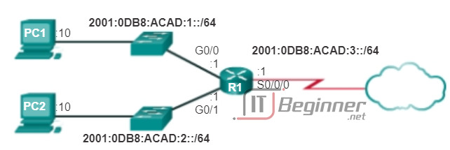 [/tab]
[tab]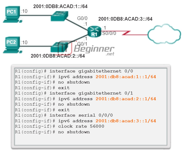 [/tab]
[tab]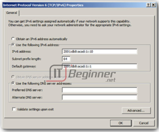 [/tab]
[tab]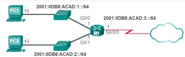
 [/tab]
[/tabs]
8.2.4.3 Dynamic Configuration of a Global Unicast Address using SLAAC
Stateless Address Autoconfiguration (SLAAC)
Stateless Address Autoconfiguration (SLAAC) is a method that allows a device to obtain its prefix, prefix length, and default gateway address information from an IPv6 router without the use of a DHCPv6 server. Using SLAAC, devices rely on the local router’s ICMPv6 Router Advertisement (RA) messages to obtain the necessary information.
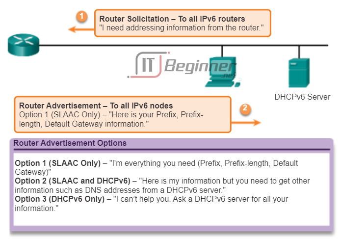
IPv6 routers periodically send out ICMPv6 Router Advertisement (RA) messages to all IPv6-enabled devices on the network. By default, Cisco routers send out RA messages every 200 seconds to the IPv6 all-nodes multicast group address. An IPv6 device on the network does not have to wait for these periodic RA messages. A device can send a Router Solicitation (RS) message to the router, using the IPv6 all-routers multicast group address. When an IPv6 router receives an RS message it will immediately respond with a router advertisement.
Even though an interface on a Cisco router can be configured with an IPv6 address, this does not make it an “IPv6 router”. An IPv6 router is a router that:
- Forwards IPv6 packets between networks
- Can be configured with static IPv6 routes or a dynamic IPv6 routing protocol
- Sends ICMPv6 RA messages
IPv6 routing is not enabled by default. To enable a router as an IPv6 router, the ipv6 unicast-routing global configuration command must be used.
Note: Cisco routers are enabled as IPv4 routers by default.
The ICMPv6 RA message contains the prefix, prefix length, and other information for the IPv6 device. The RA message also informs the IPv6 device how to obtain its addressing information. The RA message can contain one of the following three options, as shown in the figure:
- Option 1 – SLAAC Only – The device should use the prefix, prefix-length, and default gateway address information contained in the RA message. No other information is available from a DHCPv6 server.
- Option 2 – SLAAC and DHCPv6 – The device should use the prefix, prefix-length, and default gateway address information in the RA message. There is other information available from a DHCPv6 server such as the DNS server address. The device will, through the normal process of discovering and querying a DHCPv6 server, obtain this additional information. This is known as stateless DHCPv6 because the DHCPv6 server does not need to allocate or keep track of any IPv6 address assignments, but only provide additional information such as the DNS server address.
- Option 3 – DHCPv6 only – The device should not use the information in this RA message for its addressing information. Instead, the device will use the normal process of discovering and querying a DHCPv6 server to obtain all of its addressing information. This includes an IPv6 global unicast address, prefix length, a default gateway address, and the addresses of DNS servers. In this case, the DHCPv6 server is acting as a stateful DHCP server similar to DHCP for IPv4. The DHCPv6 server allocates and keeps track of IPv6 addresses so it does not assign the same IPv6 address to multiple devices.
Routers send ICMPv6 RA messages using the link-local address as the source IPv6 address. Devices using SLAAC use the router’s link-local address as their default gateway address.
8.2.4.4 Dynamic Configuration of a Global Unicast Address using DHCPv6
DHCPv6
Dynamic Host Configuration Protocol for IPv6 (DHCPv6) is similar to DHCP for IPv4. A device can automatically receive its addressing information including a global unicast address, prefix length, default gateway address and the addresses of DNS servers using the services of a DHCPv6 server.
A device may receive all or some of its IPv6 addressing information from a DHCPv6 server depending upon whether option 2 (SLAAC and DHCPv6) or option 3 (DHCPv6 only) is specified in the ICMPv6 RA message. Additionally, the host OS may choose to ignore whatever is in the router’s RA message and obtain its IPv6 address and other information directly from a DHCPv6 server.
Before deploying IPv6 devices in a network it is a good idea to first verify whether the host observes the options within the router’s ICMPv6 RA message.
A device may obtain its IPv6 global unicast address dynamically and also be configured with multiple static IPv6 addresses on the same interface. IPv6 allows for multiple IPv6 addresses, belonging to the same IPv6 network, to be configured on the same interface.
A device may also be configured with more than one default gateway IPv6 address. For further information about how the decision is made regarding which address is used as a source IPv6 address or which default gateway address is used, refer to RFC 6724, Default Address Selection for IPv6.
The Interface ID
If the client does not use the information contained within the RA message and relies solely on DHCPv6, then the DHCPv6 server will provide the entire IPv6 global unicast address, including the prefix and the Interface ID.
However, if option 1 (SLAAC only) or option 2 (SLAAC with DHCPv6) is used, the client does not obtain the actual Interface ID portion of the address from this processes. The client device must determine its own 64-bit Interface ID, either by using the EUI-64 process or by generating a random 64-bit number.
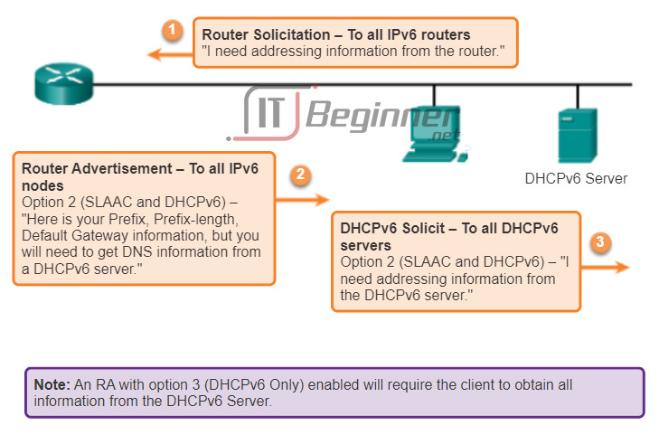
8.2.4.5 EUI-64 Process or Randomly Generated
EUI-64 Process
IEEE defined the Extended Unique Identifier (EUI) or modified EUI-64 process. This process uses a client’s 48-bit Ethernet MAC address, and inserts another 16 bits in the middle of the 48-bit MAC address to create a 64-bit Interface ID.
Ethernet MAC addresses are usually represented in hexadecimal and are made up of two parts:
- Organizationally Unique Identifier (OUI) – The OUI is a 24-bit (6 hexadecimal digits) vendor code assigned by IEEE.
- Device Identifier – The device identifier is a unique 24-bit (6 hexadecimal digits) value within a common OUI.
An EUI-64 Interface ID is represented in binary and is made up of three parts:
- 24-bit OUI from the client MAC address, but the 7th bit (the Universally/Locally (U/L) bit) is reversed. This means that if the 7th bit is a 0 it becomes a 1, and vice versa.
- The inserted 16-bit value FFFE (in hexadecimal)
- 24-bit Device Identifier from the client MAC address
The EUI-64 process is illustrated in Figure 1, using R1’s GigabitEthernet MAC address of FC99:4775:CEE0.
Step 1: Divide the MAC address between the OUI and device identifier.
Step 2: Insert the hexadecimal value FFFE, which in binary is: 1111 1111 1111 1110.
Step 3: Convert the first 2 hexadecimal values of the OUI to binary and flip the U/L bit (bit 7). In this example the 0 in bit 7 is changed to a 1.
The result is an EUI-64 generated Interface ID of FE99:47FF:FE75:CEE0.
Note: The use of the U/L bit and the reasons for reversing its value are discussed in RFC 5342.
The advantage of EUI-64 is the Ethernet MAC address can be used to determine the Interface ID. It also allows network administrators to easily track an IPv6 address to an end-device using the unique MAC address. However, this has caused privacy concerns among many users. They are concerned that their packets can be traced to the actual physical computer. Due to these concerns, a randomly generated Interface ID may be used instead.
Randomly Generated Interface IDs
Depending upon the operating system, a device may use a randomly generated Interface ID instead of using the MAC address and the EUI-64 process. For example, beginning with Windows Vista, Windows uses a randomly generated Interface ID instead of one created with EUI-64. Windows XP and previous Windows operating systems used EUI-64.
An easy way to identify that an address was more than likely created using EUI-64 is the FFFE located in the middle of the Interface ID, as shown in Figure 2.
After the Interface ID is established, either through the EUI-64 process or through random generation, it can be combined with an IPv6 prefix to create a global unicast address or a link-local address:
- Global unicast address – When using SLAAC, the device receives its prefix from the ICMPv6 RA and combines it with the Interface ID.
- Link-local address – A link-local prefix begins with FE80::/10. A device typically uses FE80::/64 as the prefix/prefix-length, followed by the Interface ID.
[tabs type=”horizontal”]
[tabs_head]
[tab_title]Figure 1[/tab_title]
[tab_title]Figure 2[/tab_title]
[/tabs_head]
[tab]
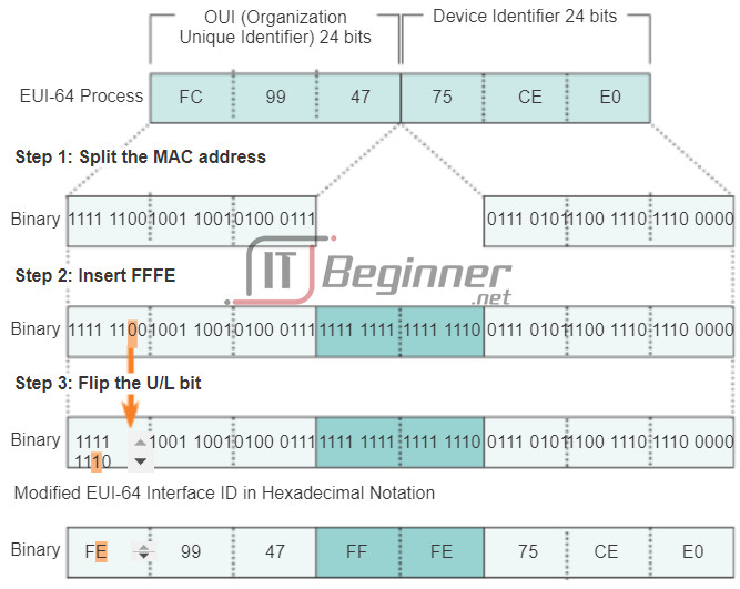
[/tab]
[tab]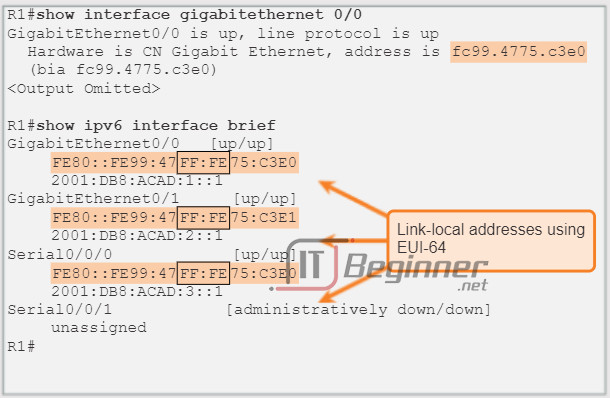 [/tab]
[/tabs]
8.2.4.6 Dynamic Link-local Addresses
When using SLAAC (SLAAC only or SLAAC with DHCPV6), a device receives its prefix and prefix length from the ICMPv6 RA. Because the prefix of the address has been designated by the RA message, the device must provide only the Interface ID portion of its address. As stated previously, the Interface ID can be automatically generated using the EUI-64 process, or depending on the OS, randomly generated. Using the information from the RA message and the Interface ID, the device can establish its global unicast address.
After a global unicast address is assigned to an interface, the IPv6-enabled device will automatically generate its link-local address. IPv6-enabled devices must have, at a minimum, the link-local address. Recall that an IPv6 link-local address enables a device to communicate with other IPv6-enabled devices on the same subnet.
IPv6 link-local addresses are used for a variety of purposes including:
- A host uses the link-local address of the local router for its default gateway IPv6 address.
- Routers exchange dynamic routing protocol messages using link-local addresses.
- Routers’ routing tables use the link-local address to identify the next-hop router when forwarding IPv6 packets.
A link-local address can be established dynamically or configured manually as a static link-local address.
Dynamically Assigned Link-Local Address
The link-local address is dynamically created using the FE80::/10 prefix and the Interface ID.
By default, Cisco IOS routers use EUI-64 to generate the Interface ID for all link-local address on IPv6 interfaces. For serial interfaces, the router will use the MAC address of an Ethernet interface. Recall that a link-local address must be unique only on that link or network. However, a drawback to using the dynamically assigned link-local address is its length, which makes it challenging to identify and remember assigned addresses.
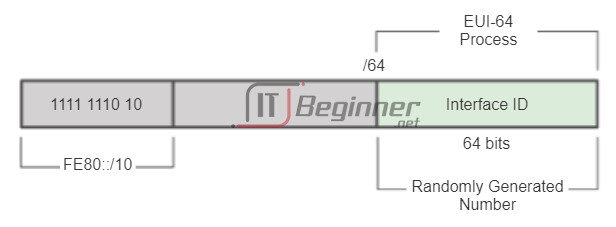
8.2.4.7 Static Link-Local Addresses
Static Link-Local Address
Configuring the link-local address manually provides the ability to create an address that is recognizable and easier to remember.
Link-local addresses can be configured manually using the same interface command used to create IPv6 global unicast addresses but with an additional parameter:
Router(config-if)#ipv6 address link-local-address link-local
Figure 1 shows that a link-local address has a prefix within the range FE80 to FEBF. When an address begins with this hextet (16-bit segment) the link-local parameter must follow the address.
Figure 2 shows the configuration of a link-local address using the ipv6 address interface command. The link-local address FE80::1 is used to make it easily recognizable as belonging to router R1. The same IPv6 link-local address is configured on all of R1’s interfaces. FE80::1 can be configured on each link because it only has to be unique on that link.
Similar to R1, router R2 would be configured with FE80::2 as the IPv6 link-local address on all of its interfaces
[tabs type=”horizontal”]
[tabs_head]
[tab_title]Figure 1[/tab_title]
[tab_title]Figure 2[/tab_title]
[/tabs_head]
[tab]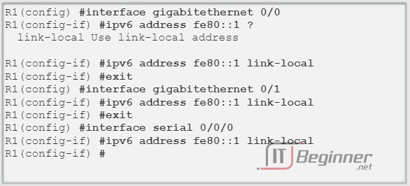 [/tab]
[tab]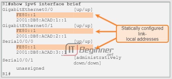 [/tab]
[/tabs]
8.2.4.8 Verifying IPv6 Address Configuration
As shown in Figure 1, the command to verify the IPv6 interface configuration is similar to the command used for IPv4.
The show interface command displays the MAC address of the Ethernet interfaces. EUI-64 uses this MAC address to generate the Interface ID for the link-local address. Additionally, the show ipv6 interface brief command displays abbreviated output for each of the interfaces. The [up/up] output on the same line as the interface indicates the Layer 1/Layer 2 interface state. This is the same as the Status and Protocol columns in the equivalent IPv4 command.
Notice that each interface has two IPv6 addresses. The second address for each interface is the global unicast address that was configured. The first address, the one that begins with FE80, is the link-local unicast address for the interface. Recall that the link-local address is automatically added to the interface when a global unicast address is assigned.
Also, notice that R1’s Serial 0/0/0 link-local address is the same as its GigabitEthernet 0/0 interface. Serial interfaces do not have an Ethernet MAC addresses so Cisco IOS uses the MAC address of the first available Ethernet interface. This is possible because link-local interfaces only have to be unique on that link.
The link-local address of the router interface is typically the default gateway address for devices on that link or network.
As shown in Figure 2, the show ipv6 route command can be used to verify that IPv6 networks and specific IPv6 interface addresses have been installed in the IPv6 routing table. The show ipv6 route command will only display IPv6 networks, not IPv4 networks.
Within the route table, a C next to a route indicates that this is a directly connected network. When the router interface is configured with a global unicast address and is in the “up/up” state, the IPv6 prefix and prefix length is added to the IPv6 routing table as a connected route.
The IPv6 global unicast address configured on the interface is also installed in the routing table as a local route. The local route has a /128 prefix. Local routes are used by the routing table to efficiently process packets with a destination address of the router’s interface address.
The ping command for IPv6 is identical to the command used with IPv4, except that an IPv6 address is used. As shown in Figure 3, the command is used to verify Layer 3 connectivity between R1 and PC1. When pinging a link-local address from a router, Cisco IOS will prompt the user for the exit interface. Because the destination link-local address can be on one or more of its links or networks, the router needs to know which interface to send the ping.
Use the Syntax Checker in Figure 4 to verify IPv6 address configuration.
[tabs type=”horizontal”]
[tabs_head]
[tab_title]Figure 1[/tab_title]
[tab_title]Figure 2[/tab_title]
[tab_title]Figure 3[/tab_title]
[/tabs_head]
[tab]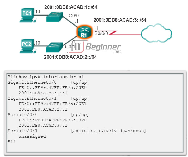 [/tab]
[tab]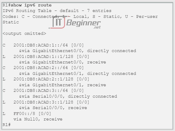 [/tab]
[tab] [/tab]
[/tabs]
8.2.5 IPv6 Multicast Addresses
8.2.5.1 Assigned IPv6 Multicast Addresses
IPv6 multicast addresses are similar to IPv4 multicast addresses. Recall that a multicast address is used to send a single packet to one or more destinations (multicast group). IPv6 multicast addresses have the prefix FF00::/8.
Note: Multicast addresses can only be destination addresses and not source addresses.
There are two types of IPv6 multicast addresses:
- Assigned multicast
- Solicited node multicast
Assigned Multicast
Assigned multicast addresses are reserved multicast addresses for predefined groups of devices. An assigned multicast address is a single address used to reach a group of devices running a common protocol or service. Assigned multicast addresses are used in context with specific protocols such as DHCPv6.
Two common IPv6 assigned multicast groups include:
- FF02::1 All-nodes multicast group – This is a multicast group that all IPv6-enabled devices join. A packet sent to this group is received and processed by all IPv6 interfaces on the link or network. This has the same effect as a broadcast address in IPv4. The figure shows an example of communication using the all-nodes multicast address. An IPv6 router sends Internet Control Message Protocol version 6 (ICMPv6) RA messages to the all-node multicast group. The RA message informs all IPv6-enabled devices on the network about addressing information, such as the prefix, prefix length, and default gateway.
- FF02::2 All-routers multicast group – This is a multicast group that all IPv6 routers join. A router becomes a member of this group when it is enabled as an IPv6 router with the ipv6 unicast-routing global configuration command. A packet sent to this group is received and processed by all IPv6 routers on the link or network.
IPv6-enabled devices send ICMPv6 Router Solicitation (RS) messages to the all-routers multicast address. The RS message requests an RA message from the IPv6 router to assist the device in its address configuration.
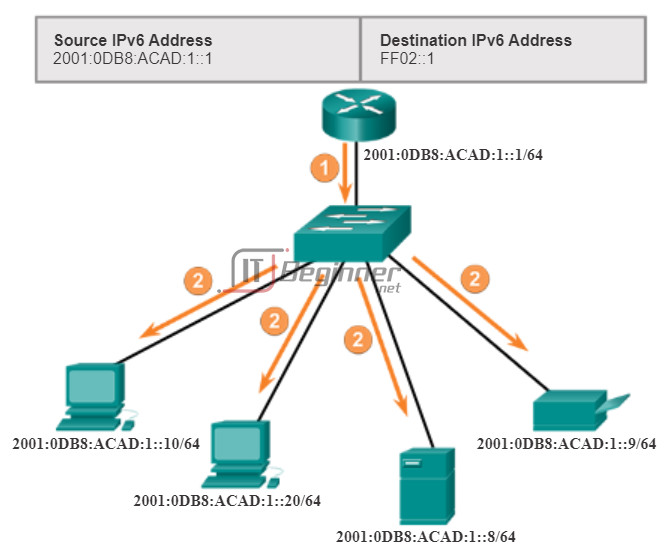
8.2.5.2 Solicited-Node IPv6 Multicast Addresses
A solicited-node multicast is similar to the all-nodes multicast address. Recall that the all-nodes multicast address is essentially the same thing as an IPv4 broadcast. All devices on the network must process traffic sent to the all-nodes address. To reduce the number of devices that must process traffic, use a solicited-node multicast address.
A solicited-node multicast address is an address that matches only the last 24 bits of the IPv6 global unicast address of a device. The only devices that need to process these packets are those devices that have these same 24 bits in the least significant, far right portion of their Interface ID.
An IPv6 solicited-node multicast address is automatically created when the global unicast or link-local unicast addresses are assigned. The IPv6 solicited-node multicast address is created by combining a special FF02:0:0:0:0:FF00::/104 prefix with the far right 24 bits of its unicast address.
The solicited-node multicast address consists of two parts:
- FF02:0:0:0:0:FF00::/104 multicast prefix – This is the first 104 bits of the all solicited-node multicast address.
- Least significant 24-bits – These are the last or far right 24 bits of the solicited-node multicast address. These bits are copied from the far right 24 bits of the global unicast or link-local unicast address of the device.
It is possible that multiple devices will have the same solicited-node multicast address. Although rare, this can occur when devices have the same far right 24 bits in their Interface IDs. This does not create any problems because the device will still process the encapsulated message, which will include the complete IPv6 address of the device in question.
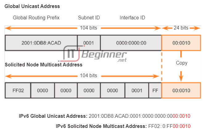
8.2.5.3 Packet Tracer – Configuring IPv6 Addressing
In this activity, you will practice configuring IPv6 addresses on a router, servers, and clients. You will also practice verifying your IPv6 addressing implementation.
Packet Tracer – Configuring IPv6 Addressing Instructions ./.
Packet Tracer – Configuring IPv6 Addressing – PKA ./.
8.2.5.4 Lab – Identifying IPv6 Addresses
In this lab, you will complete the following objectives:
- Part 1: Identify the Different Types of IPv6 Addresses
- Part 2: Examine a Host IPv6 Network Interface and Address
- Part 3: Practice IPv6 Address Abbreviation
- Part 4: Identify the Hierarchy of the IPv6 Global Unicast Address Network Prefix
Lab – Identifying IPv6 Addresses ./.
8.2.5.5 Lab – Configuring IPv6 Addresses on Network Devices
In this lab, you will complete the following objectives:
- Part 1: Set Up Topology and Configure Basic Router and Switch Settings
- Part 2: Configure IPv6 Addresses Manually
- Part 3: Verify End-to-End Connectivity
Lab – Configuring IPv6 Addresses on Network Devices ./.
8.3 Connectivity Verification
8.3.1 ICMP
8.3.1.1 ICMPv4 and ICMPv6 Messages
Although IP is not a reliable protocol, the TCP/IP suite does provide for messages to be sent in the event of certain errors. These messages are sent using the services of ICMP. The purpose of these messages is to provide feedback about issues related to the processing of IP packets under certain conditions, not to make IP reliable. ICMP messages are not required and are often not allowed within a network for security reasons.
ICMP is available for both IPv4 and IPv6. ICMPv4 is the messaging protocol for IPv4. ICMPv6 provides these same services for IPv6 but includes additional functionality. In this course, the term ICMP will be used when referring to both ICMPv4 and ICMPv6.
The types of ICMP messages, and the reasons why they are sent, are extensive. We will discuss some of the more common messages.
ICMP messages common to both ICMPv4 and ICMPv6 include:
- Host confirmation
- Destination or Service Unreachable
- Time exceeded
- Route redirection
Host Confirmation
An ICMP Echo Message can be used to determine if a host is operational. The local host sends an ICMP Echo Request to a host. If the host is available, the destination host responds with an Echo Reply. In the figure, click the Play button to see an animation the ICMP Echo Request/Echo Reply. This use of the ICMP Echo messages is the basis of the ping utility.
Destination or Service Unreachable
When a host or gateway receives a packet that it cannot deliver, it can use an ICMP Destination Unreachable message to notify the source that the destination or service is unreachable. The message will include a code that indicates why the packet could not be delivered.
Some of the Destination Unreachable codes for ICMPv4 are:
- 0 – net unreachable.
- 1 – host unreachable.
- 2 – protocol unreachable.
- 3 – port unreachable.
Note: ICMPv6 has similar but slightly different codes for Destination Unreachable messages.
Time Exceeded
An ICMPv4 Time Exceeded message is used by a router to indicate that a packet cannot be forwarded because the Time to Live (TTL) field of the packet was decremented to 0. If a router receives a packet and decrements the TTL field in the IPv4 packet to zero, it discards the packet and sends a Time Exceeded message to the source host.
ICMPv6 also sends a Time Exceeded message if the router cannot forward an IPv6 packet because the packet has expired. IPv6 does not have a TTL field; it uses the hop limit field to determine if the packet has expired.
Route Redirection
A router may use the ICMP Redirect Message to notify the hosts on a network that a better route is available for a particular destination. This message may only be used when the source host is on the same physical network as both gateways.
Both ICMPv4 and ICMPv6 use route redirection messages.
8.3.1.2 ICMPv6 Router Solicitation and Router Advertisement Messages
The informational and error messages found in ICMPv6 are very similar to the control and error messages implemented by ICMPv4. However, ICMPv6 has new features and improved functionality not found in ICMPv4.
ICMPv6 includes four new protocols as part of the Neighbor Discovery Protocol (ND or NDP):
- Router Solicitation message
- Router Advertisement message
- Neighbor Solicitation message
- Neighbor Advertisement message
Router Solicitation and Router Advertisement Messages
IPv6-enabled devices can be divided into two categories, routers and hosts. Router Solicitation and Router Advertisement messages are sent between hosts and routers.
- Router Solicitation (RS) message: When a host is configured to obtain its addressing information automatically using Stateless Address Autoconfiguration (SLAAC), the host will send an RS message to the router. The RS message is sent as an IPv6 all-routers multicast message.
- Router Advertisement (RA) message: RA messages are sent by routers to provide addressing information to hosts using SLAAC. The RA message can include addressing information for the host such as the prefix and prefix length. A router will send an RA message periodically or in response to an RS message. By default, Cisco routers send RA messages every 200 seconds. RA messages are sent to the IPv6 all-nodes multicast address. A host using SLAAC will set its default gateway to the link-local address of the router that sent the RA.
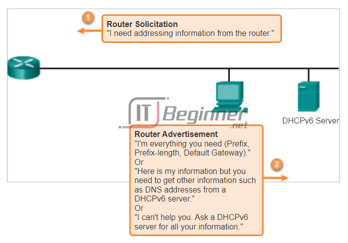
8.3.1.3 ICMPv6 Neighbor Solicitation and Neighbor Advertisement Messages
ICMPv6 Neighbor Discovery Protocol includes two additional message types, Neighbor Solicitation (NS) and Neighbor Advertisement (NA) messages.
Neighbor Solicitation and Neighbor Advertisement messages are used for:
- Address resolution
- Duplicate Address Detection (DAD)
Address Resolution
Address resolution is used when a device on the LAN knows the IPv6 unicast address of a destination but does not know its Ethernet MAC address. To determine the MAC address for the destination, the device will send an NS message to the solicited node address. The message will include the known (targeted) IPv6 address. The device that has the targeted IPv6 address will respond with a NA message containing its Ethernet MAC address.
Duplicate Address Detection
When a device is assigned a global unicast or link-local unicast address, it is recommended DAD is performed on the address to ensure that it is unique. To check the uniqueness of an address, the device will send a NS message with its own IPv6 address as the targeted IPv6 address. If another device on the network has this address it will respond with a NA message. This NA message will notify the sending device that the address is in use. If a corresponding NA message is not returned within a certain period of time, the unicast address is unique and acceptable for use.
Note: DAD is not required, but RFC 4861 recommends that DAD is performed on unicast addresses.
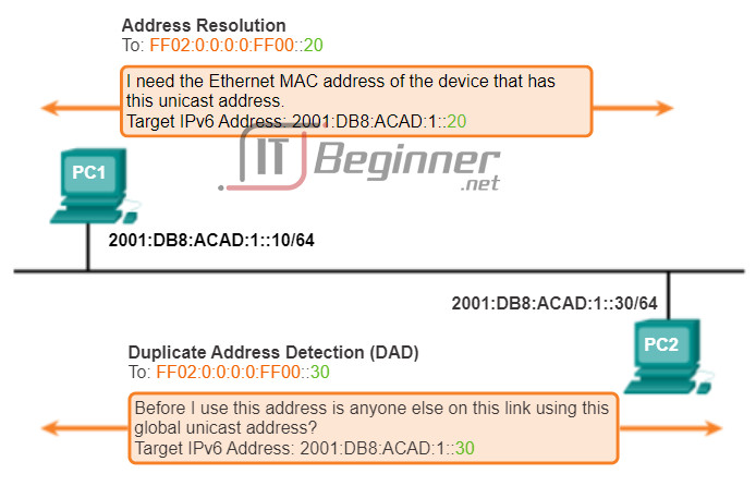
8.3.2 Testing and Verification
8.3.2.1 Ping – Testing the Local Stack
Ping is a testing utility that uses ICMP echo request and echo reply messages to test connectivity between hosts. Ping works with both IPv4 and IPv6 hosts.
To test connectivity to another host on a network, an echo request is sent to the host address using the ping command. If the host at the specified address receives the echo request, it responds with an echo reply. As each echo reply is received, ping provides feedback on the time between when the request was sent and when the reply was received. This can be a measure of network performance.
Ping has a timeout value for the reply. If a reply is not received within the timeout, ping provides a message indicating that a response was not received. This usually indicates that there is a problem, but could also indicate that security features blocking ping messages have been enabled on the network.
After all the requests are sent, the ping utility provides a summary that includes the success rate and average round-trip time to the destination.
Pinging the Local Loopback
There are some special testing and verification cases for which we can use ping. One case is for testing the internal configuration of IPv4 or IPv6 on the local host. To perform this test, we ping the local loopback address of 127.0.0.1 for IPv4 (::1 for IPv6). Testing the IPv4 loopback is shown in the figure.
A response from 127.0.0.1 for IPv4, or ::1 for IPv6, indicates that IP is properly installed on the host. This response comes from the network layer. This response is not, however, an indication that the addresses, masks, or gateways are properly configured. Nor does it indicate anything about the status of the lower layer of the network stack. This simply tests IP down through the network layer of IP. If we get an error message, it is an indication that TCP/IP is not operational on the host.
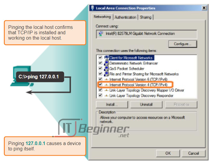
8.3.2.2 Ping – Testing Connectivity to the Local LAN
You can also use ping to test the ability of a host to communicate on the local network. This is generally done by pinging the IP address of the gateway of the host. A ping to the gateway indicates that the host and the router interface serving as the gateway are both operational on the local network.
For this test, the gateway address is most often used, because the router is normally always operational. If the gateway address does not respond, a ping can be sent to the IP address of another host on the local network that is known to be operational.
If either the gateway or another host responds, then the local host can successfully communicate over the local network. If the gateway does not respond but another host does, this could indicate a problem with the router interface serving as the gateway.
One possibility is that the wrong gateway address has been configured on the host. Another possibility is that the router interface may be fully operational but have security applied to it that prevents it from processing or responding to ping requests.
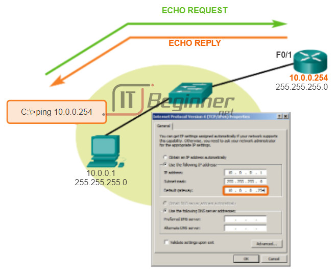
8.3.2.3 Ping – Testing Connectivity to Remote
Ping can also be used to test the ability of a local host to communicate across an internetwork. The local host can ping an operational IPv4 host of a remote network, as shown in the figure.
If this ping is successful, the operation of a large piece of the internetwork can be verified. A successful ping across the internetwork confirms communication on the local network, the operation of the router serving as our gateway, and the operation of all other routers that might be in the path between the local network and the network of the remote host.
Additionally, functionality of the remote host can be verified. If the remote host could not communicate outside of its local network, it would not have responded.
Note: Many network administrators limit or prohibit the entry of ICMP messages into the corporate network; therefore, the lack of a ping response could be due to security restrictions.
Ping to a Remote Host
8.3.2.4 Traceroute – Testing the Path
Ping is used to test connectivity between two hosts, but doesn’t provide information about the details of devices between the hosts. Traceroute (tracert) is a utility generates a list of hops that were successfully reached along the path. This list can provide important verification and troubleshooting information. If the data reaches the destination, then the trace lists the interface of every router in the path between the hosts. If the data fails at some hop along the way, the address of the last router that responded to the trace can provide an indication of where the problem or security restrictions are found.
Round Trip Time (RTT)
Using traceroute provides round trip time for each hop along the path and indicates if a hop fails to respond. The round trip time is the time a packet takes to reach the remote host and for the response from the host to return. An asterisk (*) is used to indicate a lost or unreplied packet.
This information can be used to locate a problematic router in the path. If the display shows high response times or data losses from a particular hop, this is an indication that the resources of the router or its connections may be stressed.
IPv4 Time-to-Live (TTL) and IPv6 Hop Limit
Traceroute makes use of a function of the TTL field in IPv4 and the Hop Limit field in IPv6 in the Layer 3 headers, along with the ICMP time exceeded message.
Play the animation in the figure to see how Traceroute takes advantage of TTL.
The first sequence of messages sent from traceroute will have a TTL field value of 1. This causes the TTL to time out the IPv4 packet at the first router. This router then responds with an ICMPv4 message. Traceroute now has the address of the first hop.
Traceroute then progressively increments the TTL field (2, 3, 4…) for each sequence of messages. This provides the trace with the address of each hop as the packets timeout further down the path. The TTL field continues to be increased until the destination is reached or it is incremented to a predefined maximum.
Once the final destination is reached, the host responds with either an ICMP port unreachable message or an ICMP echo reply message instead of the ICMP time exceeded message.
8.3.2.5 Packet Tracer – Verifying IPv4 and IPv6 Addressing
IPv4 and IPv6 can coexist on the same network. From the command prompt of a PC there are some differences in the way commands are issued and in the way output is displayed.
Packet Tracer – Verifying IPv4 and IPv6 Addressing Instructions ./.
Packet Tracer – Verifying IPv4 and IPv6 Addressing – PKA ./.
8.3.2.6 Packet Tracer – Pinging and Tracing to Test the Path
There are connectivity issues in this activity. In addition to gathering and documenting information about the network, you will locate the problems and implement acceptable solutions to restore connectivity.
Packet Tracer – Pinging and Tracing to Test the Path Instructions ./.
Packet Tracer – Pinging and Tracing to Test the Path – PKA ./.
8.3.2.7 Lab – Testing Network Connectivity with Ping and Traceroute
In this lab, you will complete the following objectives:
- Part 1: Build and Configure the Network
- Part 2: Use Ping Command for Basic Network Testing
- Part 3: Use Tracert and Traceroute Commands for Basic Network Testing
- Part 4: Troubleshoot the Topology
Lab – Testing Network Connectivity with Ping and Traceroute ./.
8.3.2.8 Packet Tracer – Troubleshooting IPv4 and IPv6 Addressing
You are a network technician working for a company that has decided to migrate from IPv4 to IPv6. In the interim, they must support both protocols (dual stack). Three co-workers have called the help desk with problems and have received limited assistance. The help desk has escalated the matter to you, a Level 2 support technician.
Packet Tracer – Troubleshooting IPv4 and IPv6 Addressing Instructions ./.
Packet Tracer – Troubleshooting IPv4 and IPv6 Addressing – PKA ./.
8.4 Summary
8.4.1 Summary
8.4.1.1 Class Activity – The Internet of Everything…Naturally!
In this chapter, you learned about how small to medium-sized businesses are connected to networks in groups. The Internet of Everything was also introduced in the beginning modeling activity.
For this activity, choose one of the following:
- Online banking
- World news
- Weather forecasting/climate
- Traffic conditions
Devise an IPv6 addressing scheme for the area you chose. Include in your addressing scheme how you would plan for:
- Subnetting
- Unicasts
- Multicasts
- Broadcasts
Keep a copy of your scheme to share with the class or learning community. Be prepared to explain:
- How subnetting, unicasts, multicasts and broadcasts would be incorporated.
- Where your addressing scheme could be used.
- How small to medium-size businesses would be impacted by using your plan.
Class Activity – The Internet of Everything…Naturally Instructions ./.

8.4.1.2 Packet Tracer – Skills Integration Challenge
Your company has won a contract to set up a small network for a restaurant owner. There are two restaurants near each other, and they all share one connection. The equipment and cabling is installed and the network administrator has designed the implementation plan. You job is implement the rest of the addressing scheme according to the abbreviated Addressing Table and verify connectivity.
Packet Tracer – Skills Integration Challenge Instructions ./.
Packet Tracer – Skills Integration Challenge – PKA ./.
8.4.1.3 Summary
IP addresses are hierarchical with network, subnetwork, and host portions. An IP address can represent a complete network, a specific host, or the broadcast address of the network.
Understanding binary notation is important when determining if two hosts are in the same network. The bits within the network portion of the IP address must be identical for all devices that reside in the same network. The subnet mask or prefix is used to determine the network portion of an IP address. IP addresses can be assigned either statically or dynamically. DHCP enables the automatic assignment of addressing information such as IP address, subnet mask, default gateway, and other configuration information.
IPv4 hosts can communicate one of three different ways: unicast, broadcast, and multicast. Also, blocks of addresses that are used in networks that require limited or no Internet access are called private addresses. The private IPv4 address blocks are: 10.0.0.0/8, 172.16.0.0/12, and 192.168.0.0/16.
The depletion of IPv4 address space is the motivating factor for moving to IPv6. Each IPv6 address has 128 bits verses the 32 bits in an IPv4 address. IPv6 does not use the dotted-decimal subnet mask notation. The prefix length is used to indicate the network portion of an IPv6 address using the following format: IPv6 address/prefix length.
There are three types of IPv6 addresses: unicast, multicast, and anycast. An IPv6 link-local address enables a device to communicate with other IPv6-enabled devices on the same link and only on that link (subnet). Packets with a source or destination link-local address cannot be routed beyond the link from where the packet originated. IPv6 link-local addresses are in the FE80::/10 range.
ICMP is available for both IPv4 and IPv6. ICMPv4 is the messaging protocol for IPv4. ICMPv6 provides the same services for IPv6 but includes additional functionality.
After it is implemented, an IP network needs to be tested to verify its connectivity and operational performance.