Introduction to Networks Instructor Materials – Chapter 7: Transport Layer
7.0 Transportation Layer
7.0.1 Introduction
7.0.1.1 Introduction
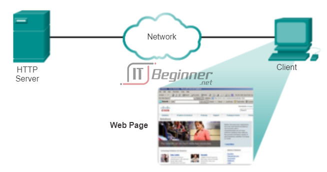
Data networks and the Internet support the human network by supplying reliable communication between people. On a single device, people can use multiple applications and services such as email, the web, and instant messaging to send messages or retrieve information. Applications such as email clients, web browsers, and instant messaging clients allow people to use computers and networks to send messages and find information.
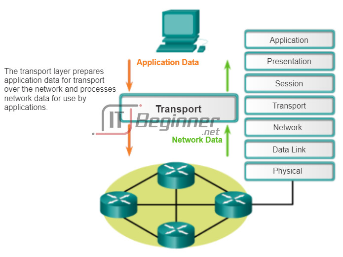
Data from each of these applications is packaged, transported, and delivered to the appropriate application on the destination device. The processes described in the OSI transport layer accept data from the application layer and prepare it for addressing at the network layer. The transport layer prepares data for transmission across the network. A source computer communicates with a receiving computer to decide how to break up data into segments, how to make sure none of the segments get lost, and how to verify all the segments arrived. When thinking about the transport layer, think of a shipping department preparing a single order of multiple packages for delivery.
In this chapter, we examine the role of the transport layer in encapsulating application data for use by the network layer. The transport layer also encompasses these functions:
- Enables multiple applications such as emailing and social networking to communicate over the network at the same time on a single device
- Ensures that, if required, all the data is received reliably and in order by the correct application
- Employs error handling mechanisms
Learning Objectives
Upon completion of this chapter, you will be able to:
- Explain the need for the transport layer.
- Identify the role of the transport layer as it provides the end-to-end transfer of data between applications.
- Describe the role of two TCP/IP transport layer protocols: TCP and UDP.
- Explain the key functions of the transport layer, including reliability, port addressing, and segmentation.
- Explain how TCP and UDP each handle key functions.
- Identify when it is appropriate to use TCP or UDP and provide examples of applications that use each protocol.
Upon completion of this chapter you will be able to:
- Describe the purpose of the transport layer in managing the transportation of data in end-to-end communication.
- Describe characteristics of the TCP and UDP protocols, including port numbers and their uses.
- Explain how TCP session establishment and termination processes facilitate reliable communication.
- Explain how TCP protocol data units are transmitted and acknowledged to guarantee delivery.
- Describe the UDP client processes to establish communication with a server.
- Determine whether high-reliability TCP transmissions, or non-guaranteed UDP transmissions, are best suited for common applications.
7.0.1.2 Class Activity – We Need to Talk – Game
Note: This activity works best with medium-sized groups of 6 to 8 students per group.
The instructor will whisper a complex message to the first student in a group. An example of the message might be “Our final exam will be given next Tuesday, February 5th, at 2 p.m. in Room 1151.”
That student whispers the message to the next student in the group. Each group follows this process until all members of each group have heard the whispered message. Here are the rules you are to follow:
- You can whisper the message only once to your neighbor.
- The message must keep moving from one person to the other with no skipping of participants.
- The instructor should ask a student to keep time of the full message activity from first participant to last participant stating the messages. The first or last person would mostly likely be the best one to keep this time.
- The last student will say aloud exactly what he or she heard.
The instructor will then restate the original message so that the group can compare it to the message that was delivered by the last student in the group.
Class Activity – We Need to Talk Instructions ./.
While completing this activity, think about how:
- Network communications have different levels of importance
- Important data must be accurate when sent and received
- Timing can be a factor when choosing a data delivery method
7.1 Transport Layer Protocols
7.1.1 Transportation of Data
7.1.1.1 Role of the Transport Layer
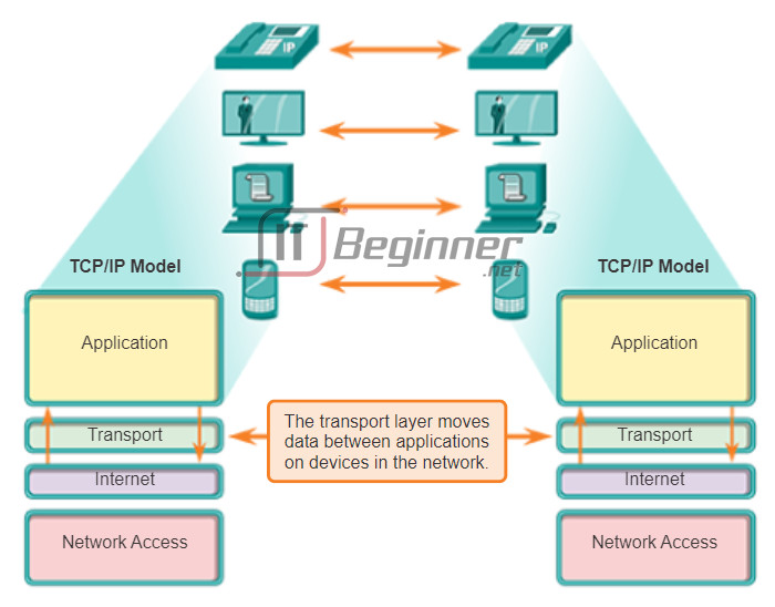
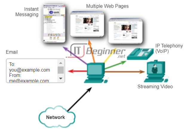
The transport layer is responsible for establishing a temporary communication session between two applications and delivering data between them. An application generates data that is sent from an application on a source host to an application on a destination host, without regard to the destination host type, the type of media over which the data must travel, the path taken by the data, the congestion on a link, or the size of the network. As shown in the figure, the transport layer is the link between the application layer and the lower layers that are responsible for network transmission.
The transport layer provides a method of delivering data across the network in a way that ensures the data can be properly put back together on the receiving end. The transport layer provides for the segmentation of data, and the controls necessary to reassemble these segments into the various communication streams. In TCP/IP, these segmentation and reassembly processes can be achieved using two very different transport layer protocols: Transmission Control Protocol (TCP) and User Datagram Protocol (UDP).
The primary responsibilities of transport layer protocols are:
- Tracking the individual communication between applications on the source and destination hosts
- Segmenting data for manageability and reassembling segmented data into streams of application data at the destination
- Identifying the proper application for each communication stream
7.1.1.2 Role of the Transport Layer (Cont.)
Tracking Individual Conversations
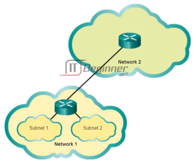
At the transport layer, each particular set of data flowing between a source application and a destination application is known as a conversation (Figure 1). A host may have multiple applications that are communicating across the network simultaneously. Each of these applications communicates with one or more applications on one or more remote hosts. It is the responsibility of the transport layer to maintain and track these multiple conversations.
Segmenting Data and Reassembling Segments
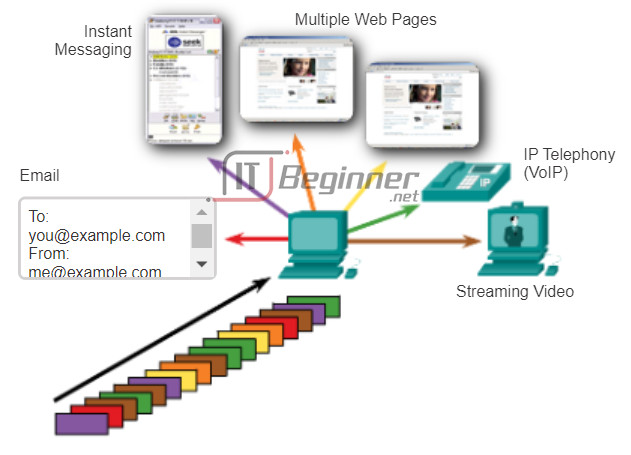
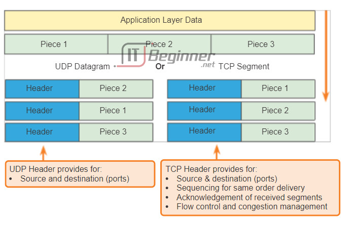
Data must be prepared to be sent across the media in manageable pieces. Most networks have a limitation on the amount of data that can be included in a single packet. Transport layer protocols have services that segment the application data into blocks of data that are an appropriate size (Figure 2). This service includes the encapsulation required on each piece of data. A header, used for reassembly, is added to each block of data. This header is used to track the data stream.
At the destination, the transport layer must be able to reconstruct the pieces of data into a complete data stream that is useful to the application layer. The protocols at the transport layer describe how the transport layer header information is used to reassemble the data pieces into streams to be passed to the application layer.
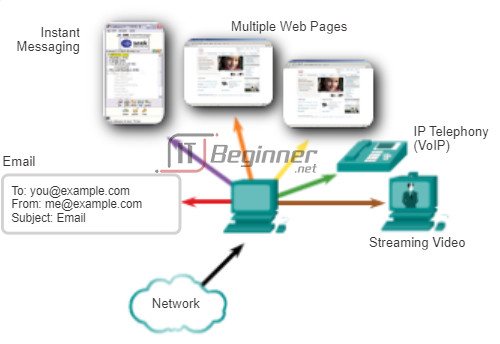
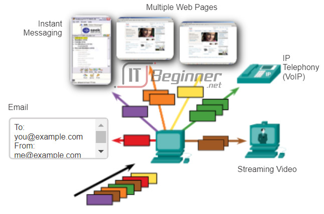
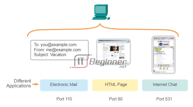
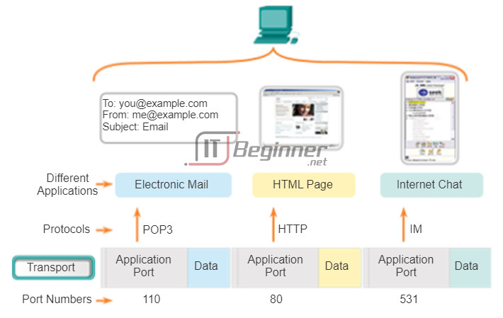
Identifying the Applications
There may be many applications or services running on each host in the network. To pass data streams to the proper applications, the transport layer must identify the target application (Figure 3). To accomplish this, the transport layer assigns each application an identifier. This identifier is called a port number. Each software process that needs to access the network is assigned a port number unique in that host. The transport layer uses ports to identify the application or service.
[tabs type=”horizontal”]
[tabs_head]
[tab_title]Tracking the Conversations[/tab_title]
[tab_title]Segmentation[/tab_title]
[tab_title]Identifying the Application[/tab_title]
[/tabs_head]
[tab]
[/tab]
[tab]
[/tab]
[tab]
[/tab]
[/tabs]
7.1.1.3 Conversation Multiplexing
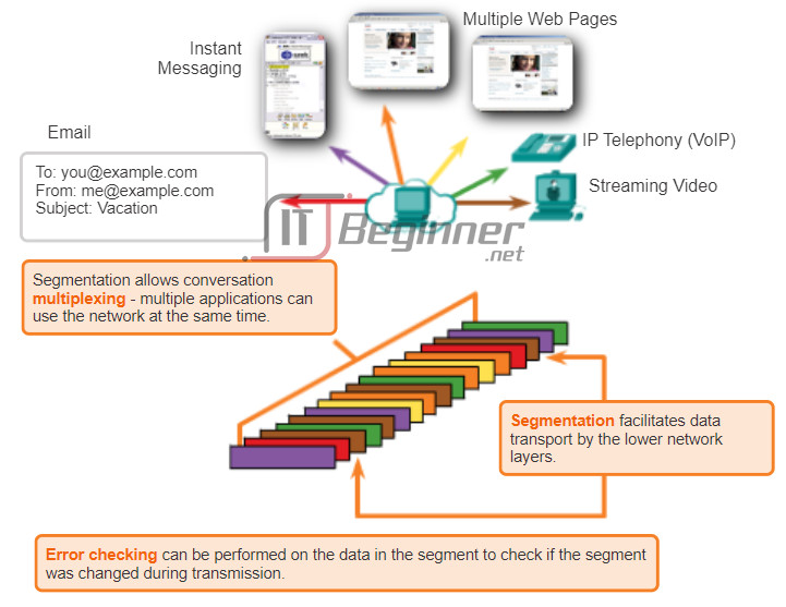
Sending some types of data (for example, a streaming video) across a network, as one complete communication stream, could use all of the available bandwidth and prevent other communications from occurring at the same time. It also makes error recovery and retransmission of damaged data difficult.
The figure shows that segmenting the data into smaller chunks enables many different communications, from many different users, to be interleaved (multiplexed) on the same network. Segmentation of the data by transport layer protocols also provides the means to both send and receive data when running multiple applications concurrently on a computer.
Without segmentation, only one application would be able to receive data. For example, a streaming video, the media would be completely consumed by the one communication stream instead of shared. You could not receive emails, chat on instant messenger, or view web pages while also viewing the video.
To identify each segment of data, the transport layer adds to the segment a header containing binary data. This header contains fields of bits. It is the values in these fields that enable different transport layer protocols to perform different functions in managing data communication.
7.1.1.4 Transport Layer Reliability
The transport layer is also responsible for managing reliability requirements of a conversation. Different applications have different transport reliability requirements.
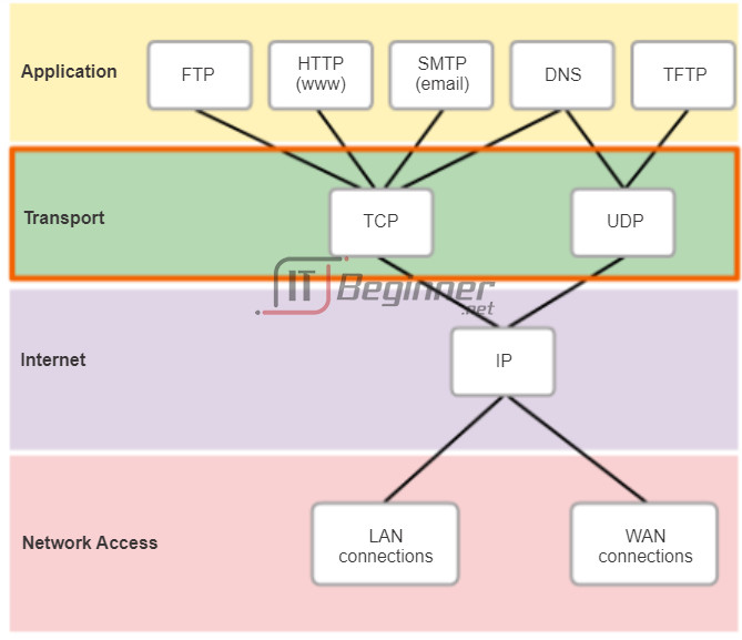
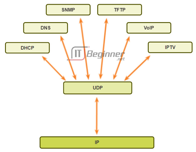
IP is concerned only with the structure, addressing, and routing of packets. IP does not specify how the delivery or transportation of the packets takes place. Transport protocols specify how to transfer messages between hosts. TCP/IP provides two transport layer protocols, Transmission Control Protocol (TCP) and User Datagram Protocol (UDP), as shown in the figure. IP uses these transport protocols to enable hosts to communicate and transfer data.
TCP is considered a reliable, full-featured transport layer protocol, which ensures that all of the data arrives at the destination. In contrast, UDP is a very simple transport layer protocol that does not provide for any reliability.
7.1.1.5 TCP
As previously stated, TCP is considered a reliable transport protocol, which means that TCP includes processes to ensure reliable delivery between applications through the use of acknowledged delivery. TCP transport is analogous to sending packages that are tracked from source to destination. If a FedEx order is broken up into several shipments, a customer can check online to see the order of the delivery.
With TCP, the three basic operations of reliability are:
- Tracking transmitted data segments
- Acknowledging received data
- Retransmitting any unacknowledged data
TCP breaks up a message into small pieces known as segments. The segments are numbered in sequence and passed to the IP process for assembly into packets. TCP keeps track of the number of segments that have been sent to a specific host from a specific application. If the sender does not receive an acknowledgement within a certain period of time, it assumes that the segments were lost and retransmits them. Only the portion of the message that is lost is resent, not the entire message. On the receiving host, TCP is responsible for reassembling the message segments and passing them to the application. The File Transfer Protocol (FTP) and the Hypertext Transfer Protocol (HTTP) are examples of applications that use TCP to ensure data delivery.
Click the Play button in the figure to see an animation of TCP segments being transmitted from sender to receiver.
These reliability processes place additional overhead on network resources due to the processes of acknowledgement, tracking, and retransmission. To support these reliability processes, more control data is exchanged between the sending and receiving hosts. This control information is contained in a TCP header.
7.1.1.6 UDP
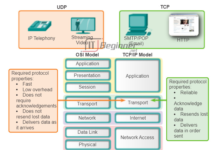
While the TCP reliability functions provide more robust communication between applications, they also incur additional overhead and possible delays in transmission. There is a trade-off between the value of reliability and the burden it places on network resources. Imposing overhead to ensure reliability for some applications could reduce the usefulness of the application and can even be detrimental to the application. In such cases, UDP is a better transport protocol.
UDP provides just the basic functions for delivering data segments between the appropriate applications, with very little overhead and data checking. UDP is known as a best-effort delivery protocol. In the context of networking, best-effort delivery is referred to as unreliable, because there is no acknowledgement that the data is received at the destination. With UDP, there are no transport layer processes that inform the sender if successful delivery has occurred.
UDP is similar to placing a regular, non-registered, letter in the mail. The sender of the letter is not aware of whether a receiver is available to receive the letter, nor is the post office responsible for tracking the letter or informing the sender if the letter does not arrive at the final destination.
Click the Play button in the figure to see an animation of UDP segments being transmitted from sender to receiver.
7.1.1.7 The Right Transport Layer Protocol for the Right Application
Both TCP and UDP are valid transport protocols. Depending upon the application requirements, either one, or sometimes both, of these transport protocols can be used. Application developers must choose which transport protocol type is appropriate based on the requirements of the applications.
For some applications, segments must arrive in a very specific sequence to be processed successfully. With other applications, all data must be fully received before any of it is considered useful. In both of these instances, TCP is used as the transport protocol. For example, applications such as databases, web browsers, and email clients, require that all data that is sent arrives at the destination in its original condition. Any missing data could cause a corrupt communication that is either incomplete or unreadable. Therefore, these applications are designed to use TCP. The additional network overhead is considered to be required for these applications.
In other cases, an application can tolerate some data loss during transmission over the network, but delays in transmission are unacceptable. UDP is the better choice for these applications because less network overhead is required. UDP is preferable with applications, such as streaming audio, video, and Voice over IP (VoIP). Acknowledgments would slow down delivery and retransmissions are undesirable.
For example, if one or two segments of a video stream fail to arrive, it creates a momentary disruption in the stream. This may appear as distortion in the image, but may not even be noticeable to the user. On the other hand, the image in a streaming video would be greatly degraded if the destination device had to account for lost data and delay the stream while waiting for retransmissions. In this case, it is better to render the best video possible with the segments received, and forego reliability.
Internet radio is another example of an application that uses UDP. If some of the message is lost during its journey over the network, it is not retransmitted. If a few packets are missed, the listener might hear a slight break in the sound. If TCP were used and the lost packets were resent, the transmission would pause to receive them and the disruption would be more noticeable.
7.1.1.8 Activity – TCP, UDP or Both
7.1.2 Introducing TCP and UDP
7.1.2.1 Introducing TCP
To really understand the differences between TCP and UDP, it is important to understand how each protocol implements specific reliability functions and how they track communications.
Transmission Control Protocol (TCP)
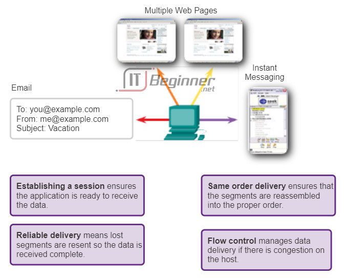
TCP was initially described in RFC 793. In addition to supporting the basic functions of data segmentation and reassembly, TCP, as shown in the figure, also provides:
- Connection-oriented conversations by establishing sessions
- Reliable delivery
- Ordered data reconstruction
- Flow control
Establishing a Session
TCP is a connection-oriented protocol. A connection-oriented protocol is one that negotiates and establishes a permanent connection (or session) between source and destination devices prior to forwarding any traffic. Session establishment prepares the devices to communicate with one another. Through session establishment, the devices negotiate the amount of traffic that can be forwarded at a given time, and the communication data between the two can be closely managed. The session is terminated only after all communication is completed.
Reliable Delivery
TCP can implement a method to ensure reliable delivery of the data. In networking terms, reliability means ensuring that each piece of data that the source sends arrives at the destination. For many reasons, it is possible for a piece of data to become corrupted, or lost completely, as it is transmitted over the network. TCP can ensure that all pieces reach their destination by having the source device retransmit lost or corrupted data.
Same-Order Delivery
Because networks may provide multiple routes that can have different transmission rates, data can arrive in the wrong order. By numbering and sequencing the segments, TCP can ensure that these segments are reassembled into the proper order.
Flow Control
Network hosts have limited resources, such as memory or bandwidth. When TCP is aware that these resources are overtaxed, it can request that the sending application reduce the rate of data flow. This is done by TCP regulating the amount of data the source transmits. Flow control can prevent the loss of segments on the network and avoid the need for retransmission.
7.1.2.2 Role of TCP
Once TCP establishes a session, it is then able to keep track of the conversation within that session. Because of the ability of TCP to track actual conversations, it is considered a stateful protocol. A stateful protocol is a protocol that keeps track of the state of the communication session. For example, when data is transmitted using TCP, the sender expects the destination to acknowledge that it has received the data. TCP tracks which information it has sent and which information has been acknowledged. If the data is not acknowledged, the sender assumes the data did not arrive and resends it. The stateful session begins with the session establishment and ends when the session is closed with session termination.
Note: Maintaining this state information requires resources that are not necessary for a stateless protocol, such as UDP.
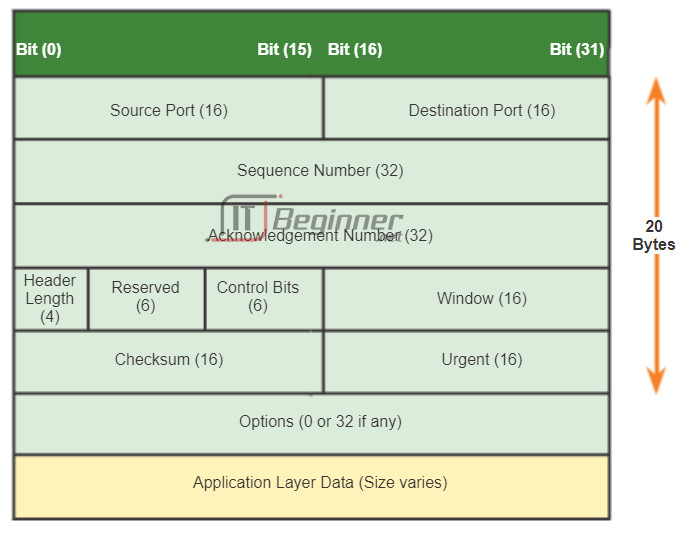
TCP incurs additional overhead to gain these functions. As shown in the figure, each TCP segment has 20 bytes of overhead in the header encapsulating the application layer data. This is considerably more than a UDP segment, which only has 8 bytes of overhead. Extra overhead includes:
- Sequence number (32 bits) – Used for data reassembly purposes.
- Acknowledgement number (32 bits) – Indicates the data that has been received.
- Header length (4 bits) – Known as ʺdata offsetʺ. Indicates the length of the TCP segment header.
- Reserved (6 bits) – This field is reserved for the future.
- Control bits (6 bits) – Includes bit codes, or flags, that indicate the purpose and function of the TCP segment.
- Window size (16 bits) – Indicates the number of segments that can be accepted at one time.
- Checksum (16 bits) – Used for error checking of the segment header and data.
- Urgent (16 bits) – Indicates if data is urgent.
Examples of applications that use TCP are web browsers, email, and file transfers.
7.1.2.3 Introducing UDP
User Datagram Protocol (UDP)
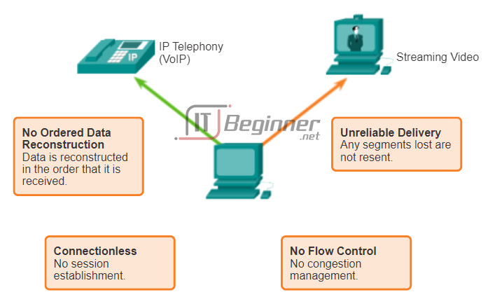
UDP is considered a best-effort transport protocol, described in RFC 768. UDP is a lightweight transport protocol that offers the same data segmentation and reassembly as TCP, but without TCP reliability and flow control. UDP is such a simple protocol, that it is usually described in terms of what it does not do compared to TCP.
As shown in the figure, the following features describe UDP:
- Connectionless – UDP does not establish a connection between the hosts before data can be sent and received.
- Unreliable Delivery – UDP does not provide services to ensure that the data will be delivered reliably. There are no processes within UDP to have the sender retransmit any data that is lost or is corrupted.
- No Ordered Data Reconstruction – Occasionally data is received in a different order than it was sent. UDP does not provide any mechanism for reassembling the data in its original sequence. The data is simply delivered to the application in the order that it arrives.
- No Flow Control – There are no mechanisms within UDP to control the amount of data transmitted by the source to avoid overwhelming the destination device. The source sends the data. If resources on the destination host become overtaxed, the destination host mostly likely drops data sent until resources become available. Unlike TCP, with UDP there is no mechanism for automatic retransmission of dropped data.
7.1.2.4 Role of UDP
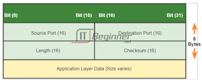
Although UDP does not include the reliability and flow control mechanisms of TCP, as shown in the figure, UDP’s low overhead data delivery makes it an ideal transport protocol for applications that can tolerate some data loss. The pieces of communication in UDP are called datagrams. These datagrams are sent as best effort by the transport layer protocol. A few applications that use UDP are Domain Name System (DNS), video streaming, and Voice over IP (VoIP).
One of the most important requirements for delivering live video and voice over the network is that the data continues to flow quickly. Video and voice applications can tolerate some data loss with minimal or no noticeable effect, and are perfectly suited to UDP.
UDP is a stateless protocol, meaning neither the client, nor the server, is obligated to keep track of the state of the communication session. As shown in the figure, UDP is not concerned with reliability or flow control. Data may be lost or received out of sequence without any UDP mechanisms to recover or reorder the data. If reliability is required when using UDP as the transport protocol, it must be handled by the application.
7.1.2.5 Separating Multiple Communications
The transport layer must be able to separate and manage multiple communications with different transport requirement needs. For example, consider a user connected to a network on an end device. The user is simultaneously receiving and sending email and instant messages, viewing websites, and conducting a Voice over IP (VoIP) phone call. Each of these applications is sending and receiving data over the network at the same time, despite different reliability requirements. Additionally, data from the phone call is not directed to the web browser, and text from an instant message does not appear in an email.
For reliability, users require that an email or web page be completely received and presented in full, for the information to be considered useful. Slight delays in loading the email or webpage are generally acceptable, as long as the final product is shown in its entirety and correctly. In this example, the network manages the resending or replacement of missing information, and does not display the final product until everything is received and correctly assembled.
In contrast, occasionally missing small parts of a telephone conversation might be considered acceptable. Even if some small parts of a few words are dropped, one can either infer the missing audio from the context of the conversation or ask the other person to repeat what was said. This is considered preferable to the incurred delays if the network were to manage and resend missing segments. In this example, the user, not the network, manages the resending or replacement of missing information.
As shown in the figure, for TCP and UDP to manage these simultaneous conversations with varying requirements, the TCP and UDP-based services must keep track of the various applications communicating. To differentiate the segments and datagrams for each application, both TCP and UDP have header fields that can uniquely identify these applications. These unique identifiers are the port numbers.
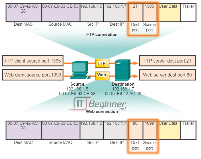
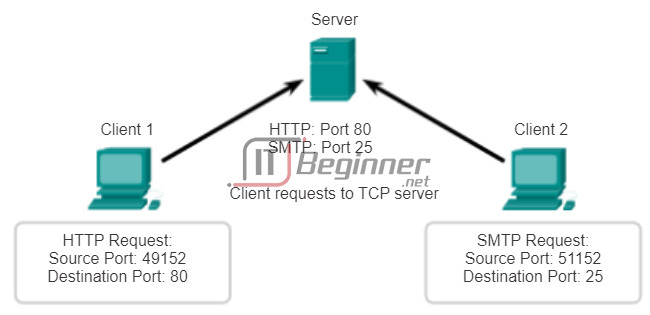
7.1.2.6 TCP and UDP Port Addressing
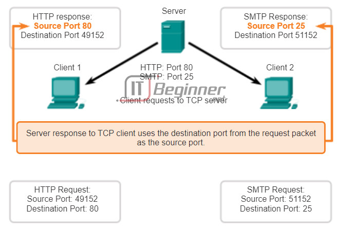
In the header of each segment or datagram, there is a source and destination port. The source port number is the number for this communication associated with the originating application on the local host. As shown in the figure, the destination port number is the number for this communication associated with the destination application on the remote host.
When a message is delivered using either TCP or UDP, the protocols and services requested are identified by a port number. A port is a numeric identifier within each segment that is used to keep track of specific conversations and destination services requested. Every message that a host sends contains both a source and destination port.
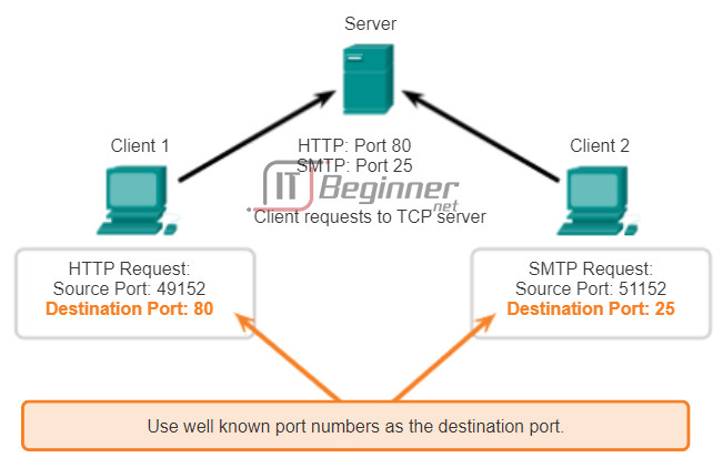
Destination Port
The client places a destination port number in the segment to tell the destination server what service is being requested. For example, port 80 refers to HTTP or web service. When a client specifies port 80 in the destination port, the server that receives the message knows that web services are being requested. A server can offer more than one service simultaneously. For example, a server can offer web services on port 80 at the same time that it offers FTP connection establishment on port 21.
Source Port
The source port number is randomly generated by the sending device to identify a conversation between two devices. This allows multiple conversations to occur simultaneously. In other words, a device can send multiple HTTP service requests to a web server at the same time. The separate conversations are tracked based on the source ports.
7.1.2.7 TCP and UDP Port Addressing (Cont.)
The source and destination ports are placed within the segment. The segments are then encapsulated within an IP packet. The IP packet contains the IP address of the source and destination. The combination of the source and destination IP addresses and the source and destination port numbers is known as a socket. The socket is used to identify the server and service being requested by the client. Every day thousands of hosts communicate with millions of different servers. Those communications are identified by the sockets.
It is the combination of the transport layer port number, and the network layer IP address of the host, that uniquely identifies a particular application process running on an individual host device. This combination is called a socket. A socket pair, consisting of the source and destination IP addresses and port numbers, is also unique and identifies the specific conversation between the two hosts.
A client socket might look like this, with 1099 representing the source port number: 192.168.1.5:1099
The socket on a web server might be: 192.168.1.7:80
Together, these two sockets combine to form a socket pair: 192.168.1.5:1099, 192.168.1.7:80
With the creation of sockets, communication endpoints are known so that data can move from an application on one host to an application on another. Sockets enable multiple processes running on a client to distinguish themselves from each other, and multiple connections to a server process to be distinguished from each other.
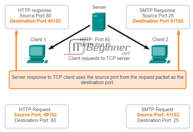
The source port of a client request is randomly generated. This port number acts like a return address for the requesting application. The transport layer keeps track of this port and the application that initiated the request so that when a response is returned, it can be forwarded to the correct application. The requesting application port number is used as the destination port number in the response coming back from the server.
7.1.2.8 TCP and UDP Port Addressing (Cont.)
The Internet Assigned Numbers Authority (IANA) assigns port numbers. IANA is a standards body that is responsible for assigning various addressing standards.
There are different types of port numbers, as shown in Figure 1:
- Well-known Ports (Numbers 0 to 1023) – These numbers are reserved for services and applications. They are commonly used for applications such as HTTP (web server), Internet Message Access Protocol (IMAP)/Simple Mail Transfer Protocol (SMTP) (email server) and Telnet. By defining these well-known ports for server applications, client applications can be programmed to request a connection to that specific port, and its associated service.
- Registered Ports (Numbers 1024 to 49151) – These port numbers are assigned to user processes or applications. These processes are primarily individual applications that a user has chosen to install, rather than common applications that would receive a well-known port number. When not used for a server resource, these ports may also be used dynamically selected by a client as its source port.
- Dynamic or Private Ports (Numbers 49152 to 65535) – Also known as ephemeral ports, these are usually assigned dynamically to client applications when the client initiates a connection to a service. The dynamic port is most often used to identify the client application during communication, whereas the client uses the well-known port to identify and connect to the service being requested on the server. It is uncommon for a client to connect to a service using a dynamic or private port (although some peer-to-peer file sharing programs do use these ports).
Figure 2 displays some common well-known and registered ports within TCP. Figure 3 displays common well-known and registered ports within UDP.
Using both TCP and UDP
Some applications may use both TCP and UDP (Figure 4). For example, the low overhead of UDP enables DNS to serve many client requests very quickly. Sometimes, however, sending the requested information may require the reliability of TCP. In this case, the well-known port number, 53, is used by both TCP and UDP with this service.
A current list of port numbers and the associated applications can be found on the IANA organizational website.
[tabs type=”horizontal”]
[tabs_head]
[tab_title]Figure 1[/tab_title]
[tab_title]Figure 2[/tab_title]
[tab_title]Figure 3[/tab_title]
[tab_title]Figure 4[/tab_title]
[/tabs_head]
[tab]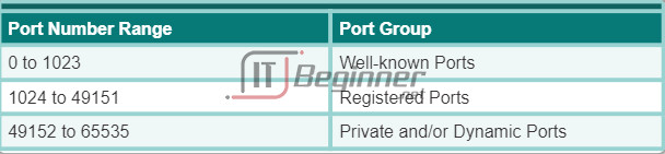 [/tab]
[tab]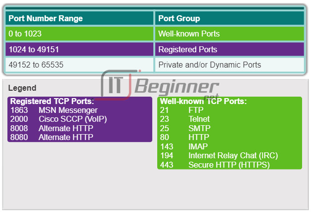 [/tab]
[tab]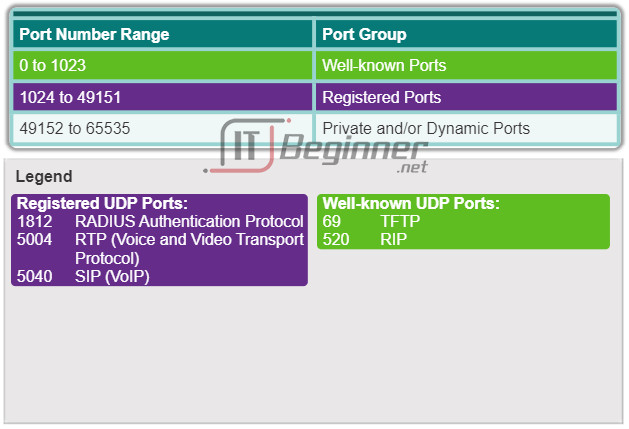 [/tab]
[tab]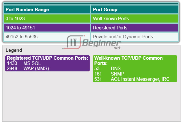 [/tab]
[/tabs]
7.1.2.9 TCP and UDP Port Addressing (Cont.)
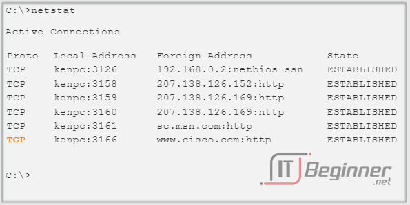
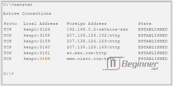
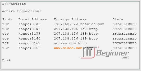
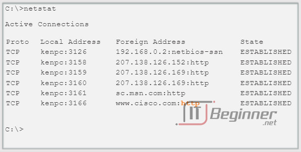
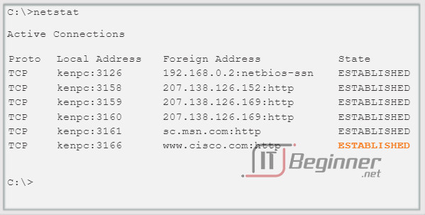
Sometimes it is necessary to know which active TCP connections are open and running on a networked host. Netstat is an important network utility that can be used to verify those connections. Netstat lists the protocol in use, the local address and port number, the foreign address and port number, and the connection state.
Unexplained TCP connections can pose a major security threat, because they can indicate that something or someone is connected to the local host. Additionally, unnecessary TCP connections can consume valuable system resources, thus slowing down the host’s performance. Netstat should be used to examine the open connections on a host when performance appears to be compromised.
Many useful options are available for the netstat command. Click the buttons in Figures 1 through 5 to see the different information output from the netstat command.
[tabs type=”horizontal”]
[tabs_head]
[tab_title]Figures 1[/tab_title]
[tab_title]Figures 2[/tab_title]
[tab_title]Figures 3[/tab_title]
[tab_title]Figures 4[/tab_title]
[tab_title]Figures 5[/tab_title]
[/tabs_head]
[tab]
[/tab]
[tab]
[/tab]
[tab]
[/tab]
[tab]
[/tab]
[tab]
[/tab]
[/tabs]
7.1.2.10 TCP and UDP Segmentation
A previous chapter explained how protocol data units (PDUs) are built by passing data from an application down through the various layers to create a PDU that is then transmitted on the medium. At the destination host, this process is reversed until the data can be passed up to the application.
Some applications transmit large amounts of data, in some cases, many gigabytes. It would be impractical to send all of this data in one large piece. No other network traffic could be transmitted while this data was being sent. A large piece of data could take minutes or even hours to send. In addition, if there were any errors, the entire data file would be lost or have to be resent. Network devices would not have memory buffers large enough to store this much data while it is transmitted or received. The limit varies depending on the networking technology and specific physical medium being in use.
Dividing application data into segments both ensures that data is transmitted within the limits of the media and that data from different applications can be multiplexed on to the media.
TCP and UDP Handle Segmentation Differently
As shown in the figure, each TCP segment header contains a sequence number that allows the transport layer functions on the destination host to reassemble segments in the order in which they were transmitted. This ensures that the destination application has the data in the exact form the sender intended.
Although services using UDP also track the conversations between applications; they are not concerned with the order in which the information was transmitted or concerned with maintaining a connection. There is no sequence number in the UDP header. UDP is a simpler design and generates less overhead than TCP, resulting in a faster transfer of data.
Information may arrive in a different order than it was transmitted, because different packets may take different paths through the network. An application that uses UDP must tolerate the fact that data may not arrive in the order in which it was sent.
7.1.2.11 Activity – Compare TCP and UDP Characteristics
7.2 TCP and UDP
7.2.1 TCP Communication
7.2.1.1 TCP Reliable Delivery
The key distinction between TCP and UDP is reliability. The reliability of TCP communication is obtained through the use of connection-oriented sessions. Before a host using TCP sends data to another host, TCP initiates a process to create a connection with the destination. This stateful connection enables the tracking of a session, or communication stream between the hosts. This process ensures that each host is aware of and prepared for the communication stream. A TCP conversation requires the establishment of a session between the hosts in both directions, as shown in the animation.
After a session has been established, and data transfer begins, the destination sends acknowledgements to the source for the segments that it receives. These acknowledgements form the basis of reliability within the TCP session. When the source receives an acknowledgement, it knows that the data has been successfully delivered and can quit tracking that data. If the source does not receive an acknowledgement within a predetermined amount of time, it retransmits that data to the destination.
Part of the additional overhead of using TCP is the network traffic generated by acknowledgements and retransmissions. The establishment of sessions creates overhead in the form of additional segments being exchanged. There is also additional overhead on the individual hosts created by the necessity to keep track of which segments are awaiting acknowledgement and by the retransmission process.
7.2.1.2 TCP Server Processes
Application processes run on servers. A single server may run multiple application processes at the same time. These processes wait until a client initiates communication with a request for information or other services.
Each application process running on the server is configured to use a port number, either by default or manually by a system administrator. An individual server cannot have two services assigned to the same port number within the same transport layer services. A host running a web server application and a file transfer application cannot have both configured to use the same port (for example, TCP port 8080). An active server application assigned to a specific port is considered to be open, which means that the transport layer accepts and processes segments addressed to that port. Any incoming client request addressed to the correct socket is accepted and the data is passed to the server application. There can be many simultaneous ports open on a server, one for each active server application. It is common for a server to provide more than one service at the same time, such as a web server and an FTP server.
One way to improve security on a server is to restrict server access to only those ports associated with the services and applications that should be accessible by authorized requestors.
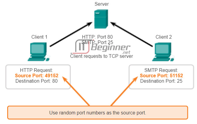
Refer to Figures 1 through 5 to see the typical allocation of source and destination ports in TCP client/server operations.
[tabs type=”horizontal”]
[tabs_head]
[tab_title]Figures 1[/tab_title]
[tab_title]Figures 2[/tab_title]
[tab_title]Figures 3[/tab_title]
[tab_title]Figures 4[/tab_title]
[tab_title]Figures 5[/tab_title]
[/tabs_head]
[tab]
[/tab]
[tab]
[/tab]
[tab]
[/tab]
[tab]
[/tab]
[tab]
[/tab]
[/tabs]
7.2.1.3 TCP Connection Establishment and Termination
In some cultures, when two persons meet, they often greet each other by shaking hands. The act of shaking hands is understood by both parties as a signal for a friendly greeting. Connections on the network are similar. The first handshake requests synchronization. The second handshake acknowledges the initial synchronization request and synchronizes the connection parameters in the opposite direction. The third handshake segment is an acknowledgment used to inform the destination that both sides agree that a connection has been established.
When two hosts communicate using TCP, a connection is established before data can be exchanged. After the communication is completed, the sessions are closed and the connection is terminated. The connection and session mechanisms enable TCP’s reliability function. See the figure for the steps to establish and terminate a TCP connection.
Hosts track each data segment within a session and exchange information about what data is received using the information in the TCP header. TCP is a full-duplex protocol, where each connection represents two one-way communication streams, or sessions. To establish the connection, the hosts perform a three-way handshake. Control bits in the TCP header indicate the progress and status of the connection. The three-way handshake:
- Establishes that the destination device is present on the network
- Verifies that the destination device has an active service and is accepting requests on the destination port number that the initiating client intends to use for the session
- Informs the destination device that the source client intends to establish a communication session on that port number
In TCP connections, the host client establishes the connection with the server. The three steps in TCP connection establishment are:
Step 1. The initiating client requests a client-to-server communication session with the server.
Step 2. The server acknowledges the client-to-server communication session and requests a server-to-client communication session.
Step 3. The initiating client acknowledges the server-to-client communication session.
In the figure, click through buttons 1 through 3 to see the TCP connection establishment.
To understand the three-way handshake process, look at the various values that the two hosts exchange. Within the TCP segment header, there are six 1-bit fields that contain control information used to manage the TCP processes. Those fields are:
- URG – Urgent pointer field significant
- ACK – Acknowledgement field significant
- PSH – Push function
- RST – Reset the connection
- SYN – Synchronize sequence numbers
- FIN – No more data from sender
The ACK and SYN fields are relevant to our analysis of the three-way handshake.
7.2.1.4 TCP Three-way Handshake Analysis – Step 1
Using the output of protocol analysis software, such as Wireshark outputs, you can examine the operation of the TCP 3-way handshake:
Step 1: The initiating client requests a client-to-server communication session with the server.
A TCP client begins the three-way handshake by sending a segment with the synchronize sequence number (SYN) control flag set, indicating an initial value in the sequence number field in the header. This initial value for the sequence number, known as the initial sequence number (ISN), is randomly chosen and is used to begin tracking the flow of data from the client to the server for this session. The ISN in the header of each segment is increased by one for each byte of data sent from the client to the server as the data conversation continues.
As shown in the figure, output from a protocol analyzer shows the SYN control flag and the relative sequence number.
The SYN control flag is set and the relative sequence number is at 0. Although the protocol analyzer in the graphic indicates the relative values for the sequence and acknowledgement numbers, the true values are 32-bit binary numbers. The figure shows the four bytes represented in hexadecimal.
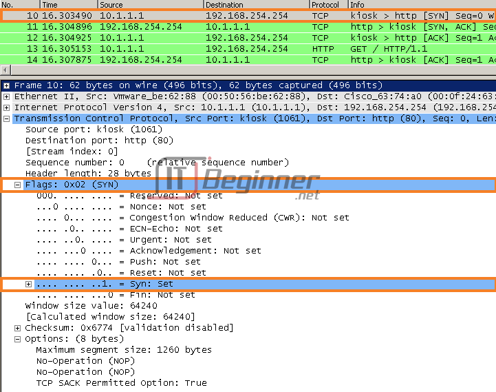
A protocol analyzer shows initial client request for session in frame 10TCP segment in this frame shows:
SYN flag set to validate an Initial Sequence Number
- Randomized sequence number valid (relative value is 0)
- Random source port 1061
- Well-known destination port is 80 (HTTP port) indicates web server (httpd)
7.2.1.5 TCP Three-way Handshake Analysis – Step 2
Step 2: The server acknowledges the client-to-server communication session and requests a server-to-client communication session.
The TCP server must acknowledge the receipt of the SYN segment from the client to establish the session from the client to the server. To do so, the server sends a segment back to the client with the acknowledgement (ACK) flag set indicating that the acknowledgment number is significant. With this flag set in the segment, the client recognizes this as an acknowledgement that the server received the SYN from the TCP client.
The value of the acknowledgment number field is equal to the ISN plus 1. This establishes a session from the client to the server. The ACK flag remains set for the balance of the session. Recall that the conversation between the client and the server is actually two one-way sessions: one from the client to the server, and the other from the server to the client. In this second step of the three-way handshake, the server must initiate the response to the client. To start this session, the server uses the SYN flag in the same way that the client did. It sets the SYN control flag in the header to establish a session from the server to the client. The SYN flag indicates that the initial value of the sequence number field is in the header. This value is used to track the flow of data in this session from the server back to the client.
As shown in the figure, the protocol analyzer output shows that the ACK and SYN control flags are set and the relative sequence and acknowledgement numbers are displayed.
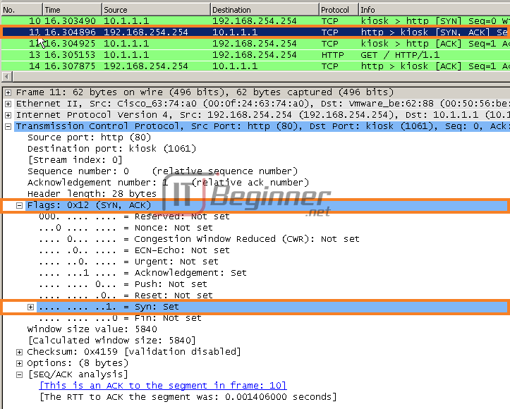
A protocol analyzer shows server response in frame 11
- ACK flag set to indicate a valid Acknowledgement number
- Acknowledgement number response to initial sequence number as relative value of 1
- SYN flag set to indicate the Initial Sequence Number for the server to client session
- Destination port number of 1061 to corresponding to the clients source port
- Source port number of 80 (HTTP) indicating the web server service (httpd)
7.2.1.6 TCP Three-way Handshake Analysis – Step 3
Step 3: The initiating client acknowledges the server-to-client communication session.
Finally, the TCP client responds with a segment containing an ACK that is the response to the TCP SYN sent by the server. There is no user data in this segment. The value in the acknowledgment number field contains one more than the ISN received from the server. After both sessions are established between client and server, all additional segments exchanged in this communication will have the ACK flag set.
As shown in the figure, the protocol analyzer output shows the ACK control flag set and the relative sequence and acknowledgement numbers.
Security can be added to the data network by:
- Denying the establishment of TCP sessions
- Only allowing sessions to be established for specific services
- Only allowing traffic as a part of already established sessions
These security measures can be implemented for all TCP sessions or only for selected sessions.
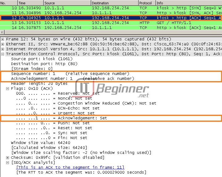
A protocol analyzer shows client response to session in frame 12
The TCP segment in this frame shows:
- ACK flag set to indicate a valid Acknowledgement number
- Acknowledgement number response to initial sequence number as relative value of 1
- Source port number of 1061 to corresponding
- Destination port number of 80 (HTTP) indicating the web server service (httpd)
7.2.1.7 TCP Session Termination Analysis
To close a connection, the Finish (FIN) control flag must be set in the segment header. To end each one-way TCP session, a two-way handshake is used, consisting of a FIN segment and an ACK segment. Therefore, to terminate a single conversation supported by TCP, four exchanges are needed to end both sessions, as shown in Figure 1.
Note: In this explanation, the terms client and server are used as a reference for simplicity, but the termination process can be initiated by any two hosts that have an open session:
Step 1: When the client has no more data to send in the stream, it sends a segment with the FIN flag set.
Step 2: The server sends an ACK to acknowledge the receipt of the FIN to terminate the session from client to server.
Step 3: The server sends a FIN to the client, to terminate the server to client session.
Step 4: The client responds with an ACK to acknowledge the FIN from the server.
When the client has no more data to transfer, it sets the FIN flag in the header of a segment. Next, the server end of the connection sends a normal segment containing data with the ACK flag set using the acknowledgment number, confirming that all the bytes of data have been received. When all segments have been acknowledged, the session is closed.
The session in the other direction is closed using the same process. The receiver indicates that there is no more data to send by setting the FIN flag in the header of a segment sent to the source. A return acknowledgement confirms that all bytes of data have been received and that session is, in turn, closed.
Refer to Figures 2 and 3 to see the FIN and ACK control flags set in the segment header, thereby closing a HTTP session.
It is also possible to terminate the connection by a three-way handshake. When the client has no more data to send, it sends a FIN to the server. If the server also has no more data to send, it can reply with both the FIN and ACK flags set, combining two steps into one. The client then replies with an ACK.
[tabs type=”horizontal”]
[tabs_head]
[tab_title]Figures 1[/tab_title]
[tab_title]Figures 2[/tab_title]
[tab_title]Figures 3[/tab_title]
[/tabs_head]
[tab]
[/tab]
[tab]
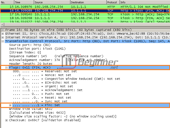
- A protocol analyzer shows details of frame 16, TCP FIN request.
[/tab]
[tab]
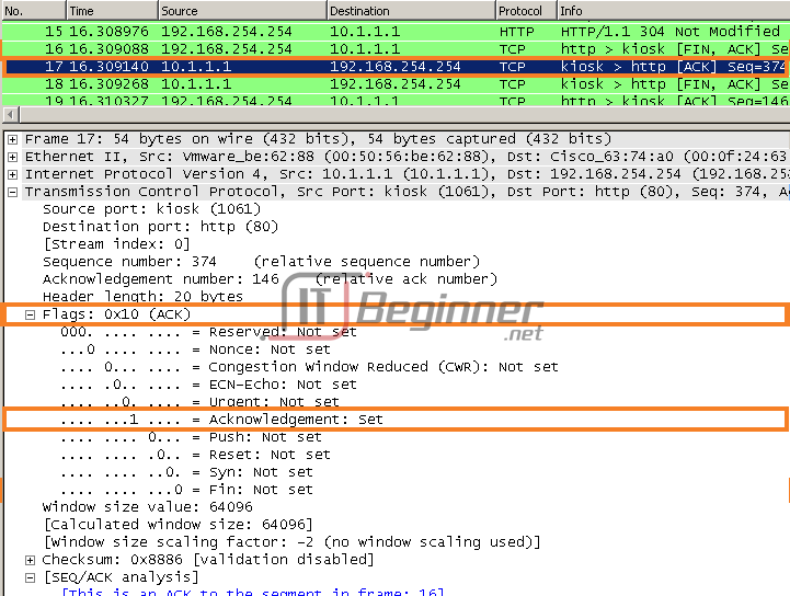
- A protocol analyzer shows details of frame 17, TCP ACK response.
[/tab]
[/tabs]
7.2.1.8 Lab – Using Wireshark to Observe the TCP 3-Way Handshake
In this lab, you will complete the following objectives:
- Part 1: Prepare Wireshark to Capture Packets
- Part 2: Capture, Locate, and Examine Packets
Lab – Using Wireshark to Observe the TCP 3-Way Handshake ./.
7.2.1.9 Activity – TCP Connection and Termination Process
7.2.2 Reliability and Flow Control
7.2.2.1 TCP Reliability – Ordered Delivery
Resequencing Segments
When services send data using TCP, segments may arrive at their destination out of order. For the original message to be understood by the recipient, the data in these segments is reassembled into the original order. Sequence numbers are assigned in the header of each packet to achieve this goal.
During session setup, an initial sequence number (ISN) is set. This ISN represents the starting value for the bytes for this session that is transmitted to the receiving application. As data is transmitted during the session, the sequence number is incremented by the number of bytes that have been transmitted. This data byte tracking enables each segment to be uniquely identified and acknowledged. Missing segments can be identified.
Segment sequence numbers enable the reliability by indicating how to reassemble and reorder received segments, as shown in the figure.
The receiving TCP process places the data from a segment into a receiving buffer. Segments are placed in the proper sequence number order and passed to the application layer when reassembled. Any segments that arrive with non-contiguous sequence numbers are held for later processing. Then, when the segments with the missing bytes arrive, these segments are processed in order.
7.2.2.2 TCP Reliability – Acknowledgement and Window Size
Confirming Receipt of Segments
One of the functions of TCP is ensuring that each segment reaches its destination. The TCP services on the destination host acknowledge the data that it has received by the source application.
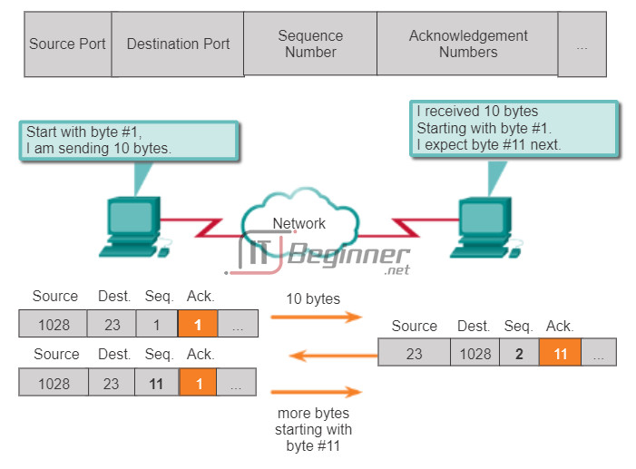
The sequence (SEQ) number and acknowledgement (ACK) number are used together to confirm receipt of the bytes of data contained in the transmitted segments. The SEQ number indicates the relative number of bytes that have been transmitted in this session, including the bytes in the current segment. TCP uses the ACK number sent back to the source to indicate the next byte that the receiver expects to receive. This is called expectational acknowledgement.
The source is informed that the destination has received all bytes in this data stream up to, but not including, the byte indicated by the ACK number. The sending host is expected to send a segment that uses a sequence number that is equal to the ACK number.
Remember, each connection is actually two one-way sessions. SEQ and ACK numbers are being exchanged in both directions.
In the example in the figure, the host on the left is sending data to the host on the right. It sends a segment containing 10 bytes of data for this session and a sequence number equal to 1 in the header.
The receiving host receives the segment at Layer 4 and determines that the sequence number is 1 and that it has 10 bytes of data. The host then sends a segment back to the host on the left to acknowledge the receipt of this data. In this segment, the host sets the ACK number to 11 to indicate that the next byte of data it expects to receive in this session is byte number 11. When the sending host receives this acknowledgement, it can now send the next segment containing data for this session starting with byte number 11.
Looking at this example, if the sending host had to wait for acknowledgement of receiving each 10 bytes, the network would have a lot of overhead. To reduce the overhead of these acknowledgements, multiple segments of data can be sent and acknowledged with a single TCP message in the opposite direction. This acknowledgement contains an ACK number based on the total number of bytes received in the session. For example, starting with a sequence number of 2000, if 10 segments of 1,000 bytes each were received, an ACK number of 12001 would be returned to the source.
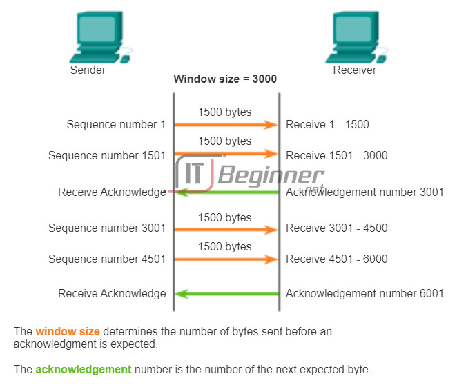
The amount of data that a source can transmit before an acknowledgement must be received is called the window size, which is a field in the TCP header that enables the management of lost data and flow control.
7.2.2.3 TCP Reliability – Data Loss and Retransmission
Handling Segment Loss
No matter how well designed a network is, data loss occasionally occurs; therefore, TCP provides methods of managing these segment losses. Among these is a mechanism to retransmit segments with unacknowledged data.
A destination host service using TCP usually only acknowledges data for contiguous sequence bytes. If one or more segments are missing, only the data in the first contiguous sequence of bytes is acknowledged. For example, if segments with sequence numbers 1500 to 3000 and 3400 to 3500 were received, the ACK number would be 3001. This is because there are segments with the SEQ numbers 3001 to 3399 that have not been received.
When TCP at the source host has not received an acknowledgement after a predetermined amount of time, it returns to the last ACK number received and retransmits the data from that point forward. The retransmission process is not specified by the Request for Comments (RFC), but is left up to the particular implementation of TCP.
For a typical TCP implementation, a host may transmit a segment, put a copy of the segment in a retransmission queue, and start a timer. When the data acknowledgment is received, the segment is deleted from the queue. If the acknowledgment is not received before the timer expires, the segment is retransmitted.
Click the Play button in the figure to see the animation demonstrate the retransmission of lost segments.
Hosts today may also employ an optional feature called selective acknowledgements (SACKs). If both hosts support SACKs, it is possible for the destination to acknowledge bytes in discontinuous segments and the host would only need to retransmit the missing data.
7.2.2.4 TCP Flow Control – Window Size and Acknowledgements
Flow Control
TCP also provides mechanisms for flow control. Flow control helps maintain the reliability of TCP transmission by adjusting the rate of data flow between source and destination for a given session. Flow control is accomplished by limiting the amount of data segments forwarded at one time and by requiring acknowledgments of receipt prior to sending more.
To accomplish flow control, the first thing that TCP determines is the amount of data segments that the destination device can accept. The TCP header includes a 16-bit field called the window size. This is the number of bytes that the destination device of a TCP session is able to accept and process at one time. The initial window size is agreed upon during the session startup via the three-way handshake between source and destination. Once agreed upon, the source device must limit the amount of data segments sent to the destination device based on the window size. Only after the source device receives an acknowledgement that the data segments have been received, can it continue sending more data for the session.
During the delay in receiving the acknowledgement, the sender does not send any additional segments. In periods when the network is congested or the resources of the receiving host are strained, the delay may increase. As this delay grows longer, the effective transmission rate of the data for this session decreases. The slowdown in data transmission from each session helps reduce resource conflict on the network and destination device when multiple sessions are running.
See the figure for a simplified representation of window size and acknowledgements. In this example, the initial window size for a TCP session represented is set to 3000 bytes. When the sender has transmitted 3000 bytes, it waits for an acknowledgement of these bytes before transmitting more segments in this session. After the sender has received an acknowledgement from the receiver, the sender can transmit an additional 3000 bytes.
TCP uses window sizes to attempt to manage the rate of transmission to the maximum flow that the network and destination device can support, while minimizing loss and retransmissions.
7.2.2.5 TCP Flow Control – Congestion Avoidance
Reducing Window Size
Another way to control the data flow is to use dynamic window sizes. When network resources are constrained, TCP can reduce the window size to require that received segments be acknowledged more frequently. This effectively slows down the rate of transmission because the source waits for data to be acknowledged more frequently.
The receiving host sends the window size value to the sending host to indicate the number of bytes that it is prepared to receive. If the destination needs to slow down the rate of communication because of limited buffer memory, for example, it can send a smaller window size value to the source as part of an acknowledgement.
As shown in the figure, if a receiving host has congestion, it may respond to the sending host with a segment that specifies a reduced window size. In this figure, there was a loss of one of the segments. The receiver changed the window field in the TCP header of the returning segments in this conversation from 3,000 down to 1,500, which caused the sender to reduce the window size to 1,500.
After a period of transmission with no data losses or constrained resources, the receiver begins to increase the window field, which reduces the overhead on the network, because fewer acknowledgments must be sent. The window size continues to increase until there is data loss, which causes the window size to decrease.
This dynamic increasing and decreasing of window size is a continuous process in TCP. In highly efficient networks, window sizes may become very large because data is not lost. In networks where the underlying infrastructure is under stress, the window size likely remains small.
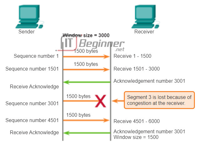
- If segments are lost because of congestion, the receiver will acknowledge the last received sequential segment and reply with a reduced window size.
7.2.3 UDP Communication
7.2.3.1 UDP Low Overhead versus Reliability
UDP is a simple protocol that provides the basic transport layer functions. It has much lower overhead than TCP, because it is not connection-oriented and does not offer the sophisticated retransmission, sequencing, and flow control mechanisms that provide reliability.
This does not mean that applications that use UDP are always unreliable, nor does it mean that UDP is an inferior protocol. It simply means that these functions are not provided by the transport layer protocol and must be implemented elsewhere, if required.
Although the total amount of UDP traffic found on a typical network is often relatively low, key application layer protocols that use UDP include:
- Domain Name System (DNS)
- Simple Network Management Protocol (SNMP)
- Dynamic Host Configuration Protocol (DHCP)
- Routing Information Protocol (RIP)
- Trivial File Transfer Protocol (TFTP)
- IP telephony or Voice over IP (VoIP)
- Online games
Some applications, such as online games or VoIP, can tolerate some data loss. If these applications used TCP, they could experience large delays while TCP detects data loss and retransmits data. These delays would be more detrimental to the performance of the application than small data losses. Some applications, such as DNS, simply retry the request if no response is received; therefore, they do not need TCP to guarantee message delivery.
The low overhead of UDP makes it very desirable for such applications.
UDP provides low overhead data transport because it has a small datagram header and no network management traffic.
7.2.3.2 UDP Datagram Reassembly
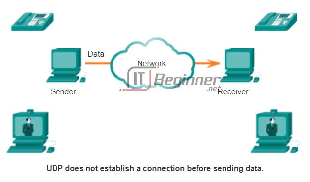
Because UDP is connectionless, sessions are not established before communication takes place as they are with TCP. UDP is said to be transaction-based; that is, when an application has data to send, it simply sends the data.
Many applications that use UDP send small amounts of data that can fit in one segment. However, some applications send larger amounts of data that must be split into multiple segments. The UDP PDU is referred to as a datagram, although the terms segment and datagram are sometimes used interchangeably to describe a transport layer PDU.
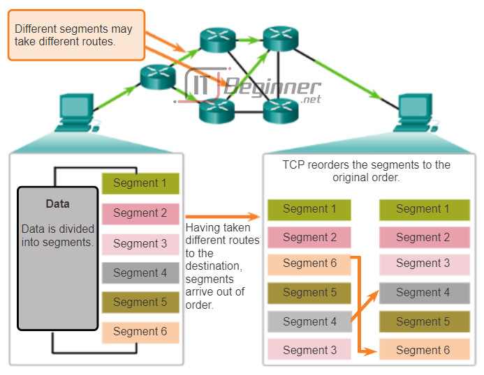
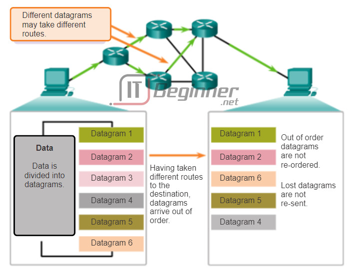
When multiple datagrams are sent to a destination, they may take different paths and arrive in the wrong order. UDP does not track sequence numbers the way TCP does. UDP has no way to reorder the datagrams into their transmission order, as shown in the figure.
Therefore, UDP simply reassembles the data in the order that it was received and forwards it to the application. If the data sequence is important to the application, the application must identify the proper sequence and determine how the data should be processed.
7.2.3.3 UDP Server Processes and Requests
Like TCP-based applications, UDP-based server applications are assigned well-known or registered port numbers. When these applications or processes are running on a server, they accept the data matched with the assigned port number. When UDP receives a datagram destined for one of these ports, it forwards the application data to the appropriate application based on its port number.
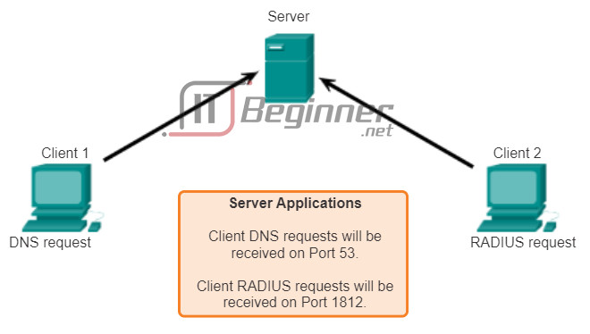
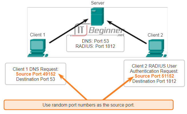
7.2.3.4 UDP Client Processes
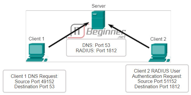
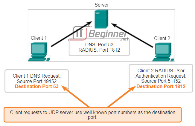
As with TCP, client/server communication is initiated by a client application that requests data from a server process. The UDP client process randomly selects a port number from the range of dynamic port numbers and uses this as the source port for the conversation. The destination port is usually the well-known or registered port number assigned to the server process.
Randomized source port numbers also help with security. If there is a predictable pattern for destination port selection, an intruder can more easily simulate access to a client by attempting to connect to the port number most likely to be open.
Because there is no session to be created with UDP, as soon as the data is ready to be sent and the ports identified, UDP can form the datagrams and pass them to the network layer to be addressed and sent on the network.
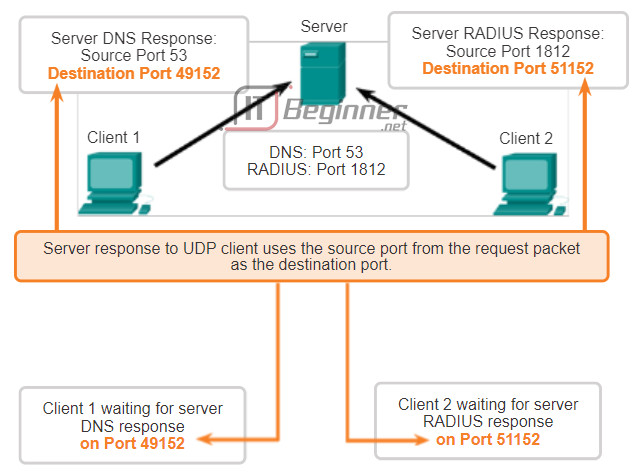
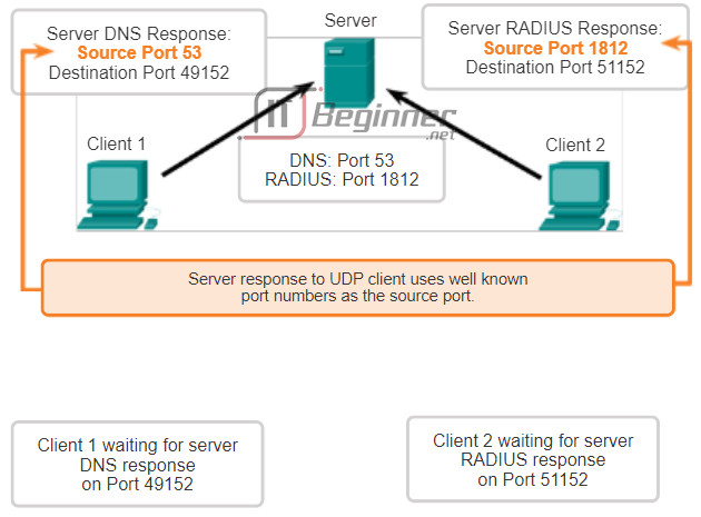
After a client has selected the source and destination ports, the same pair of ports is used in the header of all datagrams used in the transaction. For the data returning to the client from the server, the source and destination port numbers in the datagram header are reversed.
Scroll through the figures on the right to see details of UDP client processes.
[tabs type=”horizontal”]
[tabs_head]
[tab_title]Figures 1[/tab_title]
[tab_title]Figures 2[/tab_title]
[tab_title]Figures 3[/tab_title]
[tab_title]Figures 4[/tab_title]
[tab_title]Figures 5[/tab_title]
[/tabs_head]
[tab]
[/tab]
[tab]
[/tab]
[tab]
[/tab]
[tab]
[/tab]
[tab]
[/tab]
[/tabs]
7.2.3.5 Lab – Using Wireshark to Examine a UDP DNS Capture
In this lab, you will complete the following objectives:
- Part 1: Record a PC’s IP Configuration Information
- Part 2: Use Wireshark to Capture DNS Queries and Responses
- Part 3: Analyze Captured DNS or UDP Packets
Lab – Using Wireshark to Examine a UDP DNS Capture ./.
7.2.4 TCP or UDP, that is the Question
7.2.4.1 Applications that use TCP
Many applications require reliability and other services provided by TCP. These are applications that can tolerate some delay or performance loss due to the overhead imposed by TCP.
This makes TCP best suited for applications that need reliable transport and can tolerate some delay. TCP is a great example of how the different layers of the TCP/IP protocol suite have specific roles. Because the transport layer protocol TCP handles all tasks associated with segmenting the data stream into segments, reliability, flow control, and reordering of segments, it frees the application from having to manage any of this. The application can simply send the data stream to the transport layer and use the services of TCP.
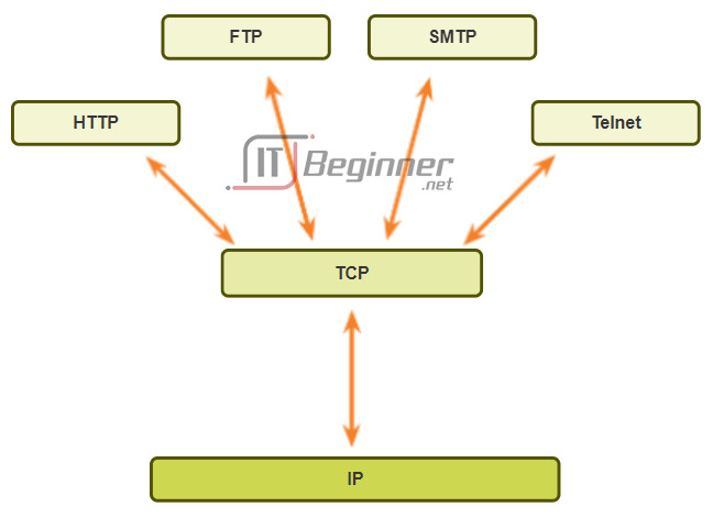
As shown in the figure, some examples of well-known applications that use TCP include:
- Hypertext Transfer Protocol (HTTP)
- File Transfer Protocol (FTP)
- Simple Mail Transfer Protocol (SMTP)
- Telnet
7.2.4.2 Applications that use UDP
There are three types of applications that are best suited for UDP:
- Applications that can tolerate some data loss, but require little or no delay
- Applications with simple request and reply transactions
- Unidirectional communications where reliability is not required or can be handled by the application
Many video and multimedia applications, such as VoIP and Internet Protocol Television (IPTV) use UDP. These applications can tolerate some data loss with little or no noticeable effect. The reliability mechanisms of TCP introduce some delay that can be noticeable in the quality of the sound or video being received.
Other types of applications well suited for UDP are those that use simple request and reply transactions. This is where a host sends a request and may or may not receive a reply. These types of applications include:
- DHCP
- DNS – May also use TCP
- SNMP
- TFTP
Some applications handle reliability themselves. These applications do not need the services of TCP, and can better utilize UDP as the transport layer protocol. TFTP is one example of this type of protocol. TFTP has its own mechanisms for flow control, error detection, acknowledgements, and error recovery. It does not need to rely on TCP for those services.
7.2.4.3 Lab – Using Wireshark to Examine FTP and TFTP Captures
In this lab, you will complete the following objectives:
- Part 1: Identify TCP Header Fields and Operation Using a Wireshark FTP Session Capture
- Part 2: Identify UDP Header Fields and Operation Using a Wireshark TFTP Session Capture
Lab – Using Wireshark to Examine FTP and TFTP Captures ./.
7.3 Summary
7.3.1 Summary
7.3.1.1 Class Activity – We Need to Talk, Again – Game
Note: It is important that the students have completed the Introductory Modeling Activity for this chapter. This activity works best in medium-sized groups of 6 to 8 students.
The instructor will whisper a complex message to the first student in a group. An example of the message might be “We are expecting a blizzard tomorrow. It should be arriving in the morning and school will be delayed two hours so bring your homework.”
That student whispers the message to the next student in the group. Each group follows this process until all members of each group have heard the whispered message.
Here are the rules you are to follow:
- You can whisper the message in short parts to your neighbor AND you can repeat the message parts after verifying your neighbor heard the correct message.
- Small parts of the message may be checked and repeated again (clockwise OR counter-clockwise to ensure accuracy of the message parts) by whispering. A student will be assigned to time the entire activity.
- When the message has reached the end of the group, the last student will say aloud what she or he heard. Small parts of the message may be repeated (i.e., re-sent), and the process can be restarted to ensure that ALL parts of the message are fully delivered and correct.
- The Instructor will restate the original message to check for quality delivery.
Class Activity – We Need to Talk, Again Instructions ./.

TCP and UDP are transport layer protocols instrumental in ensuring that…
- Network communications with different levels of importance are sent/received according to their levels of importance.
- The type of data will affect whether TCP or UDP will be used as the method of delivery.
- Timing is a factor and will affect how long it takes to send/receive TCP/UDP data transmissions.
7.3.1.2 Packet Tracer Simulation – TCP and UDP Communications
This simulation activity is intended to provide a foundation for understanding the TCP and UDP in detail. Simulation mode provides the ability to view the functionality of the different protocols.
As data moves through the network, it is broken down into smaller pieces and identified in some fashion so that the pieces can be put back together. Each of these pieces is assigned a specific name (protocol data unit [PDU]) and associated with a specific layer. Packet Tracer Simulation mode enables the user to view each of the protocols and the associated PDU. The steps outlined below lead the user through the process of requesting services using various applications available on a client PC.
This activity provides an opportunity to explore the functionality of the TCP and UDP protocols, multiplexing and the function of port numbers in determining which local application requested the data or is sending the data.
Packet Tracer Simulation – TCP and UDP Communications Instructions ./.
Packet Tracer Simulation – TCP and UDP Communications – PKA ./.
7.3.1.3 Summary
The transport layer provides transport-related services by:
- Dividing data received from an application into segments
- Adding a header to identify and manage each segment
- Using the header information to reassemble the segments back into application data
- Passing the assembled data to the correct application
UDP and TCP are common transport layer protocols.
UDP datagrams and TCP segments have headers added in front of the data that include a source port number and destination port number. These port numbers enable data to be directed to the correct application running on the destination computer.
TCP does not pass any data to the network until it knows that the destination is ready to receive it. TCP then manages the flow of the data and resends any data segments that are not acknowledged as being received at the destination. TCP uses mechanisms of handshaking, timers, acknowledgement messages, and dynamic windowing to achieve reliability. The reliability process, however, imposes overhead on the network in terms of much larger segment headers and more network traffic between the source and destination.
If the application data needs to be delivered across the network quickly, or if network bandwidth cannot support the overhead of control messages being exchanged between the source and the destination systems, UDP would be the developer’s preferred transport layer protocol. Because UDP does not track or acknowledge the receipt of datagrams at the destination – it just passes received datagrams to the application layer as they arrive – and does not resend lost datagrams. However, this does not necessarily mean that the communication itself is unreliable; there may be mechanisms in the application layer protocols and services that process lost or delayed datagrams if the application has these requirements.
The application developer decides the transport layer protocol that best meets the requirements for the application. It is important to remember that the other layers all play a part in data network communications and influences its performance.