Introduction to Networks Instructor Materials – Chapter 10: Application Layer
10.0 Application Layer
10.0.1 Introduction
10.0.1.1 Introduction
We experience the Internet through the World Wide Web when streaming videos, playing online games, chatting with and emailing friends, and shopping for deals on web sites. Applications, such as the ones used to provide the services mentioned, provide the human interface to the underlying network. They enable us to send and receive data with relative ease. Typically we can access and use these applications without knowing how they work. However, for network professionals, it is important to know how an application is able to format, transmit and interpret messages that are sent and received across the network.
Visualizing the mechanisms that enable communication across the network is made easier if we use the layered framework of the OSI model.
In this chapter, we will explore the role of the application layer and how the applications, services, and protocols within the application layer make robust communication across data networks possible.
Upon completion of this chapter you will be able to:
- Explain how the functions of the application layer, session layer, and presentation layer work together to provide network services to end user applications.
- Describe how common application layer protocols interact with end user applications.
- Describe, at a high level, common application layer protocols that provide Internet services to end-users, including WWW services and email.
- Describe application layer protocols that provide IP addressing services, including: DNS and DHCP.
- Describe the features and operation of well-known application layer protocols that allow for file sharing services, including: FTP, File Sharing Services, SMB protocol.
- Explain how data is moved across the network, from opening an application, to receiving data.
10.0.1.2 Activity – Application Investigation
What would happen if…
Your employer has decided to have IP telephones installed in your workplace resulting in the network being inoperable until next week.
Your work however, must continue. You have emails to send and quotes to write for your manager’s approval. Because of possible security issues, you are not allowed to use personal or external computer systems, equipment, or off-site equipment and systems, to complete your corporate workload.
Your instructor may ask you to complete the questions from both scenarios below, or to choose one scenario (A. Emails, or B. Quote for Manager’s Approval). Answer the questions fully for the scenario(s). Be prepared to discuss your answers in class.
A. Emails
- What method(s) can you use to send email communication?
- How could you send the same email to multiple recipients?
- How would you get a large attachment to multiple recipients, if necessary?
- Are these methods cost effective to your corporation?
- Do they violate any security policies of your corporation?
B. Quote for Manager’s Approval
- You have a desktop application software package installed on your computer. Will it be relatively easy to produce the quote your manager needs for the new contract due by the end of the week? What limitations will be experienced while trying to complete the quote?
- How will you present the quote to your manager for approval? How do you think he or she will send the quote to the client for their approval?
- Are these methods cost effective to your corporation? Justify your answer.
Class Activity – What would happen if… Instructions ./.

Network applications…
- make communication in the workplace easier
- affect the amount of work completed on a daily basis
- reduce data communications time and costs
10.1 Application Layer Protocols
10.1.1 Application, Session and Presentation
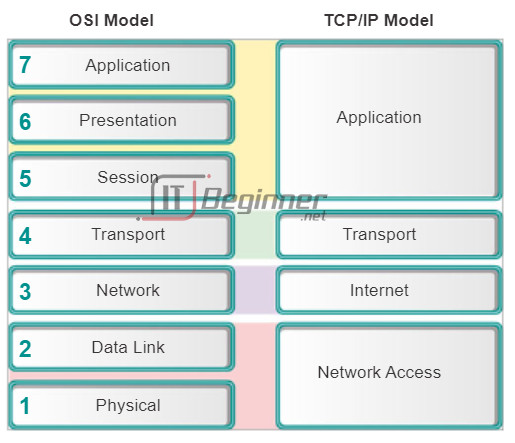
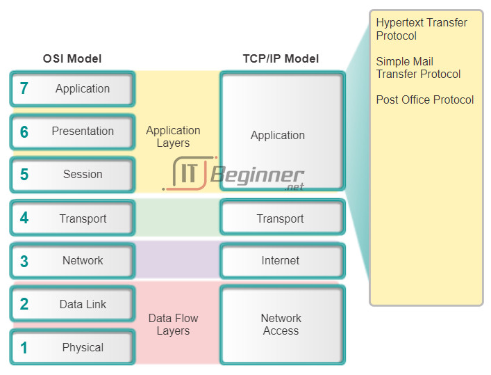
10.1.1.1 OSI and TCP/IP Models Revisited
As shown in the figure, networking professionals use the OSI and TCP/IP models to communicate both verbally and in written technical documentation. As such, networking professional can use these models to describe the behavior of protocols and applications.
In the OSI model, data is passed from one layer to the next, starting at the application layer on the transmitting host, and proceeding down the hierarchy to the physical layer, and then passing over the communications channel to the destination host, where the data proceeds back up the hierarchy, ending at the application layer.
The application layer is the top layer of both the OSI and TCP/IP models. The TCP/IP application layer includes a number of protocols that provide specific functionality to a variety of end-user applications. The functionality of the TCP/IP application layer protocols fit roughly into the framework of the top three layers of the OSI model: application, presentation and session layers. The OSI model Layers 5, 6, and 7 are used as references for application software developers and vendors to produce products, such as web browsers that need to access networks.
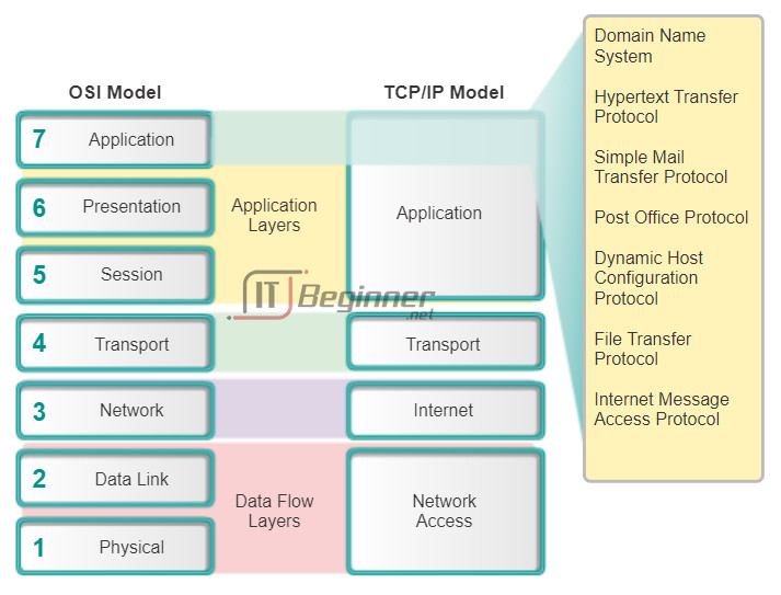
10.1.1.2 Application Layer
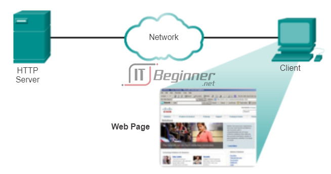
The application layer is closest to the end user. As shown in the figure, it is the layer that provides the interface between the applications we use to communicate and the underlying network over which our messages are transmitted. Application layer protocols are used to exchange data between programs running on the source and destination hosts. There are many application layer protocols and new protocols are always being developed. Some of the most widely known application layer protocols include Hypertext Transfer Protocol (HTTP), File Transfer Protocol (FTP), Trivial File Transfer Protocol (TFTP), Internet Message Access Protocol (IMAP), and Domain Name System (DNS) protocol.
10.1.1.3 Presentation and Session Layers
The Presentation Layer
The presentation layer has three primary functions:
- Formats, or presents, data from the source device into a compatible form for receipt by the destination device.
- Compression of the data in a way that can be decompressed by the destination device.
- Encryption of the data for transmission and the decryption of data upon receipt by the destination.
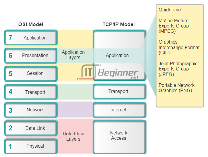
As shown in the figure, the presentation layer formats data for the application layer and it sets standards for file formats. Some well-known standards for video include QuickTime and Motion Picture Experts Group (MPEG). QuickTime is an Apple computer specification for video and audio, and MPEG is a standard for video and audio compression and coding.
Among the well-known graphic image formats that are used on networks are Graphics Interchange Format (GIF), Joint Photographic Experts Group (JPEG), and Portable Network Graphics (PNG) format. GIF and JPEG are compression and coding standards for graphic images. PNG was designed to address some of the limitations of the GIF format and to eventually replace it.
The Session Layer
As the name implies, functions at the session layer create and maintain dialogs between source and destination applications. The session layer handles the exchange of information to initiate dialogs, keep them active, and to restart sessions that are disrupted or idle for a long period of time.
10.1.1.4 TCP/IP Application Layer Protocols
While the OSI model separates the individual application, presentation, and session function, most widely known and implemented TCP/IP applications incorporate the functionality of all three layers.
The TCP/IP application protocols specify the format and control information necessary for many common Internet communication functions. Among these TCP/IP protocols are:
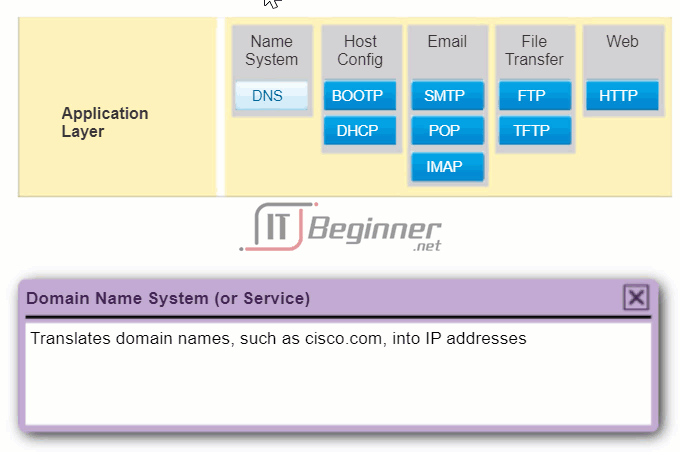
- Domain Name System (DNS) – This protocol resolves Internet names to IP addresses.
- Telnet – This is used to provide remote access to servers and networking devices.
- Simple Mail Transfer Protocol (SMTP) – This protocol transfers mail messages and attachments.
- Dynamic Host Configuration Protocol (DHCP) – A protocol used to assign an IP address, subnet mask, default gateway, and DNS server addresses to a host.
- Hypertext Transfer Protocol (HTTP) – This protocol transfers files that make up the web pages of the World Wide Web.
- File Transfer Protocol (FTP) – A protocol used for interactive file transfer between systems.
- Trivial File Transfer Protocol (TFTP) – This protocol is used for connectionless active file transfer.
- Bootstrap Protocol (BOOTP) – This protocol is a precursor to the DHCP protocol. BOOTP is a network protocol used to obtain IP address information during bootup.
- Post Office Protocol (POP) – A protocol used by email clients to retrieve email from a remote server.
- Internet Message Access Protocol (IMAP) – This is another protocol for email retrieval.
Application layer protocols are used by both the source and destination devices during a communication session. For the communications to be successful the application layer protocols implemented on the source and destination host must be compatible.
10.1.1.5 Activity – Application Protocols and Standards
10.1.2 How Application Protocols Interact with End-User Applications
10.1.2.1 Peer-to-Peer Networks
When accessing information on a networking device, whether it is a PC, laptop, tablet, smartphone, or some other device connected to a network, the data may not be physically stored on the device. In this case, a request to access that information must be made to the device where the data resides. In the peer-to-peer (P2P) networking model, the data is accessed from a peer device without the use of a dedicated server.
The P2P network model involves two parts: P2P networks and P2P applications. Both parts have similar features, but in practice work quite differently.
P2P Networks
In a P2P network, two or more computers are connected via a network and can share resources (such as printers and files) without having a dedicated server. Every connected end device (known as a peer) can function as both a server and a client. One computer might assume the role of server for one transaction while simultaneously serving as a client for another. The roles of client and server are set on a per request basis.
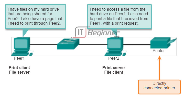
An example is a simple home network with two computers, as shown in the figure. In this example, Peer2 has a printer attached to it directly by USB, and is setup to share the printer on the network so that Peer1 can print to it. Peer1 is set up to share a drive or folder on the network. This allows Peer2 to access and save files to the shared folder. In addition to sharing files, a network such as this one would allow users to enable networked games, or share an Internet connection.
P2P networks decentralize the resources on a network. Instead of locating data to be shared on dedicated servers, data can be located anywhere and on any connected device. Most of the current operating systems support file and print sharing without requiring additional server software. However, P2P networks do not use centralized user accounts or access servers to maintain permissions. Therefore, it is difficult to enforce security and access policies in networks containing more than just a few computers. User accounts and access rights must be set individually on each peer device.
10.1.2.2 Peer-to-Peer Applications
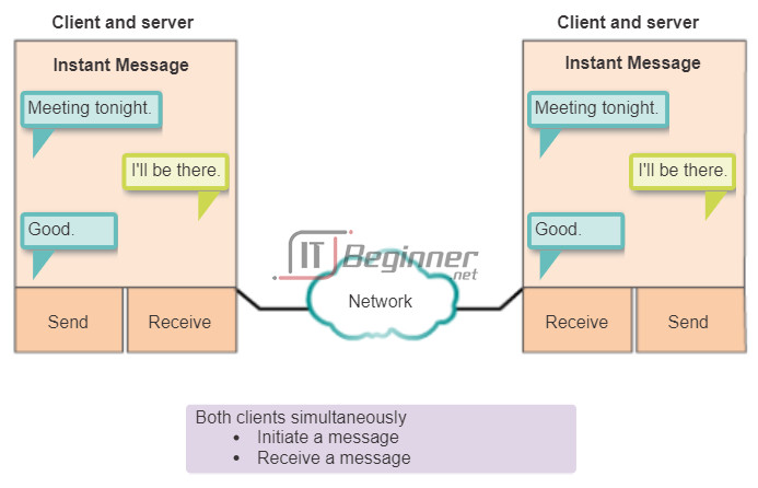
A peer-to-peer (P2P) application allows a device to act as both a client and a server within the same communication, as shown in the figure. In this model, every client is a server and every server a client. Both can initiate a communication and are considered equal in the communication process. However, P2P applications require that each end device provide a user interface and run a background service. When you launch a specific P2P application, it loads the required user interface and background services; afterward, the devices can communicate directly.
Some P2P applications use a hybrid system where resource sharing is decentralized, but the indexes that point to resource locations are stored in a centralized directory. In a hybrid system, each peer accesses an index server to get the location of a resource stored on another peer. The index server can also help connect two peers, but after connected, the communication takes place between the two peers without additional communication to the index server.
P2P applications can be used on P2P networks, client/server networks, and across the Internet.
10.1.2.3 Common P2P Applications
With P2P applications, each computer in the network running the application can act as a client or a server for the other computers in the network running the application. Common P2P applications include:
- eDonkey
- eMule
- Shareaza
- BitTorrent
- Bitcoin
- LionShare
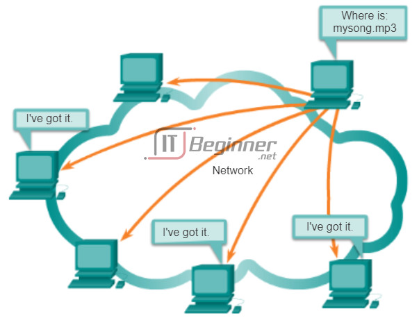
Some P2P applications are based on the Gnutella protocol. They enable people to share files on their hard disks with others. As shown in the figure, Gnutella-compatible client software allows users to connect to Gnutella services over the Internet and to locate and access resources shared by other Gnutella peers. Many client applications are available for accessing the Gnutella network, including BearShare, Gnucleus, LimeWire, Morpheus, WinMX, and XoloX.
While the Gnutella Developer Forum maintains the basic protocol, application vendors often develop extensions to make the protocol work better with their application.
Many P2P applications do not use a central database to record all the files available on the peers. Instead, the devices on the network each tell the others what files are available when queried, and use the file sharing protocol and services to support locating resources.
10.1.2.4 Lab – Researching Peer-to-Peer File Sharing
In this lab, you will complete the following objectives:
- Part 1: Identify P2P Networks, File Sharing Protocols, and Applications
- Part 2: Research P2P File Sharing Issues
- Part 3: Research P2P Copyright Litigations
Lab – Researching Peer-to-Peer File Sharing ./.
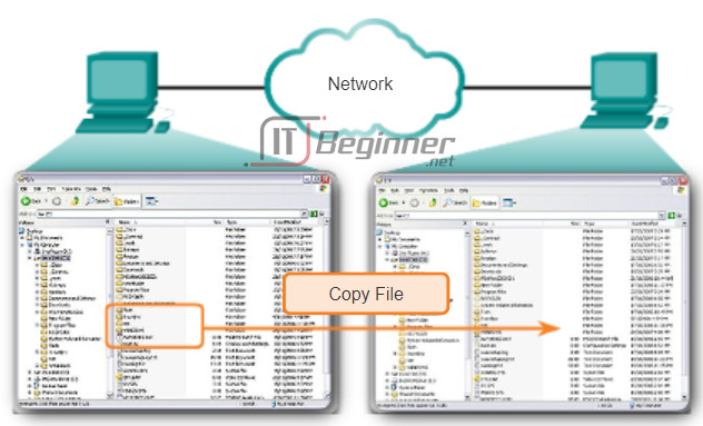
10.1.2.5 Client-Server Model
In the client-server model, the device requesting the information is called a client and the device responding to the request is called a server. Client and server processes are considered to be in the application layer. The client begins the exchange by requesting data from the server, which responds by sending one or more streams of data to the client. Application layer protocols describe the format of the requests and responses between clients and servers. In addition to the actual data transfer, this exchange may also require user authentication and the identification of a data file to be transferred.
One example of a client-server network is using an ISP’s email service to send, receive and store email. The email client on a home computer issues a request to the ISP’s email server for any unread mail. The server responds by sending the requested email to the client.
Although data is typically described as flowing from the server to the client, some data always flows from the client to the server. Data flow may be equal in both directions, or may even be greater in the direction going from the client to the server. For example, a client may transfer a file to the server for storage purposes. As shown in the figure, data transfer from a client to a server is referred to as an upload and data from a server to a client as a download.
[tabs type=”horizontal”]
[tabs_head]
[tab_title]Download[/tab_title]
[tab_title]Upload[/tab_title]
[/tabs_head]
[tab]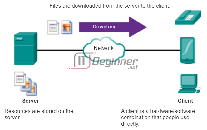 [/tab]
[tab]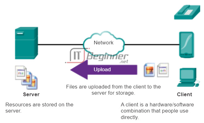 [/tab]
[/tabs]
10.2 Well-Known Application Layer Protocols and Services
10.2.1 Common Application Layer Protocols
10.2.1.1 Application Layer Protocols Revisited
There are dozens of application layer protocols, but on a typical day you probably use only five or six. Three application layer protocols that are involved in everyday work or play are:
- Hypertext Transfer Protocol (HTTP)
- Simple Mail Transfer Protocol (SMTP)
- Post Office Protocol (POP)
These application layer protocols make it possible to browse the web and send and receive email. HTTP is used to enable users to connect to web sites across the Internet. SMTP is used to enable users to send email. And POP is used to enable users to receive email.
The next few pages focus on these three application layer protocols.
10.2.1.2 Hypertext Transfer Protocol and Hypertext Markup Language
When a web address or uniform resource locator (URL) is typed into a web browser, the web browser establishes a connection to the web service running on the server using the HTTP protocol. URLs and Uniform Resource Identifier (URIs) are the names most people associate with web addresses.
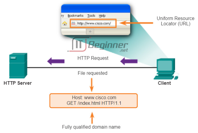
The http://www.cisco.com/index.html URL is an example of a URL that refers to a specific resource; a web page named index.html on a server identified as cisco.com. Click each figure to see the steps used by HTTP.
Web browsers are the type of client application a computer uses to connect to the World Wide Web and access resources stored on a web server. As with most server processes, the web server runs as a background service and makes different types of files available.
To access the content, web clients make connections to the server and request the desired resources. The server replies with the resources and, upon receipt, the browser interprets the data and presents it to the user.
Browsers can interpret and present many data types (such as plain text or Hypertext Markup Language, the language in which web pages are constructed). Other types of data, however, may require another service or program, typically referred to as plug-ins or add-ons. To help the browser determine what type of file it is receiving, the server specifies what kind of data the file contains.
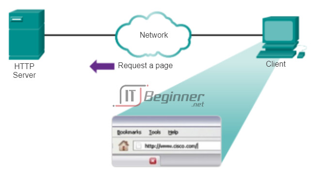
To better understand how the web browser and web client interact, we can examine how a web page is opened in a browser. For this example, use the http://www.cisco.com/index.html URL.
First, as shown in Figure 1, the browser interprets the three parts of the URL:
1. http (the protocol or scheme)
2. www.cisco.com (the server name)
3. index.html (the specific filename requested)
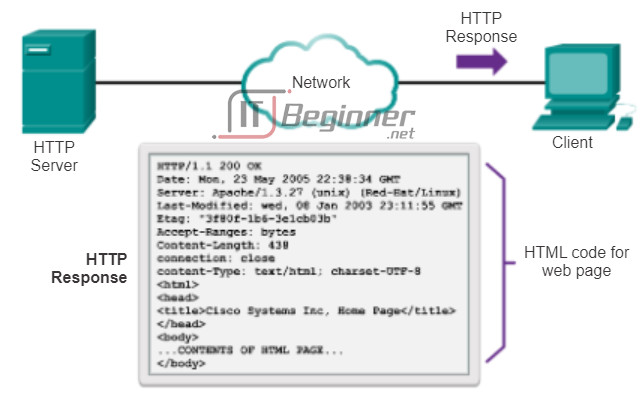
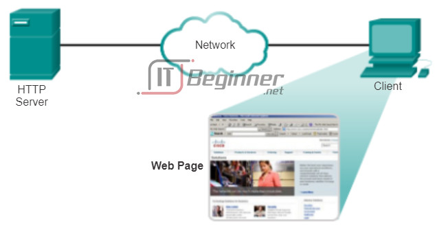
As shown in Figure 2, the browser then checks with a name server to convert www.cisco.com into a numeric address, which it uses to connect to the server. Using HTTP requirements, the browser sends a GET request to the server and asks for the index.html file. The server, as shown in Figure 3, sends the HTML code for this web page to the browser. Finally, as shown in Figure 4, the browser deciphers the HTML code and formats the page for the browser window.
[tabs type=”horizontal”]
[tabs_head]
[tab_title]HTTP Protocol[/tab_title]
[tab_title]HTTP Protocol Step 1[/tab_title]
[tab_title]HTTP Protocol Step 2[/tab_title]
[tab_title]HTTP Protocol Step 3[/tab_title]
[/tabs_head]
[tab]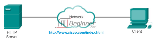 [/tab]
[tab]
[/tab]
[tab]
[/tab]
[tab]
[/tab]
[/tabs]
10.2.1.3 HTTP and HTTPS
HTTP is used across the World Wide Web for data transfer and is one of the most used application protocols today. It was originally developed to simply publish and retrieve HTML pages; however the flexibility of HTTP has made it a vital application within distributed, collaborative information systems.
HTTP is a request/response protocol. When a client, typically a web browser, sends a request to a web server, HTTP specified the message types used for that communication. The three common message types are GET, POST, and PUT (see the figure).
GET is a client request for data. A client (web browser) sends the GET message to the web server to request HTML pages. When the server receives the GET request, it responds with a status line, such as HTTP/1.1 200 OK, and a message of its own. The message from the server may include the requested HTML file, if available, or it may contain an error or information message, such as “The location of the requested file has changed.”
POST and PUT are used to upload data files to the web server. For example, when the user enters data into a form that is embedded within a web page (such as when completing an order request), the POST message is sent to the web server. Included within the POST message is the data that the user submitted in the form.
PUT uploads resources or content to the web server. For example, if a user attempts to upload a file or image to a website, a PUT message is sent from the client to the server with the attached file or image.
Although HTTP is remarkably flexible, it is not a secure protocol. The request messages send information to the server in plain text that can be intercepted and read. Similarly, the server responses, typically HTML pages, are also unencrypted.
For secure communication across the Internet, the HTTP Secure (HTTPS) protocol is used for accessing or posting web server information. HTTPS can use authentication and encryption to secure data as it travels between the client and server. HTTPS specifies additional rules for passing data between the application layer and the transport layer. HTTPS uses the same client request-server response process as HTTP, but the data stream is encrypted with Secure Socket Layer (SSL) before being transported across the network. HTTPS creates additional load and processing time on the server due to the encryption and decryption of traffic.
10.2.1.4 SMTP, POP, and IMAP
One of the primary services offered by an ISP is email hosting. Email has revolutionized how people communicate through its simplicity and speed. Yet to run on a computer or other end device, email requires several applications and services.
Email is a store-and-forward method of sending, storing, and retrieving electronic messages across a network. Email messages are stored in databases on mail servers. ISPs often maintain mail servers that support many different customer accounts.
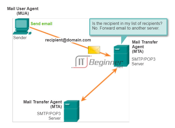
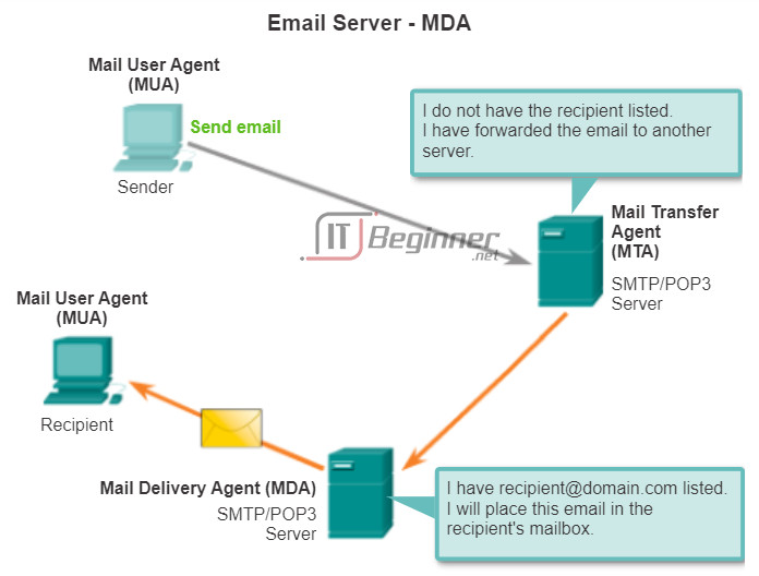
Email clients communicate with mail servers to send and receive email. Mail servers communicate with other mail servers to transport messages from one domain to another. An email client does not communicate directly with another email client when sending email. Instead, both clients rely on the mail server to transport messages. This is true even when both users are in the same domain.
Email clients send messages to the email server configured in the application settings. When the server receives the message, it checks to see if the recipient domain is located on its local database. If it is not, it sends a DNS request to determine the IP address of the mail server for the destination domain. The email is then forwarded to the appropriate server.
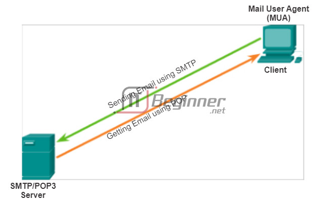
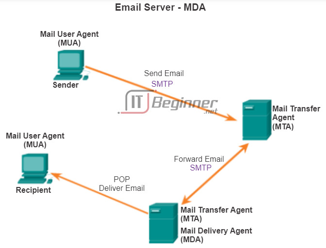
Email supports three separate protocols for operation: Simple Mail Transfer Protocol (SMTP), Post Office Protocol (POP), and Internet Message Access Protocol (IMAP). The application layer process that sends mail, uses SMTP. This is the case if sending from a client to a server, as well as when sending from one server to another.
A client retrieves email, however, using one of two application layer protocols: POP or IMAP.
[tabs type=”horizontal”]
[tabs_head]
[tab_title]Figure 1[/tab_title]
[tab_title]Figure 2[/tab_title]
[/tabs_head]
[tab]
[/tab]
[tab]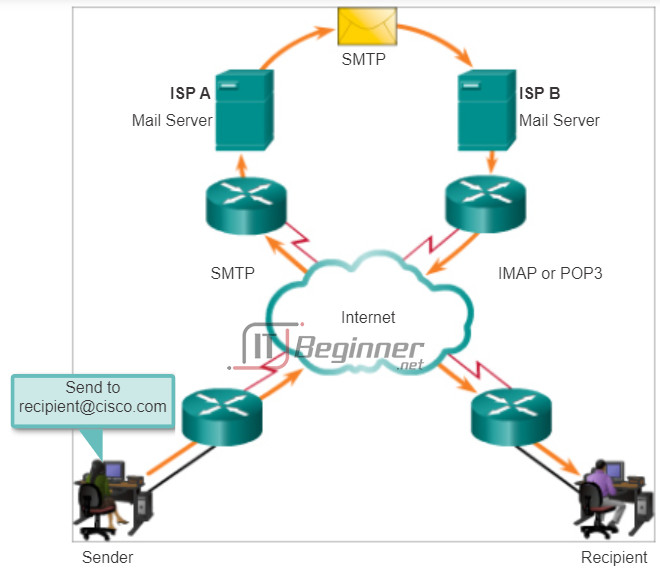 [/tab]
[/tabs]
10.2.1.5 SMTP, POP, and IMAP (cont.)
Simple Mail Transfer Protocol (SMTP) transfers mail reliably and efficiently. For SMTP applications to work properly, the mail message must be formatted properly and SMTP processes must be running on both the client and server.
SMTP message formats require a message header and a message body. While the message body can contain any amount of text, the message header must have a properly formatted recipient email address and a sender address. Any other header information is optional.
When a client sends email, the client SMTP process connects with a server SMTP process on well-known port 25. After the connection is made, the client attempts to send the email to the server across the connection. When the server receives the message, it either places the message in a local account, if the recipient is local, or forwards the message using the same SMTP connection process to another mail server for delivery.
The destination email server may not be online or may be busy when email messages are sent. Therefore, SMTP spools messages to be sent at a later time. Periodically, the server checks the queue for messages and attempts to send them again. If the message is still not delivered after a predetermined expiration time, it is returned to the sender as undeliverable.
10.2.1.6 SMTP, POP, and IMAP (cont.)
Post Office Protocol (POP) enables a workstation to retrieve mail from a mail server. With POP, mail is downloaded from the server to the client and then deleted on the server.
The server starts the POP service by passively listening on TCP port 110 for client connection requests. When a client wants to make use of the service, it sends a request to establish a TCP connection with the server. When the connection is established, the POP server sends a greeting. The client and POP server then exchange commands and responses until the connection is closed or aborted.
Because email messages are downloaded to the client and removed from the server, there is not a centralized location where email messages are kept. Because POP does not store messages, it is undesirable for a small business that needs a centralized backup solution.
POP3 is desirable for an ISP, because it alleviates their responsibility for managing large amounts of storage for their email servers
10.2.1.7 SMTP, POP, and IMAP (cont.)
Internet Message Access Protocol (IMAP) is another protocol that describes a method to retrieve email messages. However, unlike POP, when the user connects to an IMAP-capable server, copies of the messages are downloaded to the client application. The original messages are kept on the server until manually deleted. Users view copies of the messages in their email client software.
Users can create a file hierarchy on the server to organize and store mail. That file structure is duplicated on the email client as well. When a user decides to delete a message, the server synchronizes that action and deletes the message from the server.
For small- to medium-sized businesses, there are many advantages to using IMAP. IMAP can provide long-term storage of email messages on mail servers and allows for centralized backup. It also enables employees to access email messages from multiple locations, using different devices or client software. The mailbox folder structure that a user expects to see is available for viewing regardless of how the user accesses the mailbox.
For an ISP, IMAP may not be the protocol of choice. It can be expensive to purchase and maintain the disk space to support the large number of stored emails. Additionally, if customers expect their mailboxes to be backed up routinely, that can further increase the costs to the ISP.
10.2.1.8 Packet Tracer – Web and Email
In this activity, you will configure HTTP and email services using the simulated server in Packet Tracer. You will then configure clients to access the HTTP and email services.
Packet Tracer – Web and Email Instructions ./.
Packet Tracer – Web and Email – PKA ./.
10.2.2 Providing IP Addressing Services
10.2.2.1 Domain Name Service
In data networks, devices are labeled with numeric IP addresses to send and receive data over networks. Most people cannot remember this numeric address. Domain names were created to convert the numeric address into a simple, recognizable name.
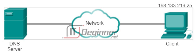
On the Internet, these domain names, such as http://www.cisco.com, are much easier for people to remember than 198.133.219.25, which is the actual numeric address for this server. If Cisco decides to change the numeric address of www.cisco.com, it is transparent to the user, because the domain name remains the same. The new address is simply linked to the existing domain name and connectivity is maintained. When networks were small, it was a simple task to maintain the mapping between domain names and the addresses they represented. As networks have grown and the number of devices increased, this manual system became unworkable.
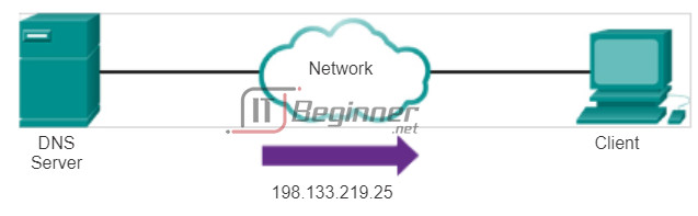
The Domain Name System (DNS) was created for domain name to address resolution for these networks. DNS uses a distributed set of servers to resolve the names associated with these numbered addresses. Click the buttons in the figure to see the steps to resolve DNS addresses.
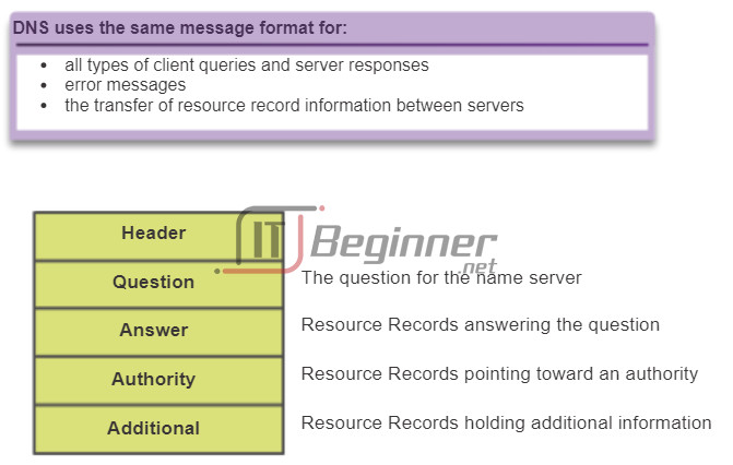
The DNS protocol defines an automated service that matches resource names with the required numeric network address. It includes the format for queries, responses, and data. The DNS protocol communications use a single format called a message. This message format is used for all types of client queries and server responses, error messages, and the transfer of resource record information between servers.
Figures 1 through 5 display the steps involved in DNS resolution.
[tabs type=”horizontal”]
[tabs_head]
[tab_title]Resolving DNS Addresses Step 1[/tab_title]
[tab_title]Resolving DNS Addresses Step 2[/tab_title]
[tab_title]Resolving DNS Addresses Step 3[/tab_title]
[tab_title]Resolving DNS Addresses Step 4[/tab_title]
[tab_title]Resolving DNS Addresses Step 5[/tab_title]
[/tabs_head]
[tab]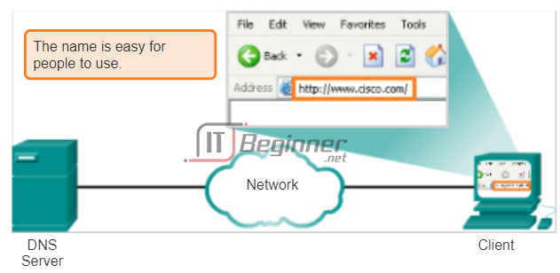 [/tab]
[tab]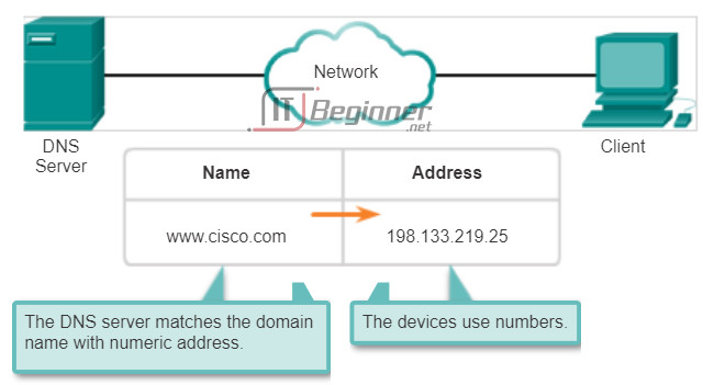 [/tab]
[tab]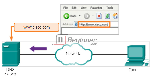 [/tab]
[tab]
[/tab]
[tab]
[/tab]
[/tabs]
10.2.2.2 DNS Message Format
A DNS server provides the name resolution using the Berkeley Internet Name Domain (BIND), or the name daemon, which is often called named (pronounced name-dee). BIND was originally developed by four students at the University of California Berkley in the early 1980s. As shown in the figure, the DNS message format used by BIND is the most widely used DNS format on the Internet.
The DNS server stores different types of resource records used to resolve names. These records contain the name, address, and type of record.
Some of these record types are:
- A – An end device address
- NS – An authoritative name server
- CNAME – The canonical name (or Fully Qualified Domain Name) for an alias; used when multiple services have the single network address, but each service has its own entry in DNS
- MX – Mail exchange record; maps a domain name to a list of mail exchange servers for that domain
When a client makes a query, the server’s BIND process first looks at its own records to resolve the name. If it is unable to resolve the name using its stored records, it contacts other servers to resolve the name.
The request may be passed along to a number of servers, which can take extra time and consume bandwidth. After a match is found and returned to the original requesting server, the server temporarily stores the numbered address that matches the name in cache memory.
If that same name is requested again, the first server can return the address by using the value stored in its name cache. Caching reduces both the DNS query data network traffic and the workloads of servers higher up the hierarchy. The DNS Client service on Windows PCs optimizes the performance of DNS name resolution by also storing previously resolved names in memory. The ipconfig /displaydns command displays all of the cached DNS entries on a Windows computer system.
10.2.2.3 DNS Hierarchy
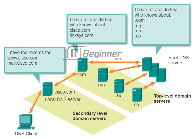
The DNS protocol uses a hierarchical system to create a database to provide name resolution. The hierarchy looks like an inverted tree with the root at the top and branches below (see the figure). DNS uses domain names to form the hierarchy.
The naming structure is broken down into small, manageable zones. Each DNS server maintains a specific database file and is only responsible for managing name-to-IP mappings for that small portion of the entire DNS structure. When a DNS server receives a request for a name translation that is not within its DNS zone, the DNS server forwards the request to another DNS server within the proper zone for translation.
Note: DNS is scalable because hostname resolution is spread across multiple servers.
The different top-level domains represent either the type of organization or the country of origin. Examples of top-level domains are:
- .au – Australia
- .co – Colombia
- .com – a business or industry
- .jp – Japan
- .org – a non-profit organization
After top-level domains are second-level domain names, and below them are other lower level domains. Each domain name is a path down this inverted tree starting from the root. For example, as shown in the figure, the root DNS server may not know exactly where the record for the email server, mail.cisco.com, is located, but it maintains a record for the .com domain within the top-level domain. Likewise, the servers within the .com domain may not have a record for mail.cisco.com, but they do have a record for the domain. The servers within the cisco.com domain have a record (a MX record to be precise) for mail.cisco.com.
DNS relies on this hierarchy of decentralized servers to store and maintain these resource records. The resource records list domain names that the server can resolve and alternative servers that can also process requests. If a given server has resource records that correspond to its level in the domain hierarchy, it is said to be authoritative for those records. For example, a name server in the cisco.netacad.net domain would not be authoritative for the mail.cisco.com record, because that record is held at a higher domain level server; specifically the name server in the cisco.com domain.
10.2.2.4 nslookup
DNS is a client/server service; however, it differs from the other client/server services. While other services use a client that is an application (such as web browser, email client), the DNS client runs as a service itself. The DNS client, sometimes called the DNS resolver, supports name resolution for other network applications and other services that need it.
When configuring a network device, we generally provide one or more DNS Server addresses that the DNS client can use for name resolution. Usually the Internet service provider (ISP) provides the addresses to use for the DNS servers. When a user’s application requests to connect to a remote device by name, the requesting DNS client queries one of these name servers to resolve the name to a numeric address.
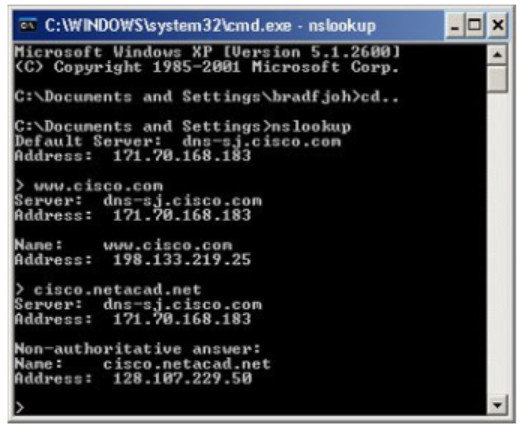
Computer operating systems also have a utility called nslookup that allows the user to manually query the name servers to resolve a given hostname. This utility can also be used to troubleshoot name resolution issues and to verify the current status of the name servers.
In the figure, when the nslookup command is issued, the default DNS server configured for your host is displayed. In this example, the DNS server is dns-sj.cisco.com which has an address of 171.70.168.183.
The name of a host or domain can be entered at the nslookup prompt. In the first query in the figure, a query is made for www.cisco.com. The responding name server provides the address of 198.133.219.25.
The queries shown in the figure are only simple tests. The nslookup utility has many options available for extensive testing and verification of the DNS process. When finished, type exit to leave the nslookup utility.
10.2.2.5 Syntax Checker – DNS CLI Commands in Windows and UNIX
10.2.2.6 Dynamic Host Configuration Protocol
The Dynamic Host Configuration Protocol (DHCP) service enables devices on a network to obtain IP addresses and other information from a DHCP server. This service automates the assignment of IP addresses, subnet masks, gateway, and other IP networking parameters. This is referred to as dynamic addressing. The alternative to dynamic addressing is static addressing. When using static addressing, the network administrator manually enters IP address information on network hosts.
DHCP allows a host to obtain an IP address dynamically when it connects to the network. The DHCP server is contacted and an address requested. The DHCP server chooses an address from a configured range of addresses called a pool and assigns (leases) it to the host for a set period.
On larger local networks, or where the user population changes frequently, DHCP is preferred for address assignment. New users may arrive with laptops and need a connection; others may have new workstations that must be connected. Rather than have the network administrator assign IP addresses for each workstation, it is more efficient to have IP addresses assigned automatically using DHCP.
DHCP-distributed addresses are not permanently assigned to hosts, but are only leased for a period of time. If the host is powered down or taken off the network, the address is returned to the pool for reuse. This is especially helpful with mobile users that come and go on a network. Users can freely move from location to location and re-establish network connections. The host can obtain an IP address after the hardware connection is made, either via a wired or wireless LAN.
DHCP makes it possible to access the Internet using wireless hotspots at airports or coffee shops. When a wireless device enters a hotspot, the device DHCP client contacts the local DHCP server via a wireless connection, and the DHCP server assigns an IP address to the device.
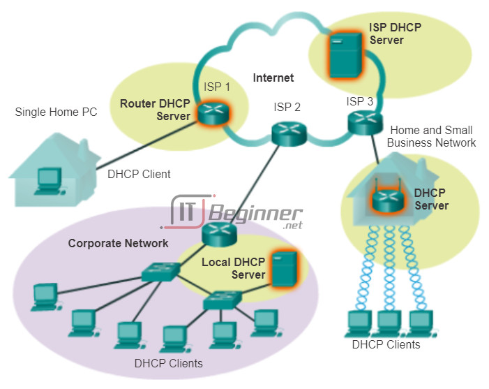
As the figure shows, various types of devices can be DHCP servers when running DHCP service software. The DHCP server in most medium-to-large networks is usually a local dedicated PC-based server. With home networks, the DHCP server is usually located on the local router that connects the home network to the ISP. Local hosts receive IP address information directly from the local router. The local router receives an IP address from the DHCP server at the ISP.
DHCP can pose a security risk because any device connected to the network can receive an address. This risk makes physical security a determining factor of whether to use dynamic or manual addressing. Both dynamic and static addressing have a place in network design. Many networks use both DHCP and static addressing. DHCP is used for general purpose hosts, such as end user devices; static addressing is used for network devices, such as gateways, switches, servers, and printers.
10.2.2.7 DHCP Operation
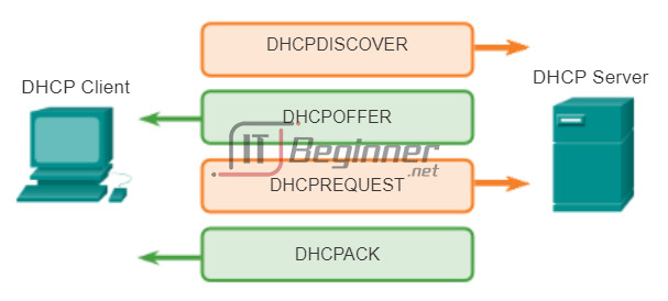
Without DHCP, users have to manually input the IP address, subnet mask, and other network settings to join the network. The DHCP server maintains a pool of IP addresses and leases an address to any DHCP-enabled client when the client is powered on. Because the IP addresses are dynamic (leased), rather than static (permanently assigned), addresses no longer in use are automatically returned to the pool for reallocation. As shown in the figure, when a DHCP-configured device boots up or connects to the network, the client broadcasts a DHCP discover (DHCPDISCOVER) message to identify any available DHCP servers on the network. A DHCP server replies with a DHCP offer (DHCPOFFER) message, which offers a lease to the client. The offer message contains the IP address and subnet mask to be assigned, the IP address of the DNS server, and the IP address of the default gateway. The lease offer also includes the duration of the lease.
The client may receive multiple DHCPOFFER messages if there is more than one DHCP server on the local network; therefore, it must choose between them, and sends a DHCP request (DHCPREQUEST) message that identifies the explicit server and lease offer that the client is accepting. A client may also choose to request an address that it had previously been allocated by the server.
Assuming that the IP address requested by the client, or offered by the server, is still available, the server returns a DHCP acknowledgement (DHCPACK) message that acknowledges to the client that the lease is finalized. If the offer is no longer valid, perhaps due to a timeout or another client taking the lease, then the selected server responds with a DHCP negative acknowledgement (DHCPNAK) message. If a DHCPNAK message is returned, then the selection process must begin again with a new DHCPDISCOVER message being transmitted. After the client has the lease, it must be renewed prior to the lease expiration through another DHCPREQUEST message.
The DHCP server ensures that all IP addresses are unique (the same IP address cannot be assigned to two different network devices simultaneously). Using DHCP enables network administrators to easily reconfigure client IP addresses without having to manually make changes to the clients. Most Internet providers use DHCP to allocate addresses to their customers that do not require a static address.
10.2.2.8 Packet Tracer – DNS and DHCP
In this activity, you will configure and verify static IP addressing and DHCP addressing. You will then configure a DNS server to map IP addresses to the website names.
Packet Tracer – DNS and DHCP Instructions ./.
Packet Tracer – DNS and DHCP – PKA ./.
10.2.2.9 Lab – Observing DNS Resolution
In this lab, you will complete the following objectives:
- Part 1: Observe the DNS Conversion of a URL to an IP Address
- Part 2: Observe DNS Lookup Using the nslookup Command on a Web Site
- Part 3: Observe DNS Lookup Using the nslookup Command on Mail Servers
Lab – Observing DNS Resolution ./.
10.2.3 Providing File Sharing Services
10.2.3.1 File Transfer Protocol
The File Transfer Protocol (FTP) is another commonly used application layer protocol. FTP was developed to allow for data transfers between a client and a server. An FTP client is an application that runs on a computer that is used to push and pull data from a server running an FTP daemon (FTPd).
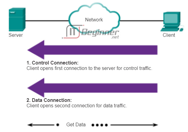
As the figure illustrates, to successfully transfer data, FTP requires two connections between the client and the server, one for commands and replies, the other for the actual file transfer:
- The client establishes the first connection to the server for control traffic, consisting of client commands and server replies.
- The client establishes the second connection to the server for the actual data transfer. This connection is created every time there is data to be transferred.
The data transfer can happen in either direction. The client can download (pull) data from the server or, the client can upload (push) data to the server.
10.2.3.2 Packet Tracer – FTP
In this activity, you will configure FTP services. You will then use the FTP services to transfer files between clients and the server.
Packet Tracer – FTP Instructions ./.
Packet Tracer – FTP – PKA ./.
10.2.3.3 Lab – Exploring FTP
In this lab, you will complete the following objectives:
- Part 1: Use FTP from a Command Prompt
- Part 2: Download an FTP File Using WS_FTP LE
- Part 3: Use FTP in a Browser
Lab – Exploring FTP ./.
10.2.3.4 Server Message Block
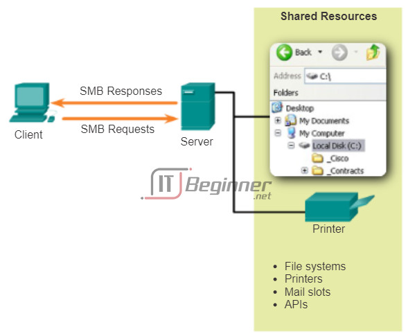
The Server Message Block (SMB) is a client/server file sharing protocol, developed by IBM in the late 1980s, to describe the structure of shared network resources, such as directories, files, printers, and serial ports. It is a request-response protocol.
The SMB protocol describes file system access and how clients can make requests for files. It also describes the SMB protocol interprocess communication. All SMB messages share a common format. This format uses a fixed-sized header, followed by a variable-sized parameter and data component.
SMB messages can:
- Start, authenticate, and terminate sessions
- Control file and printer access
- Allow an application to send or receive messages to or from another device
SMB file-sharing and print services have become the mainstay of Microsoft networking. With the introduction of the Windows 2000 software series, Microsoft changed the underlying structure for using SMB. In previous versions of Microsoft products, the SMB services used a non-TCP/IP protocol to implement name resolution. Beginning with Windows2000, all subsequent Microsoft products use DNS naming, which allows TCP/IP protocols to directly support SMB resource sharing, as shown in Figure 1. The SMB file exchange process between Windows PCs is shown in Figure 2.
Unlike the file sharing supported by File Transfer Protocol (FTP), clients establish a long-term connection to servers. After the connection is established, the user of the client can access the resources on the server as if the resource is local to the client host.
The LINUX and UNIX operating systems also provide a method of sharing resources with Microsoft networks using a version of SMB called SAMBA. The Apple Macintosh operating systems also support resource sharing using the SMB protocol.
[tabs type=”horizontal”]
[tabs_head]
[tab_title]SMB Protocol[/tab_title]
[tab_title]SMB File Sharing[/tab_title]
[/tabs_head]
[tab]
[/tab]
[tab]
[/tab]
[/tabs]
10.3 The Message Heard Around the World
10.3.1 Move It!
10.3.1.1 The Internet of Things
The application layer is responsible for directly accessing the underlying processes that manage and deliver communication through the network. This layer serves as the source and destination of communications across data networks, regardless of the type of data network being used. In fact, advances in how we network are having a direct effect on the type of applications that are being developed.
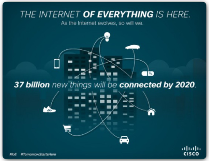
Trends like bring your own device (BYOD), access anywhere, virtualization, and machine-to-machine (m2m) connections have made way to a new breed of applications. It is estimated that approximately 50 billion devices will be connected by 2020. In 2010 alone, more than 350,000 applications were developed with more than three million downloads. All of this leads to a world of intuitive connections between people, processes, data and things on the network.
Using smart-tagging and advanced connectivity to digitize unintelligent products – from bikes and bottles, to refrigerators and cars – and connect them to the Internet, will allow people and companies to interact in new and almost unimaginable ways. Objects will be able to collect, receive and send information to users and other connected objects. As shown in the figure, this new wave in Internet development is known as the Internet of Things!
Over 100 million vending machines, vehicles, smoke alarms, and other devices are already sharing information automatically today, a figure which market analysts at Berg Insight expect to rise to 360 million by 2016. Today, photocopiers with an M2M module can order fresh toner and paper automatically, or alert technicians to a fault – even telling them which parts to bring.
10.3.1.2 Message Travels Through a Network
The massive explosion of applications is due in large part to the genius of the layered approach for processing data through a network. Specifically, keeping the functionality of the application layer separate from the functionality of transporting the data, allows the application layer protocols to be changed and new applications to be developed, without the developer having to worry about the mechanics of getting the data across the network. That is the functionality of other layers and therefore, other developers.
As shown in the figure, when an application sends a request to a server application, the message is built by the application layer, but is then passed down through all the various layer functionalities on the client for delivery. As it moves through the stack each lower layer encapsulates the data with a header that contains the protocols of communication for that layer. These protocols, which are implemented on both the sending and receiving hosts, interact to provide end-to-end delivery of applications over the network.
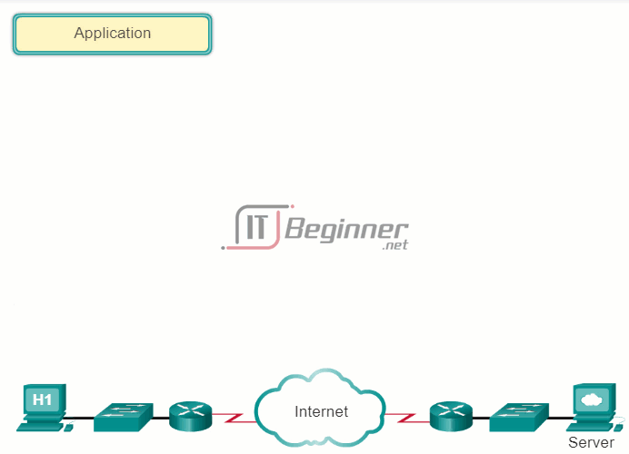
Protocols like HTTP, for example, support the delivery of web pages to end devices. Now that we have learned all the various layers and their functionalities, we can follow a client request of a web page from the web server to see how each of these independent functionalities work fully, together.
Using the TCP/IP model, a complete communication process includes six steps:
Creation of the Data
The first step is the creation of data at the application layer of the originating source end device. In this case, after building the web client’s request, known as an HTTP GET, that data will then be encoded, compressed, and encrypted if necessary. This is the job of the application layer protocol within the TCP/IP model – but this includes the functionality described by the application, presentation, and session layers of the OSI model. The application layer sends this data as a stream to the transport layer.
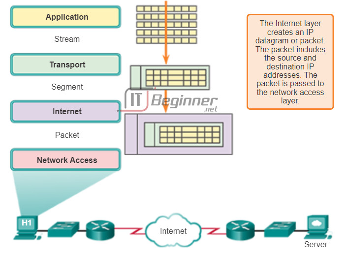
Segmentation and Initial Encapsulation
The next step is segmentation and encapsulation of the data as it passes down the protocol stack. At the transport layer, the HTTP GET message will be broken down into smaller more manageable pieces and each part of the message will have a transport layer header added to it. Inside the transport layer header are indicators on how to rebuild the message. Also included is an identifier, port number 80. This is used to tell the destination server that the message is destined for its web server application. A randomly generated source port is added as well, to ensure that the client can track return communication and forward it up to the correct client application.
10.3.1.3 Getting the Data to the End Device
Addressing
Next, address identifiers are added to the segments, as shown in the figure. Just as there are multiple layers of protocols that prepare the data for transmission to its destination, there are multiple layers of addressing to ensure its delivery. The role of the network layer is to add addressing that allows transfer of the data from the host that originates the data, to the host that uses it. The network layer accomplishes this by encapsulating each segment within an IP packet header. The IP packet header contains the IP addresses of the source and destination devices. (The IP address of the destination device is usually determined through an earlier application process known as domain name service.) The combination of the source and destination IP address, with the source and destination port number, is known as a socket. The socket is used to identify the server and service being requested by the client.
10.3.1.4 Getting the Data through the Internetwork
Preparing for Transportation
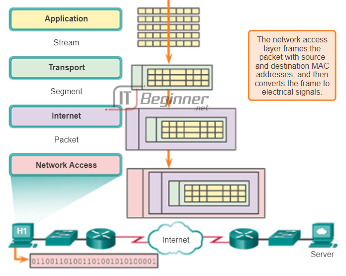
After IP addressing is added, the packet is passed to the network access layer for generation of the data onto the media, as shown in the figure. In order for this to occur, the network access layer must first prepare the packet for transmission by placing it into a frame with a header and trailer. This frame includes the host physical address of the source, as well as the physical address of the next hop on the path to the final destination. This is equivalent to the Layer 2, or data link layer, functionality of the OSI model. Layer 2 is concerned with the delivery of messages on a single local network. The Layer 2 address is unique on the local network and represents the address of the end device on the physical media. In a LAN using Ethernet, this address is called the Media Access Control (MAC) address. Once the network access layer has prepared the frame with source and destination addresses, it then encodes the frame into bits, and then into electrical pulses or flashes of light that are sent across the network media.
Transporting the Data
The data is transported through the internetwork, which consists of media and any intermediate devices. As the encapsulated message is transmitted across the network it may travel across several different media and network types. The network access layer specifies the techniques for getting the frame on and off each medium, otherwise known as the media access control method.
If the destination host is in the same network as the source host, the packet is delivered between the two hosts on the local media without the need for a router. However, if the destination host and source host are not in the same network, the packet may be carried across many networks, on many different media types, and through many routers. As it passes along the network, the information contained within the frame is not altered.
At the boundary of each local network, an intermediate network device, usually a router, de-encapsulate the frame to read the destination host address contained in the header of the packet. Routers use the network identifier portion of this address to determine which path to use to reach the destination host. Once the path is determined, the router encapsulates the packet in a new frame and sends it to the next hop on its way toward the destination end device
10.3.1.5 Getting the Data to the Right Application
Delivering the Data to the Correct Destination Application
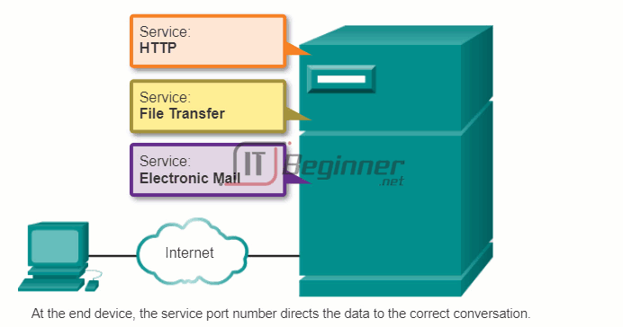
Finally, at the destination end device, the frame is received. De-encapsulate and reassembly of the data occurs, as the data is passed up the stack in the destination device. The data is continually passed up the layers, from the network access layer to the network layer, to the transport layer, until it finally reaches the application layer and can then be processed. But how can the device be sure the correct application process is identified?
As shown in the figure, recall that at the transport layer, information contained in the PDU header identifies the specific process or service running on the destination host device that will act on the data. Hosts, whether they are clients or servers on the Internet, can run multiple network applications simultaneously. People using PCs often have an email client running at the same time as a web browser, an instant messaging program, some streaming media, and perhaps even a game. All these separately running programs are examples of individual processes.
Viewing a web page invokes at least one network process. Clicking a hyperlink causes a web browser to communicate with a web server. At the same time, in the background, an email client may be sending and receiving email, and a colleague or friend may be sending an instant message.
Think about a computer that has only one network interface on it. All the data streams created by the applications that are running on the PC enter and leave through that one interface, yet instant messages do not suddenly appear in the middle of word processor documents, nor do emails show up in the interface of a game.
This is because the individual processes running on the source and destination hosts communicate with each other. Each application or service is represented at Layer 4 by a port number. A unique dialogue between devices is identified with a pair of Layer 4 source and destination port numbers that are representative of the two communicating applications. When the data is received at the host, the port number is examined to determine which application or process is the correct destination for the data.
10.3.1.6 Warriors of the Net
An entertaining resource to help you visualize networking concepts is the animated movie “Warriors of the Net” by TNG Media Lab. Before viewing the video, there are a few things to consider. First, in terms of concepts you have learned in this chapter, think about when in the video you are on the LAN, on WAN, on intranet, on Internet; and what are end devices versus intermediate devices; how the OSI and TCP/IP models apply; what protocols are involved.
Second, while port numbers 21, 23, 25, 53, and 80 are referred to explicitly in the video, IP addresses are referred to only implicitly – can you see where? Where in the video might MAC addresses have been involved?
Finally, though all animations often have simplifications in them, there is one outright error in the video. About 5 minutes in, the statement is made “What happens when Mr. IP doesn’t receive an acknowledgement, he simply sends a replacement packet.” This is not a function of the Layer 3 Internet Protocol, which is an “unreliable”, best effort delivery protocol, but rather a function of the transport layer TCP protocol.
Download the movie from http://www.warriorsofthe.net.
10.4 Summary
10.4.1 Summary
10.4.1.1 Modeling Activity – Make it happen!
Make it happen!
Refer to the modeling activity from the beginning of this chapter as the basis for this activity. Your IP telephones were installed in a half day vs. the full week originally anticipated. Your network has been restored to full capacity and network applications are available for your use. You have the same emails to answer and quotes to write for your manager’s approval.
Use the same scenario you completed in the introduction modeling activity to answer the following questions:
A. Emails
- What method(s) can you use to send email correspondence now that the network is working?
- What format will your emails be sent over the network?
- How can you now send the same message to multiple recipients?
- How can you send the large attachments to multiple recipients using network applications?
- Would using network applications prove to be a cost-effective communication method for your corporation?
B. Quote for Manager’s Approval
- Because you have desktop application programs installed on your computer, will it be relatively easy to produce the quote your manager needs for the new contract due by the end of the week? Explain your answer.
- When you finish writing the quote, how will you present it to your manager for approval? How will he or she send the quote to the client for their approval?
- Is using network applications a cost-effective way to complete business transactions? Justify your answer.
Save a hard copy or an electronic copy of your answers. Be prepared to discuss your answers in class.
Class Activity – Make it happen! Instructions ./.
 Network applications use protocols to facilitate data communication…
- POP
- IMAP
- HTTP
- FTP
…and the list goes on!
10.4.1.2 Packet Tracer Multiuser – Tutorial
The multiuser feature in Packet Tracer allows multiple point-to-point connections between multiple instances of Packet Tracer. This first Packet Tracer Multiuser (PTMU) activity is a quick tutorial demonstrating the steps to establish and verify a multiuser connection to another instance of Packet Tracer within the same LAN. Ideally, this activity is meant for two students. However, it can also be completed as a solo activity simply by opening the two separate files to create two separate instances of Packet Tracer on your local machine.
Packet Tracer Multiuser – Tutorial Instructions ./.
Packet Tracer Multiuser – Tutorial – Client Side – PKA ./.
Packet Tracer Multiuser – Tutorial – Server Side – PKA ./.
10.4.1.3 Packet Tracer Multiuser – Implement Services
In this multiuser activity, two students (players) cooperate to implement and verify services including DHCP, HTTP, Email, DNS and FTP. The server side player will implement and verify services on one server. The client side player will configure two clients and verify access to services.
Packet Tracer Multiuser – Implement Services Instructions ./.
Packet Tracer Multiuser – Implement Services – Client Side – PKA ./.
Packet Tracer Multiuser – Implement Services – Server Side – PKA ./.
10.4.1.4 Summary
The application layer is responsible for directly accessing the underlying processes that manage and deliver communication to the human network. This layer serves as the source and destination of communications across data networks. The application layer applications, services, and protocols enable users to interact with the data network in a way that is meaningful and effective.
- Applications are computer programs with which the user interacts and which initiate the data transfer process at the user’s request.
- Services are background programs that provide the connection between the application layer and the lower layers of the networking model.
- Protocols provide a structure of agreed-upon rules and processes that ensure services running on one particular device can send and receive data from a range of different network devices.
Delivery of data over the network can be requested from a server by a client, or between devices that operate in a P2P arrangement, where the client/server relationship is established, according to which device is the source and destination at that time. Messages are exchanged between the application layer services at each end device in accordance with the protocol specifications to establish and use these relationships.
Protocols like HTTP, for example, support the delivery of web pages to end devices. SMTP and POP support sending and receiving email. SMB and FTP enable users to share files. P2P applications make it easier for consumers to seamlessly share media in a distributed fashion. DNS resolves the human legible names used to refer to network resources into numeric addresses usable by the network. Clouds are remote upstream locations that store data and host applications so that users do not require as many local resources, and so that users can seamlessly access content on different devices from any location.
All of these elements work together, at the application layer. The application layer enables users to work and play over the Internet.