Introduction to Networks Instructor Materials – Chapter 11: It’s a Network
11.0 It’s a Network
11.0.1 Introduction
11.0.1.1 Introduction
Up to this point in the course, we have considered the services that a data network can provide to the human network, examined the features of each layer of the OSI model and the operations of TCP/IP protocols, and looked in detail at Ethernet, a universal LAN technology. The next step is to learn how to assemble these elements together in a functioning network that can be maintained.
Upon completion of this chapter you will be able to:
- Identify the devices and protocols used in a small network.
- Explain how a small network serves as the basis of larger networks.
- Describe the need for basic security measures on network devices.
- Identify security vulnerabilities and general mitigation techniques.
- Configure network devices with device hardening features to mitigate security threats.
- Use the output of the ping and tracert commands to establish relative network performance.
- Use basic show commands to verify the configuration and status of a device interface.
- Use the basic host and IOS commands to acquire information about the devices in a network.
- Explain file systems on routers and switches.
- Apply the commands to back up and restore and IOS configuration file.
11.0.1.2 Activity – Did You Notice…?
Did You Notice…?
Note: Students can work singularly, in pairs, or the full classroom can complete this activity together.
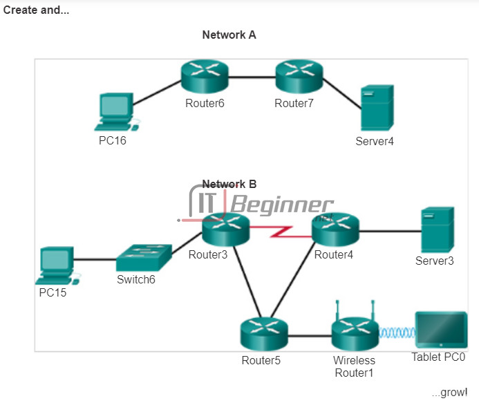
Take a look at the two networks in the diagram. Visually compare and contrast the two networks. Make note of the devices used in each network design. Since the devices are labeled, you already know what types of end devices and intermediate devices are on each network.
But how are the two networks different? Is it just that there are more devices present on Network B than on Network A?
Select the network you would use if you owned a small to medium-sized business. Be able to justify your selected network based on cost, speed, ports, expandability, and manageability.
Class Activity – Did You Notice Instructions ./.
11.1 Create and Grow
11.1.1 Devices in a Small Network
11.1.1.1 Small Network Topologies
The majority of businesses are small businesses. It is not surprising then that the majority of networks are small networks.
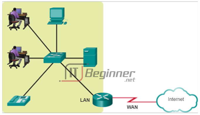
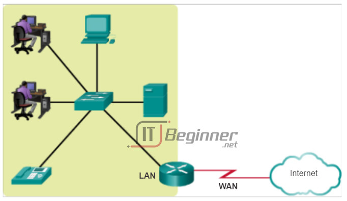
With small networks, the design of the network is usually simple. The number and type of devices on the network are significantly reduced compared to that of a larger network. The network topologies for small networks typically involve a single router and one or more switches. Small networks may also have wireless access points (possibly built into the router) and IP phones. As for connection to the Internet, normally a small network has a single WAN connection provided by DSL, cable, or an Ethernet connection.
Managing a small network requires many of the same skills as those required for managing a larger one. The majority of work is focused on maintenance and troubleshooting of existing equipment, as well as securing devices and information on the network. The management of a small network is either done by an employee of the company or a person contracted by the company, depending on the size of the business and the type of business.
A typical small-business network is shown in the figure.
11.1.1.2 Device Selection for a Small Network
In order to meet user requirements, even small networks require planning and design. Planning ensures that all requirements, cost factors, and deployment options are given due consideration.
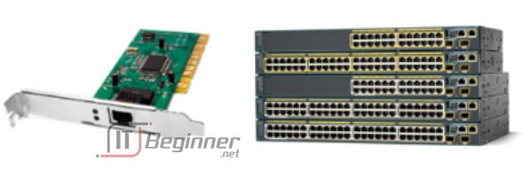
One of the first design considerations when implementing a small network is the type of intermediate devices to use to support the network. When selecting the type of intermediate devices, there are a number of factors that need to be considered, as shown in the figure.
Cost
Cost is typically one of the most important factors when selecting equipment for a small business network. The cost of a switch or router is determined by its capacity and features. The device capacity includes the number and types of ports available and the backplane speed. Other factors that impact the cost are network management capabilities, embedded security technologies, and optional advanced switching technologies. The expense of cable runs required to connect every device on the network must also be considered. Another key element affecting cost consideration is how much redundancy to incorporate into the network – this includes devices, ports per device, and copper or fiber-optic cabling.
Speed and Types of Ports/Interfaces
Choosing the number and type of ports on a router or switch is a critical decision. Questions to be asked include: “Do we order just enough ports for today’s needs, or do we consider growth requirements?”, “Do we require a mixture of UTP speeds?”, and “Do we require both UTP and fiber ports?”
Newer computers have built-in 1 Gbps NICs. 10 Gbps ports are already included with some workstations and servers. While it is more expensive, choosing Layer 2 devices that can accommodate increased speeds allows the network to evolve without replacing central devices.
Expandability
Networking devices come in both fixed and modular physical configurations. Fixed configurations have a specific number and type of ports or interfaces. Modular devices have expansion slots that provide the flexibility to add new modules as requirements evolve. Most modular devices come with a basic number of fixed ports as well as expansion slots. Switches are available with special additional ports for optional high-speed uplinks. Also, because routers can be used for connecting different numbers and types of networks, care must be taken to select the appropriate modules and interfaces for the specific media. Questions to be considered include: “Do we order devices with upgradable modules?”, and “What type of WAN interfaces, if any, are required on the router(s)?”
Operating System Features and Services
Depending on the version of the operating system, a network device can support certain features and services, such as:
- Security
- QoS
- VoIP
- Layer 3 switching
- NAT
- DHCP
Routers can be expensive based on interfaces and features needed. Additional modules, such as fiber-optics, increase the cost of the network devices.

11.1.1.3 IP Addressing for a Small Network
When implementing a small network, it is necessary to plan the IP addressing space. All hosts within an internetwork must have a unique address. Even on a small network, address assignment within the network should not be random. Rather the IP addressing scheme should be planned, documented and maintained based on the type of device receiving the address.
Examples of different types of devices that will factor into the IP design are:
- End devices for users
- Servers and peripherals
- Hosts that are accessible from the Internet
- Intermediary devices
Planning and documenting the IP addressing scheme helps the administrator to track device types. For example, if all servers are assigned a host address between ranges of 50-100, it is easy to identify server traffic by IP address. This can be very useful when troubleshooting network traffic issues using a protocol analyzer.
Additionally, administrators are better able to control access to resources on the network based on IP address when a deterministic IP addressing scheme is used. This can be especially important for hosts that provide resources to the internal network as well as to the external network. Web servers or e-commerce servers play such a role. If the addresses for these resources are not planned and documented, the security and accessibility of the devices are not easily controlled. If a server has a random address assigned, blocking access to this address is difficult and clients may not be able to locate this resource.
Each of these different device types should be allocated to a logical block of addresses within the address range of the network.
Click the buttons in the figure to see the method for assignment.
11.1.1.4 Redundancy in a Small Network
Another important part of network design is reliability. Even small businesses often rely on their network heavily for business operation. A failure of the network can be very costly. In order to maintain a high degree of reliability, redundancy is required in the network design. Redundancy helps to eliminate single points of failure. There are many ways to accomplish redundancy in a network. Redundancy can be accomplished by installing duplicate equipment, but it can also be accomplished by supplying duplicate network links for critical areas, as shown in the figure.
The smaller the network, the less the chance that redundancy of equipment will be affordable. Therefore, a common way to introduce redundancy is through the use of redundant switch connections between multiple switches on the network and between switches and routers.
Also, servers often have multiple NIC ports that enable redundant connections to one or more switches. In a small network, servers typically are deployed as web servers, file servers, or email servers.
Small networks typically provide a single exit point toward the Internet via one or more default gateways. With one router in the topology, the only redundancy in terms of Layer 3 paths is enabled by utilizing more than one inside Ethernet interface on the router. However, if the router fails, the entire network loses connectivity to the Internet. For this reason, it may be advisable for a small business to pay for a least-cost option account with a second service provider for backup.
11.1.1.5 Design Considerations for a Small Network
Users expect immediate access to their emails and to the files that they are sharing or updating. To help ensure this availability, the network designer should take the following steps:
Step 1. Secure file and mail servers in a centralized location.
Step 2. Protect the location from unauthorized access by implementing physical and logical security measures.
Step 3. Create redundancy in the server farm that ensures if one device fails, files are not lost.
Step 4. Configure redundant paths to the servers.
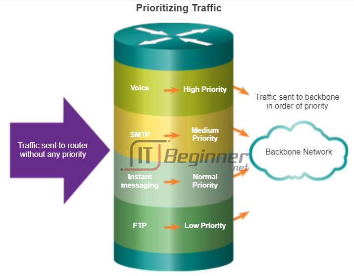
In addition, modern networks often use some form of voice or video over IP for communication with customers and business partners. This type of converged network is implemented as an integrated solution or as an additional form of raw data overlaid onto the IP network. The network administrator should consider the various types of traffic and their treatment in the network design. The router(s) and switch(es) in a small network should be configured to support real-time traffic, such as voice and video, in a distinct manner relative to other data traffic. In fact, a good network design will classify traffic carefully according to priority, as shown in the figure. Traffic classes could be as specific as:
- File transfer
- Voice
- Video
- Messaging
- Transactional
In the end, the goal for a good network design, even for a small network, is to enhance productivity of the employees and minimize network downtime.
11.1.1.6 Identifying Devices in a Small Network
11.1.2 Protocols in a Small Network
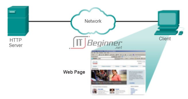
11.1.2.1 Common Applications in a Small Network
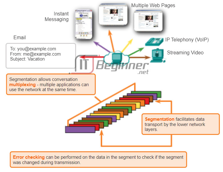
The network is only as useful as the applications that are on it. As shown in the figure, within the application layer, there are two forms of software programs or processes that provide access to the network: network applications and application layer services.
Network Applications
Applications are the software programs used to communicate over the network. Some end-user applications are network-aware, meaning that they implement application layer protocols and are able to communicate directly with the lower layers of the protocol stack. Email clients and web browsers are examples of this type of application.
Application Layer Services
Other programs may need the assistance of application layer services to use network resources, like file transfer or network print spooling. Though transparent to an employee, these services are the programs that interface with the network and prepare the data for transfer. Different types of data, whether text, graphics, or video, require different network services to ensure that they are properly prepared for processing by the functions occurring at the lower layers of the OSI model.
Each application or network service uses protocols, which define the standards and data formats to be used. Without protocols, the data network would not have a common way to format and direct data. In order to understand the function of various network services, it is necessary to become familiar with the underlying protocols that govern their operation.
11.1.2.2 Common Protocols in a Small Network
Most of a technician’s work, in either a small or a large network, will in some way be involved with network protocols. Network protocols support the applications and services used by employees in a small network. Common network protocols include:
- DNS
- Telnet
- IMAP, SMTP, POP (email)
- DHCP
- HTTP
- FTP
Click the servers in the figure for a brief description of the network services each provides.
These network protocols comprise the fundamental tool set of a network professional. Each of these network protocols defines:
- Processes on either end of a communication session
- Types of messages
- Syntax of the messages
- Meaning of informational fields
- How messages are sent and the expected response
- Interaction with the next lower layer
Many companies have established a policy of using secure versions of these protocols whenever possible. These protocols are HTTPS, SFTP, and SSH.
11.1.2.3 Real-Time Applications for a Small Network
In addition to the common network protocols described previously, modern businesses, even small ones, typically utilize real-time applications for communicating with customers and business partners. While a small company may not be able to justify the cost of an enterprise Cisco Telepresence solution, there are other real-time applications, as shown in Figure 1, that are affordable and justifiable for small business organizations. Real-time applications require more planning and dedicated services (relative to other types of data) to ensure priority delivery of voice and video traffic. This means that the network administrator must ensure the proper equipment is installed in the network and that the network devices are configured to ensure priority delivery. Figure 2 shows elements of a small network that support real-time applications.
Infrastructure
To support the existing and proposed real-time applications, the infrastructure must accommodate the characteristics of each type of traffic. The network designer must determine whether the existing switches and cabling can support the traffic that will be added to the network. Cabling that can support gigabit transmissions should be able to carry the traffic generated and not require any changes to the infrastructure. Older switches may not support Power over Ethernet (PoE). Obsolete cabling may not support the bandwidth requirements. The switches and cabling would need to be upgraded to support these applications.
VoIP
VoIP is implemented in an organization that still uses traditional telephones. VoIP uses voice-enabled routers. These routers convert analog voice from traditional telephone signals into IP packets. After the signals are converted into IP packets, the router sends those packets between corresponding locations. VoIP is much less expensive than an integrated IP telephony solution, but the quality of communications does not meet the same standards. Voice and video over IP solutions for small businesses can be realized, for example, with Skype and non-enterprise versions of Cisco WebEx.
IP Telephony
In IP telephony, the IP phone itself performs voice-to-IP conversion. Voice-enabled routers are not required within a network with an integrated IP telephony solution. IP phones use a dedicated server for call control and signaling. There are now many vendors with dedicated IP telephony solutions for small networks.
Real-time Applications
To transport streaming media effectively, the network must be able to support applications that require delay-sensitive delivery. Real-Time Transport Protocol (RTP) and Real-Time Transport Control Protocol (RTCP) are two protocols that support this requirement. RTP and RTCP enable control and scalability of the network resources by allowing quality of service (QoS) mechanisms to be incorporated. These QoS mechanisms provide valuable tools for minimizing latency issues for real-time streaming applications.
[tabs type=”horizontal”]
[tabs_head]
[tab_title]Employee Productivity with Real-Time Applications[/tab_title]
[tab_title]Behind the Scenes[/tab_title]
[/tabs_head]
[tab] [/tab]
[tab]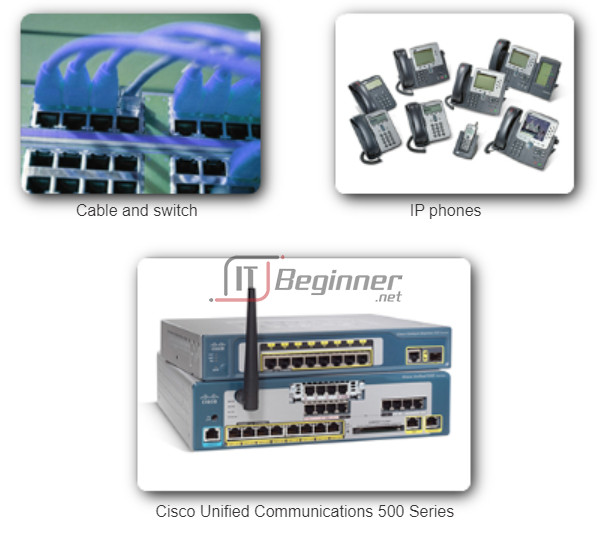 [/tab]
[/tabs]
11.1.3 Growing to Larger Networks
11.1.3.1 Scaling a Small Network
Growth is a natural process for many small businesses, and their networks must grow accordingly. A network administrator for a small network will either work reactively or proactively, depending on the leaders of the company, which often include the network administrator. Ideally, the network administrator has enough lead time to make intelligent decisions about growing the network in-line with the growth of the company.
To scale a network, several elements are required:
- Network documentation – physical and logical topology
- Device inventory – list of devices that use or comprise the network
- Budget – itemized IT budget, including fiscal year equipment purchasing budget
- Traffic analysis – protocols, applications, and services and their respective traffic requirements should be documented
These elements are used to inform the decision-making that accompanies the scaling of a small network.

11.1.3.2 Protocol Analysis of a Small Network
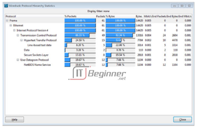
Supporting and growing a small network requires being familiar with the protocols and network applications running over the network. While the network administrator will have more time in a small network environment to individually analyze network utilization for each network-enabled device, a more holistic approach with some type of software- or hardware-based protocol analyzer is recommended.
As shown in the figure, protocol analyzers enable a network professional to quickly compile statistical information about traffic flows on a network.
When trying to determine how to manage network traffic, especially as the network grows, it is important to understand the type of traffic that is crossing the network as well as the current traffic flow. If the types of traffic are unknown, the protocol analyzer will help identify the traffic and its source.
To determine traffic flow patterns, it is important to:
- Capture traffic during peak utilization times to get a good representation of the different traffic types.
- Perform the capture on different network segments, because some traffic will be local to a particular segment.
Information gathered by the protocol analyzer is analyzed based on the source and destination of the traffic as well as the type of traffic being sent. This analysis can be used to make decisions on how to manage the traffic more efficiently. This can be done by reducing unnecessary traffic flows or changing flow patterns altogether by moving a server, for example.
Sometimes, simply relocating a server or service to another network segment improves network performance and accommodates the growing traffic needs. At other times, optimizing the network performance requires major network redesign and intervention.
11.1.3.3 Evolving Protocol Requirements
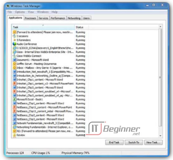
In addition to understanding changing traffic trends, a network administrator must also be aware of how network use is changing. As shown in the figure, a network administrator in a small network has the ability to obtain in-person IT “snapshots” of employee application utilization for a significant portion of the employee workforce over time. These snapshots typically include information such as:
- OS + OS Version
- Non-Network Applications
- Network Applications
- CPU Utilization
- Drive Utilization
- RAM Utilization
Documenting snapshots for employees in a small network over a period of time will go a long way toward informing the network administrator of evolving protocol requirements and associated traffic flows. For example, it may be that some employees are using off-site resources such as social media in order to better position a company with respect to marketing. When they began working for the company, these employees may have focused less on Internet-based advertising. This shift in resource utilization may require the network administrator to shift network resource allocations accordingly.
It is the responsibility of the network administrator to track network utilization and traffic flow requirements, and implement network modifications in order to optimize employee productivity as the network and business grow.
11.2 Keeping the Network Safe
11.2.1 Network Device Security Measures
11.2.1.1 Categories of Threats to Network Security
Whether wired or wireless, computer networks are essential to everyday activities. Individuals and organizations alike depend on their computers and networks. Intrusion by an unauthorized person can result in costly network outages and loss of work. Attacks to a network can be devastating and can result in a loss of time and money due to damage or theft of important information or assets.
Intruders can gain access to a network through software vulnerabilities, hardware attacks or through guessing someone’s username and password. Intruders who gain access by modifying software or exploiting software vulnerabilities are often called hackers.
After the hacker gains access to the network, four types of threats may arise:
- Information theft
- Identity theft
- Data loss/manipulation
- Disruption of service
Click the images in the figure to see more information.
Even in small networks, it is necessary to consider security threats and vulnerabilities when planning a network implementation.
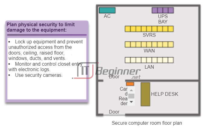
11.2.1.2 Physical Security
When you think of network security, or even computer security, you may imagine attackers exploiting software vulnerabilities. An equally important vulnerability is the physical security of devices, as shown in the figure. An attacker can deny the use of network resources if those resources can be physically compromised.
The four classes of physical threats are:
- Hardware threats – physical damage to servers, routers, switches, cabling plant, and workstations
- Environmental threats – temperature extremes (too hot or too cold) or humidity extremes (too wet or too dry)
- Electrical threats – voltage spikes, insufficient supply voltage (brownouts), unconditioned power (noise), and total power loss
- Maintenance threats – poor handling of key electrical components (electrostatic discharge), lack of critical spare parts, poor cabling, and poor labeling
Some of these issues must be dealt with in an organizational policy. Some of them are subject to good leadership and management in the organization.
11.2.1.3 Types of Security Vulnerabilities
Three network security factors are vulnerability, threat, and attack.
Vulnerability is the degree of weakness which is inherent in every network and device. This includes routers, switches, desktops, servers, and even security devices.
Threats include the people interested and qualified in taking advantage of each security weakness. Such individuals can be expected to continually search for new exploits and weaknesses.
Threats are realized by a variety of tools, scripts, and programs to launch attacks against networks and network devices. Typically, the network devices under attack are the endpoints, such as servers and desktop computers.
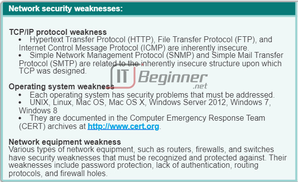
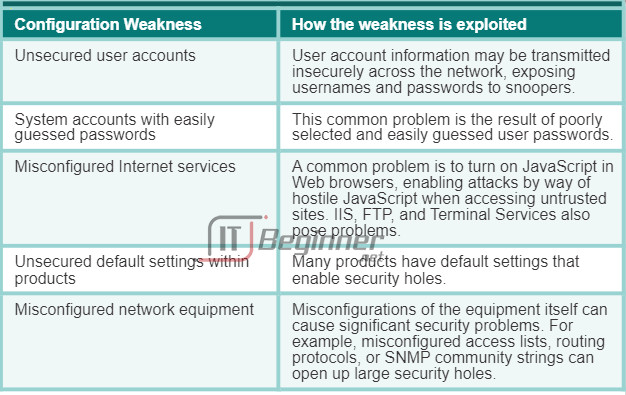
There are three primary vulnerabilities or weaknesses:
- Technological, as shown in Figure 1
- Configuration, as shown in Figure 2
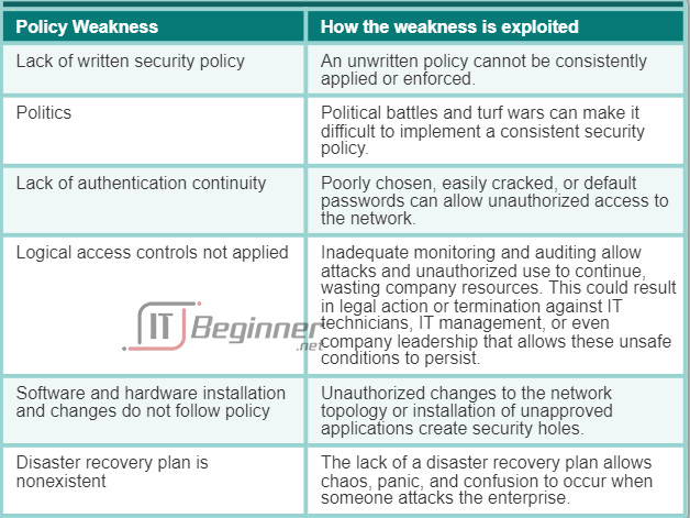
- Security policy, as shown in Figure 3
All three of these vulnerabilities or weaknesses can lead to various attacks, including malicious code attacks and network attacks.
[tabs type=”horizontal”]
[tabs_head]
[tab_title]Figure 1[/tab_title]
[tab_title]Figure 2[/tab_title]
[tab_title]Figure 3[/tab_title]
[/tabs_head]
[tab]
[/tab]
[tab]
[/tab]
[tab]
[/tab]
[/tabs]
11.2.1.4 Activity – Security Threats and Vulnerabilities
11.2.2 Vulnerabilities and Network Attacks
11.2.2.1 Viruses, Worms, and Trojan Horses
Malicious code attacks include a number of types of computer programs that were created with the intention of causing data loss or damage. The three main types of malicious code attacks are viruses, Trojan horses, and worms.
A virus is malicious software that is attached to another program to execute a particular unwanted function on a workstation. An example is a program that is attached to command.com (the primary interpreter for Windows systems) and deletes certain files and infects any other versions of command.com that it can find.
A Trojan horse is different only in that the entire application was written to look like something else, when in fact it is an attack tool. An example of a Trojan horse is a software application that runs a simple game on a workstation. While the user is occupied with the game, the Trojan horse mails a copy of itself to every address in the user’s address book. The other users receive the game and play it, thereby spreading the Trojan horse to the addresses in each address book.
Viruses normally require a delivery mechanism, a vector, such as a zip file or some other executable file attached to an email, to carry the virus code from one system to another. The key element that distinguishes a computer worm from a computer virus is that human interaction is required to facilitate the spread of a virus.
Worms are self-contained programs that attack a system and try to exploit a specific vulnerability in the target. Upon successful exploitation of the vulnerability, the worm copies its program from the attacking host to the newly exploited system to begin the cycle again. The anatomy of a worm attack is as follows:
- The enabling vulnerability – A worm installs itself by exploiting known vulnerabilities in systems, such as naive end users who opens unverified executable attachments in emails.
- Propagation mechanism – After gaining access to a host, a worm copies itself to that host and then selects new targets.
- Payload – After a host is infected with a worm, the attacker has access to the host, often as a privileged user. Attackers could use a local exploit to escalate their privilege level to administrator.
11.2.2.2 Reconnaissance Attacks
In addition to malicious code attacks, it is also possible for networks to fall prey to various network attacks. Network attacks can be classified into three major categories:
- Reconnaissance attacks – the unauthorized discovery and mapping of systems, services, or vulnerabilities
- Access attacks – the unauthorized manipulation of data, system access, or user privileges
- Denial of service – the disabling or corruption of networks, systems, or services
Reconnaissance Attacks
External attackers can use Internet tools, such as the nslookup and whois utilities, to easily determine the IP address space assigned to a given corporation or entity. After the IP address space is determined, an attacker can then ping the publicly available IP addresses to identify the addresses that are active. To help automate this step, an attacker may use a ping sweep tool, such as fping or gping, which systematically pings all network addresses in a given range or subnet. This is similar to going through a section of a telephone book and calling each number to see who answers.
Click each type of reconnaissance attack tool to see an animation of the attack.
11.2.2.3 Access Attacks
Access attacks exploit known vulnerabilities in authentication services, FTP services, and web services to gain entry to web accounts, confidential databases, and other sensitive information. An access attack allows an individual to gain unauthorized access to information that they have no right to view. Access attacks can be classified into four types. One of the most common types of access attacks is the password attack. Password attacks can be implemented using a packet sniffer to yield user accounts and passwords that are transmitted as clear text. Password attacks can also refer to repeated attempts to log in to a shared resource, such as a server or router, to identify a user account, password, or both. These repeated attempts are called dictionary attacks or brute-force attacks.
Click the buttons in the figure to see examples of access attacks.
[tabs type=”horizontal”]
[tabs_head]
[tab_title]Password Attack[/tab_title]
[tab_title]Trust Exploitation[/tab_title]
[tab_title]Port Redirection[/tab_title]
[tab_title]Man-in-the-Middle[/tab_title]
[/tabs_head]
[tab]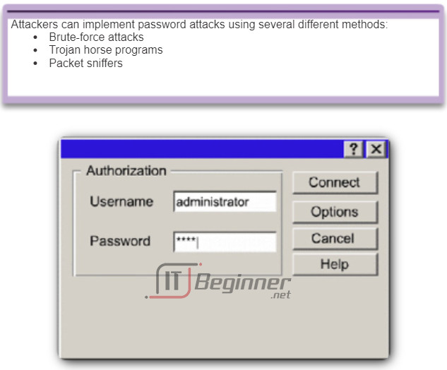 [/tab]
[tab] [/tab]
[tab]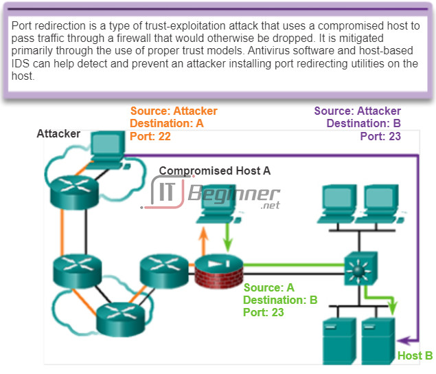 [/tab]
[tab]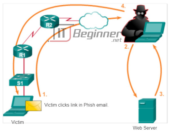 [/tab]
[/tabs]
11.2.2.4 DoS Attacks
Denial of Service
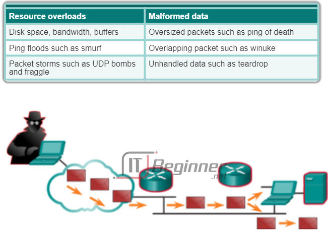
DoS attacks are the most publicized form of attack and also among the most difficult to eliminate. Even within the attacker community, DoS attacks are regarded as trivial and considered bad form, because they require so little effort to execute. But because of their ease of implementation and potentially significant damage, DoS attacks deserve special attention from security administrators.
DoS attacks take many forms. Ultimately, they prevent authorized people from using a service by consuming system resources.
Click the buttons in the figure to see examples of DoS and DDoS attacks.
[tabs type=”horizontal”]
[tabs_head]
[tab_title]DoS Attack[/tab_title]
[tab_title]Ping of Death[/tab_title]
[tab_title]SYN Flood[/tab_title]
[tab_title]DDoS[/tab_title]
[tab_title]Smurf Attack[/tab_title]
[/tabs_head]
[tab]
[/tab]
[tab] [/tab]
[tab]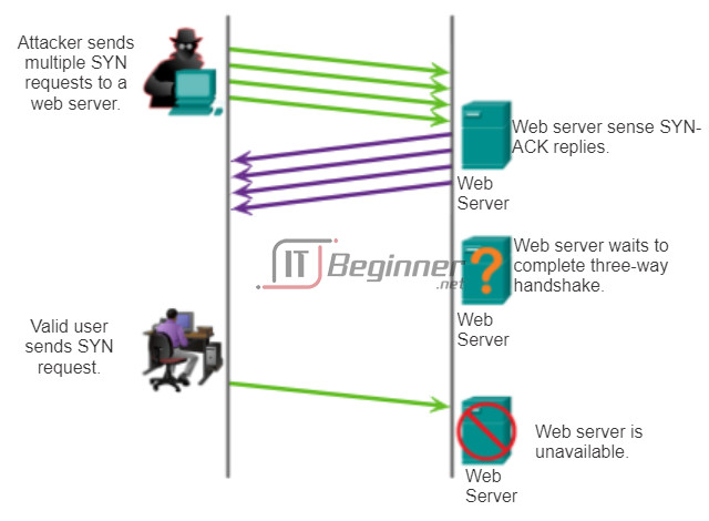 [/tab]
[tab]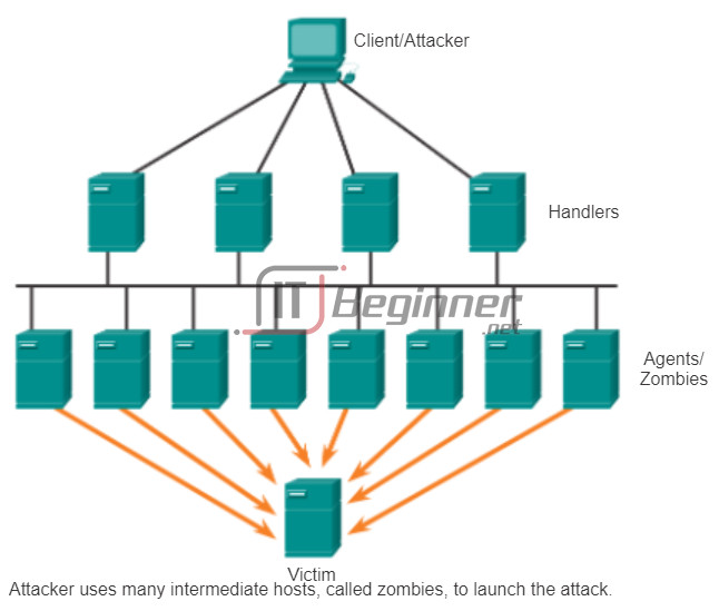 [/tab]
[tab]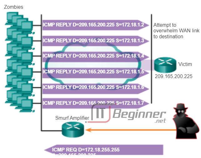 [/tab]
[/tabs]
11.2.2.5 Activity – Types of Attack
11.2.2.6 Lab – Researching Network Security Threats
In this lab, you will complete the following objectives:
- Part 1: Explore the SANS Website
- Part 2: Identify Recent Network Security Threats
- Part 3: Detail a Specific Network Security Threat
Lab – Researching Network Security Threats ./.
11.2.3 Mitigating Network Attacks
11.2.3.1 Backup, Upgrade, Update, and Patch
Antivirus software can detect most viruses and many Trojan horse applications and prevent them from spreading in the network. Antivirus software can be deployed at the user level and at the network level.
Keeping up to date with the latest developments in these sorts of attacks can also lead to a more effective defense against these attacks. As new virus or Trojan applications are released, enterprises need to keep current with the latest versions of antivirus software as well.
Worm attack mitigation requires diligence on the part of system and network administration staff. The following are the recommended steps for worm attack mitigation:
- Containment – Contain the spread of the worm within the network. Compartmentalize uninfected parts of the network.
- Inoculation – Start patching all systems and, if possible, scanning for vulnerable systems.
- Quarantine – Track down each infected machine inside the network. Disconnect, remove, or block infected machines from the network.
- Treatment – Clean and patch each infected system. Some worms may require complete core system reinstallations to clean the system.
The most effective way to mitigate a worm attack is to download security updates from the operating system vendor and patch all vulnerable systems. This is difficult with uncontrolled user systems in the local network. Administering numerous systems involves the creation of a standard software image (operating system and accredited applications that are authorized for use on client systems) that is deployed on new or upgraded systems. However, security requirements change and already deployed systems may need to have updated security patches installed.
One solution to the management of critical security patches is to create a central patch server that all systems must communicate with after a set period of time, as shown in the figure. Any patches that are not applied to a host are automatically downloaded from the patch server and installed without user intervention.
11.2.3.2 Authentication, Authorization, and Accounting
Authentication, authorization, and accounting (AAA, or “triple A”) network security services provide the primary framework to set up access control on a network device. AAA is a way to control who is permitted to access a network (authenticate), what they can do while they are there (authorize), and to watch the actions they perform while accessing the network (accounting). AAA provides a higher degree of scalability than the console, AUX, VTY, and privileged EXEC authentication commands alone.
Authentication
Users and administrators must prove that they are who they say they are. Authentication can be established using username and password combinations, challenge and response questions, token cards, and other methods. For example: “I am user ‘student’. I know the password to prove that I am user ‘student’.”
In a small network, local authentication is often used. With local authentication, each device maintains its own database of username/password combinations. However, when there are more than a few user accounts in a local device database, managing those user accounts becomes complex. Additionally, as the network grows and more devices are added to the network, local authentication becomes difficult to maintain and does not scale. For example, if there are 100 network devices, all user accounts must be added to all 100 devices.
For larger networks, a more scalable solution is external authentication. External authentication allows all users to be authenticated through an external network server. The two most popular options for external authentication of users are RADIUS and TACACS+:
- RADIUS is an open standard with low use of CPU resources and memory. It is used by a range of network devices, such as switches, routers, and wireless devices.
- TACACS+ is a security mechanism that enables modular authentication, authorization, and accounting services. It uses a TACACS+ daemon running on a security server.
Authorization
After the user is authenticated, authorization services determine which resources the user can access and which operations the user is allowed to perform. An example is, “User ‘student’ can access host serverXYZ using Telnet only.”
Accounting
Accounting records what the user does, including what is accessed, the amount of time the resource is accessed, and any changes that were made. Accounting keeps track of how network resources are used. An example is, “User ‘student’ accessed host serverXYZ using Telnet for 15 minutes.”
The concept of AAA is similar to the use of a credit card. The credit card identifies who can use it, how much that user can spend, and keeps account of what items the user spent money on, as shown in the figure.

11.2.3.3 Firewalls
In addition to protecting individual computers and servers attached to the network, it is important to control traffic traveling to and from the network.
A firewall is one of the most effective security tools available for protecting internal network users from external threats. A firewall resides between two or more networks and controls the traffic between them and also helps prevent unauthorized access. Firewall products use various techniques for determining what is permitted or denied access to a network. These techniques are:
- Packet filtering – Prevents or allows access based on IP or MAC addresses.
- Application filtering – Prevents or allows access by specific application types based on port numbers.
- URL filtering – Prevents or allows access to websites based on specific URLs or keywords.
- Stateful packet inspection (SPI) – Incoming packets must be legitimate responses to requests from internal hosts. Unsolicited packets are blocked unless permitted specifically. SPI can also include the capability to recognize and filter out specific types of attacks such as denial of service (DoS).
Firewall products may support one or more of these filtering capabilities. Additionally, firewalls often perform Network Address Translation (NAT). NAT translates an internal IP address or group of IP addresses into an outside, public IP address that is sent across the network. This allows internal IP addresses to be concealed from outside users.
Firewall products come packaged in various forms, as shown in the figure.
- Appliance-based firewalls – An appliance-based firewall is a firewall that is built-in to a dedicated hardware device known as a security appliance.
- Server-based firewalls – A server-based firewall consists of a firewall application that runs on a network operating system (NOS) such as UNIX or Windows.
- Integrated firewalls – An integrated firewall is implemented by adding firewall functionality to an existing device, such as a router.
- Personal firewalls – Personal firewalls reside on host computers and are not designed for LAN implementations. They may be available by default from the OS or may come from an outside vendor.
11.2.3.4 Endpoint Security
A secure network is only as strong as its weakest link. The high-profile threats most often discussed in the media are external threats, such as Internet worms and DoS attacks. But securing the internal network is just as important as securing the perimeter of a network. The internal network is made up of network endpoints, some of which are shown in the figure. An endpoint, or host, is an individual computer system or device that acts as a network client. Common endpoints are laptops, desktops, servers, smart phones, and tablets. If users are not practicing security with their endpoint devices, no amount of security precautions will guarantee a secure network.
Securing endpoint devices is one of the most challenging jobs of a network administrator, because it involves human nature. A company must have well-documented policies in place and employees must be aware of these rules. Employees need to be trained on proper use of the network. Policies often include the use of antivirus software and host intrusion prevention. More comprehensive endpoint security solutions rely on network access control.
Endpoint security also requires securing Layer 2 devices in the network infrastructure to prevent against Layer 2 attacks such as MAC address spoofing, MAC address table overflow attacks, and LAN storm attacks. This is known as attack mitigation.

11.2.4 Securing Devices
11.2.4.1 Introduction to Securing Devices
Part of network security is securing actual devices, including end devices and intermediate devices, such as network devices.
When a new operating system is installed on a device, the security settings are set to the default values. In most cases, this level of security is inadequate. For Cisco routers, the Cisco AutoSecure feature can be used to assist securing the system, as described in the figure. There are some simple steps that should be taken that apply to most operating systems:
- Default usernames and passwords should be changed immediately.
- Access to system resources should be restricted to only the individuals that are authorized to use those resources.
- Any unnecessary services and applications should be turned off and uninstalled, when possible.
All devices should be updated with security patches as they become available. Often, devices shipped from the manufacturer have been sitting in a warehouse for a period of time and do not have the most up-to-date patches installed. It is important, prior to implementation, to update any software and install any security patches.
11.2.4.2 Passwords
To protect network devices, it is important to use strong passwords. Here are standard guidelines to follow:
- Use a password length of at least 8 characters, preferably 10 or more characters. A longer password is a better password.
- Make passwords complex. Include a mix of uppercase and lowercase letters, numbers, symbols, and spaces, if allowed.
- Avoid passwords based on repetition, common dictionary words, letter or number sequences, usernames, relative or pet names, biographical information, such as birthdates, ID numbers, ancestor names, or other easily identifiable pieces of information.
- Deliberately misspell a password. For example, Smith = Smyth = 5mYth or Security = 5ecur1ty.
- Change passwords often. If a password is unknowingly compromised, the window of opportunity for the attacker to use the password is limited.
- Do not write passwords down and leave them in obvious places such as on the desk or monitor.
The figure shows examples of strong and weak passwords.
On Cisco routers, leading spaces are ignored for passwords, but spaces after the first character are not ignored. Therefore, one method to create a strong password is to use the space bar in the password and create a phrase made of many words. This is called a pass phrase. A pass phrase is often easier to remember than a simple password. It is also longer and harder to guess.
Administrators should ensure that strong passwords are used across the network. One way to accomplish this is to use the same “brute force” attack tools that attackers use as a way to verify password strength.

11.2.4.3 Basic Security Practices
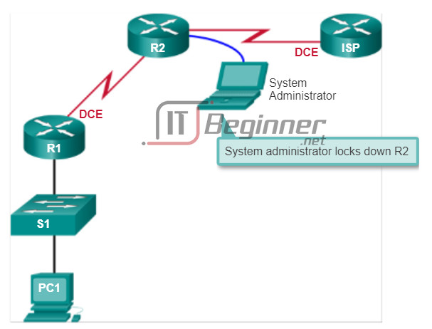
When implementing devices, it is important to follow all security guidelines set by the organization. This includes naming devices in a fashion that allows for easy documentation and tracking, but also maintains some form of security. It is not wise to provide too much information about the use of the device in the hostname. There are many other basic security measures that should be taken.
Additional Password Security
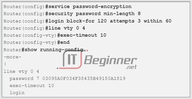
Strong passwords are only as useful as they are secret. There are several steps that can be taken to help ensure that passwords remain secret. Using the global configuration command service password-encryption prevents unauthorized individuals from viewing passwords in plaintext in the configuration file, as shown in the figure. This command causes the encryption of all passwords that are unencrypted.
Additionally, to ensure that all configured passwords are a minimum of a specified length, use the security passwords min-length command in global configuration mode.
Another way hackers learn passwords is simply by brute-force attacks, trying multiple passwords until one works. It is possible to prevent this type of attack by blocking login attempts to the device if a set number of failures occur within a specific amount of time.
Router(config)# login block-for 120 attempts 3 within 60
This command will block login attempts for 120 seconds, if there are three failed login attempts within 60 seconds.
Banners
A banner message is similar to a no trespassing sign. They are important in order to be able to prosecute, in a court of law, anyone that accesses the system inappropriately. Be sure banner messages comply with security policies for the organization.
Router(config)# banner motd #message#
Exec Timeout
Another recommendation is setting executive timeouts. By setting the exec timeout, you are telling the Cisco device to automatically disconnect users on a line after they have been idle for the duration of the exec timeout value. Exec timeouts can be configured on console, vty, and aux ports.
Router(config)# line vty 0 4
Router(config-vty)# exec-timeout 10
This command will disconnect users after 10 minutes.
11.2.4.4 Enable SSH
Remote access via SSH
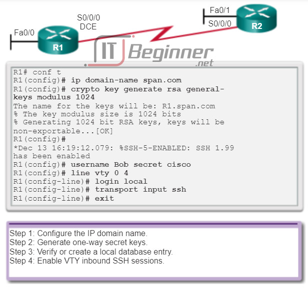
The legacy protocol to manage devices remotely is Telnet. Telnet is not secure. Data contained within a Telnet packet is transmitted unencrypted. Using a tool like Wireshark, it is possible for someone to “sniff” a Telnet session and obtain password information. For this reason, it is highly recommended to enable SSH on devices for secure remote access. It is possible to configure a Cisco device to support SSH using four steps, as shown in the figure.
Step 1. Ensure that the router has a unique host name, and then configure the IP domain name of the network using the ip domain-name domain-name command in global configuration mode.
Step 2. One-way secret keys must be generated for a router to encrypt SSH traffic. The key is what is actually used to encrypt and decrypt data. To create an encryption key, use the crypto key generate rsa general-keys modulus modulus-size command in global configuration mode. The specific meaning of the various parts of this command are complex and out of scope for this course, but for now, just note that the modulus determines the size of the key and can be configured from 360 bits to 2048 bits. The larger the modulus, the more secure the key, but the longer it takes to encrypt and decrypt information. The minimum recommended modulus length is 1024 bits.
Router(config)# crypto key generate rsa general-keys modulus 1024
Step 3. Create a local database username entry using the username name secret secret global configuration command.
Step 4. Enable vty inbound SSH sessions using the line vty commands login local and transport input ssh.
The router SSH service can now be accessed using an SSH client software.
11.2.4.5 Lab – Accessing Network Devices with SSH
In this lab, you will complete the following objectives:
- Part 1: Configure Basic Device Settings
- Part 2: Configure the Router for SSH Access
- Part 3: Examine a Telnet Session with Wireshark
- Part 4: Examine a SSH Session with Wireshark
- Part 5: Configure the Switch for SSH Access
- Part 6: SSH from the CLI on the Switch
Lab – Accessing Network Devices with SSH ./.
11.2.4.6 Lab – Securing Network Devices
In this lab, you will complete the following objectives:
- Part 1: Configure Basic Device Settings
- Part 2: Configure Basic Security Measures on the Router
- Part 3: Configure Basic Security Measures on the Switch
Lab – Securing Network Devices ./.
11.3 Basic Network Performance
11.3.1 Ping
11.3.1.1 Interpreting Ping Results
After the network has been implemented, a network administrator must be able to test the network connectivity to ensure that it is operating appropriately. Additionally, it is a good idea for the network administrator to document the network
The Ping Command
Using the ping command is an effective way to test connectivity. The test is often referred to as testing the protocol stack, because the ping command moves from Layer 3 of the OSI model to Layer 2 and then Layer 1. Ping uses the ICMP protocol to check for connectivity.
The ping command will not always pinpoint the nature of a problem, but it can help to identify the source of the problem, an important first step in troubleshooting a network failure.
The ping command provides a method for checking the protocol stack and IPv4 address configuration on a host as well as testing connectivity to local or remote destination hosts, as shown in the figure. There are additional tools that can provide more information than ping, such as Telnet or Trace, which will be discussed in more detail later.
IOS Ping Indicators
A ping issued from the IOS will yield one of several indications for each ICMP echo that was sent. The most common indicators are:
- ! – indicates receipt of an ICMP echo reply message
- . – indicates a time expired while waiting for an ICMP echo reply message
- U – an ICMP unreachable message was received
The “!” (exclamation mark) indicates that the ping completed successfully and verifies Layer 3 connectivity.
The “.” (period) can indicate problems in the communication. It may indicate that a connectivity problem occurred somewhere along the path. It may also indicate that a router along the path did not have a route to the destination and did not send an ICMP destination unreachable message. It also may indicate that ping was blocked by device security.
The “U” indicates that a router along the path did not have a route to the destination address or that the ping request was blocked and responded with an ICMP unreachable message.
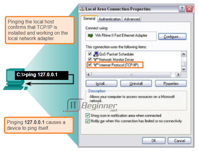
Testing the Loopback
The ping command is used to verify the internal IP configuration on the local host. Recall that this test is accomplished by using the ping command on a reserved address called the loopback (127.0.0.1). This verifies the proper operation of the protocol stack from the network layer to the physical layer – and back – without actually putting a signal on the media.
Ping commands are entered at a command line.
Enter the ping loopback command with this syntax:
C:\> ping 127.0.0.1
The reply from this command would look something like this:
Reply from 127.0.0.1: bytes=32 time<1ms TTL=128
Reply from 127.0.0.1: bytes=32 time<1ms TTL=128
Reply from 127.0.0.1: bytes=32 time<1ms TTL=128
Reply from 127.0.0.1: bytes=32 time<1ms TTL=128
Ping statistics for 127.0.0.1:
Packets: Sent = 4, Received = 4, Lost = 0 (0% loss),
Approximate round trip times in milli-seconds:
Minimum = 0ms, Maximum = 0ms, Average = 0ms
The result indicates that four 32 byte test packets were sent and were returned from host 127.0.0.1 in a time of less than 1 ms. TTL stands for Time-to-Live and defines the number of hops that the ping packet has remaining before it will be dropped.
11.3.1.2 Extended Ping
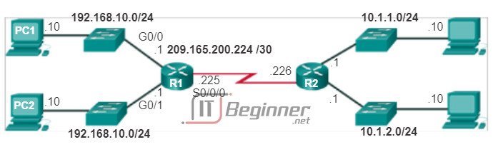
The Cisco IOS offers an “extended” mode of the ping command. This mode is entered by typing ping in privileged EXEC mode, without a destination IP address. A series of prompts are then presented as shown in the example below. Pressing Enter accepts the indicated default values. The example below illustrates how to force the source address for a ping to be 10.1.1.1 (see R2 in the figure); the source address for a standard ping would be 209.165.200.226. By doing this, the network administrator can verify remotely (from R2) that R1 has the route 10.1.1.0/24 in its routing table.
R2# ping
Protocol [ip]:
Target IP address: 192.168.10.1
Repeat count [5]:
Datagram size [100]:
Timeout in seconds [2]:
Extended commands [n]: y
Source address or interface: 10.1.1.1
Type of service [0]:
Set DF bit in IP header? [no]:
Validate reply data? [no]:
Data pattern [0xABCD]:
Loose, Strict, Record, Timestamp, Verbose[none]:
Sweep range of sizes [n]:
Type escape sequence to abort.
Sending 5, 100-byte ICMP Echos to 192.168.10.1, timeout is 2 seconds:
!!!!!
Success rate is 100 percent (5/5), round-trip min/avg/max = 36/97/132 ms
Entering a longer timeout period than the default allows for possible latency issues to be detected. If the ping test is successful with a longer value, a connection exists between the hosts, but latency may be an issue on the network.
Note that entering “y” to the “Extended commands” prompt provides more options that are useful in troubleshooting.
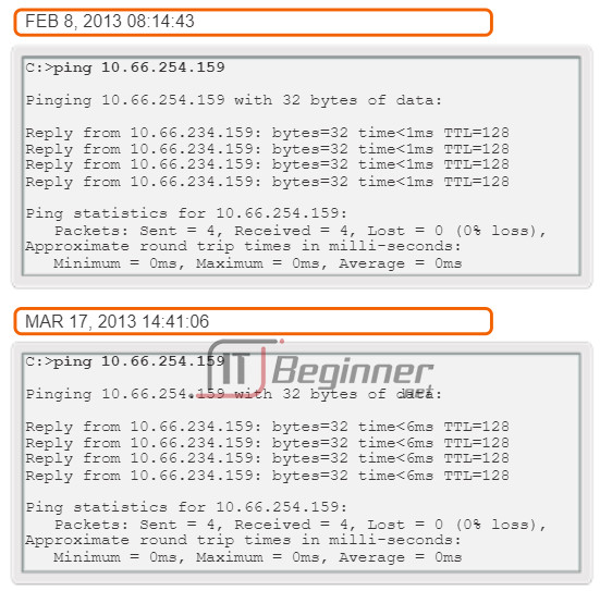
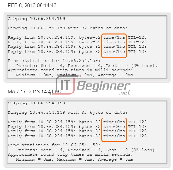
11.3.1.3 Network Baseline
One of the most effective tools for monitoring and troubleshooting network performance is to establish a network baseline. A baseline is a process for studying the network at regular intervals to ensure that the network is working as designed. A network baseline is more than a single report detailing the health of the network at a certain point in time. Creating an effective network performance baseline is accomplished over a period of time. Measuring performance at varying times (Figures 1 and 2) and loads will assist in creating a better picture of overall network performance.
The output derived from network commands can contribute data to the network baseline.
One method for starting a baseline is to copy and paste the results from an executed ping, trace, or other relevant command into a text file. These text files can be time stamped with the date and saved into an archive for later retrieval.
An effective use of the stored information is to compare the results over time (Figure 3). Among items to consider are error messages and the response times from host to host. If there is a considerable increase in response times, there may be a latency issue to address.
The importance of creating documentation cannot be emphasized enough. Verification of host-to-host connectivity, latency issues, and resolutions of identified problems can assist a network administrator in keeping a network running as efficiently as possible.
Corporate networks should have extensive baselines; more extensive than we can describe in this course. Professional-grade software tools are available for storing and maintaining baseline information. In this course, we only cover some basic techniques and discuss the purpose of baselines.
Best practices for baseline processes can be found here.
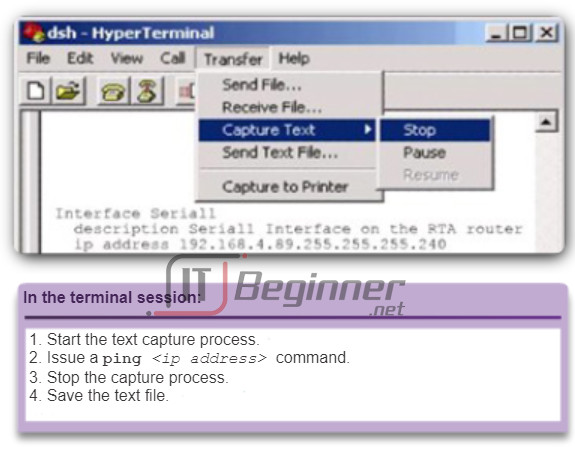
Capturing ping command output can also be completed from the IOS prompt, as shown in Figure 4.
[tabs type=”horizontal”]
[tabs_head]
[tab_title]Figure 1[/tab_title]
[tab_title]Figure 2[/tab_title]
[tab_title]Figure 3[/tab_title]
[tab_title]Figure 4[/tab_title]
[/tabs_head]
[tab]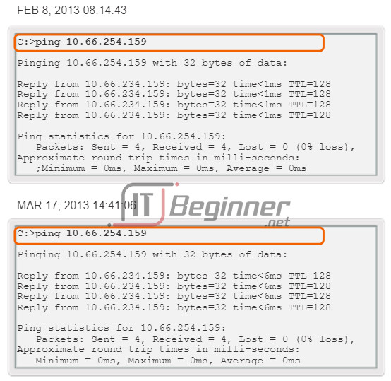 [/tab]
[tab]
[/tab]
[tab]
[/tab]
[tab]
[/tab]
[/tabs]
11.3.2 Tracert
11.3.2.1 Interpreting Tracert Messages
A trace returns a list of hops as a packet is routed through a network. The form of the command depends on where the command is issued. When performing the trace from a Windows computer, use tracert. When performing the trace from a router CLI, use traceroute, as shown in Figure 1.
Like ping commands, trace commands are entered in the command line and take an IP address as the argument.
Assuming that the command will be issued from a Windows computer, we use the tracert form:
C:\> tracert 10.1.0.2
Tracing route to 10.1.0.2 over a maximum of 30 hops
1 2 ms 2 ms 2 ms 10.0.0.254
2 * * * Request timed out.
3 * * * Request timed out.
4 ^C
The only successful response was from the gateway on Router A. Trace requests to the next hop timed out, meaning that the next hop router did not respond. The trace results indicate that the failure is therefore in the internetwork beyond the LAN.
Capturing the traceroute output can also be done from the router prompt, as shown in Figure 2.
[tabs type=”horizontal”]
[tabs_head]
[tab_title]Testing the Path to a Remote Host[/tab_title]
[tab_title]Router Traceroute Capture – Saving to a text file[/tab_title]
[/tabs_head]
[tab]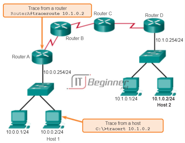 [/tab]
[tab]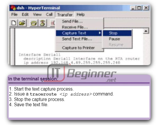 [/tab]
[/tabs]
11.3.2.2 Packet Tracer – Test Connectivity with Traceroute
This activity is designed to help you troubleshoot network connectivity issues using commands to trace the route from source to destination. You are required to examine the output of tracert (the Windows command) and traceroute (the IOS command) as packets traverse the network and determine the cause of a network issue. After the issue is corrected, use the tracert and traceroute commands to verify the completion.
Packet Tracer – Test Connectivity with Traceroute Instructions ./.
Packet Tracer – Test Connectivity with Traceroute – PKA ./.
11.3.2.3 Lab – Testing Network Latency with Ping and Traceroute
In this lab, you will complete the following objectives:
- Part 1: Use Ping to Document Network Latency
- Part 2: Use Traceroute to Document Network Latency
Lab – Testing Network Latency with Ping and Traceroute ./.
11.3.3 Show Commands
11.3.3.1 Common show Commands Revisited
The Cisco IOS CLI show commands display relevant information about the configuration and operation of the device.
Network technicians use show commands extensively for viewing configuration files, checking the status of device interfaces and processes, and verifying the device operational status. The show commands are available whether the device was configured using the CLI or Cisco Configuration Professional.
The status of nearly every process or function of the router can be displayed using a show command. Some of the more popular show commands are:
- show running-config (Figure 1)
- show interfaces (Figure 2)
- show arp (Figure 3)
- show ip route (Figure 4)
- show protocols (Figure 5)
- show version (Figure 6)
Click the buttons in the figure to see more information about the show commands.
[tabs type=”horizontal”]
[tabs_head]
[tab_title]Figure 1[/tab_title]
[tab_title]Figure 2[/tab_title]
[tab_title]Figure 3[/tab_title]
[tab_title]Figure 4[/tab_title]
[tab_title]Figure 5[/tab_title]
[tab_title]Figure 6[/tab_title]
[/tabs_head]
[tab]
R1#show running-config
<Output omitted>
Building configuration...
Current configuration : 1063 bytes
!
version 12.4
service timestamps debug datetime msec
service timestamps log datetime msec
no service password-encryption
hostname R1
enable secret 5 $1$i6w9$dvdpVM6zV10E6tSyLdkR5/
no ip domain lookup
!
interface FastEthernet0/0
 description LAN 192.168.1.0 default gateway
 ip address 192.168.1.1 255.255.255.0
 duplex auto
 speed auto
!
interface FastEthernet0/1
 no ip address
 shutdown
 duplex auto
 speed auto
!
interface Serial0/0/0
 description WAN link to R2
 ip address 192.168.2.1 255.255.255.0
 encapsulation ppp
 clock rate 64000
 no fair-queue
!
interface Serial0/0/1
 no ip address
 shutdown
!
interface Vlan1
 no ip address
!
router rip
 version 2
 network 192.168.1.0
 network 192.168.2.0
!
banner motd ^CUnauthorized Access Prohibited^C
!
ip http server
!
line con 0
 password cisco
 login
line aux 0
line vty 0 4
 password cisco
 login
[/tab]
[tab]
R1#show interfaces
<Output omitted>
FastEthernet0/0 is up, line protocol is up
  Hardware is Gt96k FE, address is 001b.5325.256e
  (bia 001b.5325.256e)
  Internet address is 192.168.1.1/24
  MTU 1500 bytes, BW 100000 Kbit, DLY 100 usec,
    reliability 255/255, txload 1/255, rxload 1/255
  Encapsulation ARPA, loopback not set
  Keepalive set (10 sec)
  Full-duplex, 100Mb/s, 100BaseTX/FX
  ARP type: ARPA, ARP Timeout 04:00:00
  Last input 00:00:17, output 00:00:01, output hang never
  Last clearing of "show interface" counters never
  Input queue: 0/75/0/0 (size/max/drops/flushes);
  Total output drops: 0
  Queueing strategy: fifo
  Output queue: 0/40 (size/max)
  5 minute input rate 0 bits/sec, 0 packets/sec
  5 minute output rate 0 bits/sec, 0 packets/sec
    196 packets input, 31850 bytes
    Received 181 broadcasts, 0 runts, 0 giants, 0 throttles
    0 input errors, 0 CRC, 0 frame, 0 overrun, 0 ignored
    0 watchdog
    0 input packets with dribble condition detected
    392 packets output, 35239 bytes, 0 underruns
    0 output errors, 0 collisions, 3 interface resets
    0 babbles, 0 late collision, 0 deferred
    0 lost carrier, 0 no carrier
    0 output buffer failures, 0 output buffers swapped out

FastEthernet0/1 is administratively down,
line protocol is down

Serial0/0/0 is up, line protocol is up
  Hardware is GT96K Serial
  Internet address is 192.168.2.1/24
  MTU 1500 bytes, BW 1544 Kbit, DLY 20000 usec,
    reliability 255/255, txload 1/255, rxload 1/255
  Encapsulation PPP, LCP Listen, loopback not set
  Keepalive set (10 sec)
  Last input 00:00:02, output 00:00:03, output hang never
  Last clearing of "show interface" counters 00:51:52
  Input queue: 0/75/0/0 (size/max/drops/flushes);
  Total output drops: 0
  Queueing strategy: fifo
  Output queue: 0/40 (size/max)
  5 minute input rate 0 bits/sec, 0 packets/sec
  5 minute output rate 0 bits/sec, 0 packets/sec
    401 packets input, 27437 bytes, 0 no buffer
    Received 293 broadcasts, 0 runts, 0 giants, 0 throttles
    0 input errors, 0 CRC, 0 frame, 0 overrun, 0 ignored, 0 abort
    389 packets output, 26940 bytes, 0 underruns
    0 output errors, 0 collisions, 2 interface resets
    0 output buffer failures, 0 output buffers swapped out
    6 carrier transitions
    DCD=up DSR=up DTR=up RTS=up CTS=up

Serial0/0/1 is administratively down, line protocol is down
[/tab]
[tab]
R1#show arp
Protocol	Address	Age (min) 	Hardware Addr	Type	Interface
Internet	172.17.0.1	- 	001b.5325.256e	ARPA
FastEthernet0/0
Internet	172.17.0.2	12 	000b.db04.a5cd	ARPA
FastEthernet0/0
[/tab]
[tab]
R1#show ip route
Codes:	C - connected, S - static, R - RIP, M - mobile, B - BGP
 	D - EIGRP, EX - EIGRP external, O - OSPF, IA - OSPF inter area
 	N1 - OSPF NSSA external type 1, N2 - OSPF NSSA external type 2
 	E1 - OSPF external type 1, E2 - OSPF external type 2
 	i - IS-IS, su - IS-IS summary, L1 - IS-IS level-1, L2 - IS-IS level-2
 	ia - IS-IS inter area, * - candidate default, U - per-user static route
 	o - ODR, P - periodic downloaded static route

Gateway of last resort is not set
C	192.168.1.0/24 is directly connected, FastEthernet0/0
C	192.168.2.0/24 is directly connected, Serial0/0/0
R	192.168.3.0/24 [120/1] via 192.168.2.2, 00:00:24, Serial0/0/0
[/tab]
[tab]
R1#show protocols
Global values:
  Internet Protocol routing is enabled
FastEthernet0/0 is up, line protocol is up
  Internet address is 192.168.1.1/24
FastEthernet0/1 is administratively down, line protocol is down
FastEthernet0/1/0 is up, line protocol is down
FastEthernet0/1/1 is up, line protocol is down
FastEthernet0/1/2 is up, line protocol is down
FastEthernet0/1/3 is up, line protocol is down
Serial0/0/0 is up, line protocol is up
  Internet address is 192.168.2.1/24
Serial0/0/1 is administratively down, line protocol is down
Vlan1 is up, line protocol is down
[/tab]
[tab]
R1#show version
<Output omitted>
Cisco IOS Software, 1841 Software (C1841-ADVIPSERVICESK9-M),
Version 12.4(10b),
RELEASE SOFTWARE (fc3)
Technical Support: http://www.cisco.com/techsupport
Copyright (c) 1986-2007 by Cisco Systems, Inc.
Compiled Fri 19-Jan-07 15:15 by prod_rel_team

ROM: System Bootstrap, Version 12.4(13r)T, RELEASE SOFTWARE (fc1)
R1 uptime is 43 minutes
System returned to ROM by reload at 22:05:12 UTC Sat Jan 5 2008
System image file is "flash:c1841-advipservicesk9-mz.124-10b.bin"

Cisco 1841 (revision 6.0) with 174080K/22528K bytes of memory.
Processor board ID FTX1111W0QF
6 FastEthernet interfaces
2 Serial(sync/async) interfaces
1 Virtual Private Network (VPN) Module
DRAM configuration is 64 bits wide with parity disabled.
191K bytes of NVRAM.
62720K bytes of ATA CompactFlash (Read/Write)

Configuration register is 0x2102
[/tab]
[/tabs]
11.3.3.2 Viewing Router Settings with the show version Command
After the startup configuration file is loaded and the router boots successfully, the show version command can be used to verify and troubleshoot some of the basic hardware and software components used during the bootup process. The output from the show version command includes:
- The Cisco IOS software version being used.
- The version of the system bootstrap software, stored in ROM memory that was initially used to boot the router.
- The complete filename of the Cisco IOS image and where the bootstrap program located it.
- Type of CPU on the router and amount of RAM. It may be necessary to upgrade the amount of RAM when upgrading the Cisco IOS software.
- The number and type of physical interfaces on the router.
- The amount of NVRAM. NVRAM is used to store the startup-config file.
- The amount of flash memory on the router. It may be necessary to upgrade the amount of flash when upgrading the Cisco IOS software.
- The currently configured value of the software configuration register in hexadecimal.
Click Play in the figure to see an animation about identification of these features of the show version output.
The configuration register tells the router how to boot up. For example, the factory default setting for the configuration register is 0x2102. This value indicates that the router attempts to load a Cisco IOS software image from flash and loads the startup configuration file from NVRAM. It is possible to change the configuration register and, therefore, change where the router looks for the Cisco IOS image and the startup configuration file during the bootup process. If there is a second value in parentheses, it denotes the configuration register value to be used during the next reload of the router.
Click the Note icon at the bottom right corner of the figure to obtain more information about the configuration register.
11.3.3.3 Viewing Switch Settings with the show version Command
The show version command on a switch displays information about the currently loaded software version, along with hardware and device information. Some of the information displayed by this command is:
- Software version – IOS software version
- Bootstrap version – Bootstrap version
- System up-time – Time since last reboot
- System restart info – Method of restart (e.g., power cycle, crash)
- Software image name – IOS filename
- Switch platform and processor type – Model number and processor type
- Memory type (shared/main) – Main processor RAM and shared packet I/O buffering
- Hardware interfaces – Interfaces available on the switch
- Configuration register – Sets bootup specifications, console speed setting, and related parameters.
The figure shows a sample of typical show version output displayed by a switch.
Switch#show version
Cisco IOS Software, C2960 Software (C2960-LANBASE-M), Version 12.2(25)SEE2, RELEASE SOFTWARE (fc1)
Copyright (c) 1986-2006 by Cisco Systems, Inc.
Compiled Fri 28-Jul-06 04:33 by yenanh
Image text-base: 0x00003000, data-base: 0x00AA2F34

ROM: Bootstrap program is C2960 boot loader
BOOTLDR: C2960 Boot Loader (C2960-HBOOT-M) Version 12.2(25r)SEE1, RELEASE SOFTWARE (fc1)
Switch uptime is 2 minutes
System returned to ROM by power-on
System image file is "flash:c2960-lanbase-mz.122-25.SEE2/c2960-lanbase-mz.122-25.SEE2.bin"

cisco WS-C2960-24TT-L (PowerPC405) processor (revision B0) with 61440K/4088K bytes of memory.
Processor board ID FOC1107Z9ZN
Last reset from power-on
1 Virtual Ethernet interface
24 FastEthernet interfaces
2 Gigabit Ethernet interfaces
The password-recovery mechanism is enabled.

64K bytes of flash-simulated non-volatile configuration memory.
Base ethernet MAC Address	: 00:1B:53:03:17:00
Motherboard assembly number	: 73-10390-03
Power supply part number	: 341-0097-02
Motherboard serial number	: FOC11071TTJ
Power supply serial number	: AZS110605RU
Model revision number	: B0
Motherboard revision number	: C0
Model number	: WS-C2960-24TT-L
System serial number	: FOC1107Z9ZN
Top Assembly Part Number	: 800-27221-02
Top Assembly Revision Number	: C0
Version ID	: V02
CLEI Code Number	: COM3L00BRA
Hardware Board Revision Number	: 0x01

Switch	Ports	Model	SW Version	SW Image
------	-----	-----	----------	----------
*    1	26	WS-C2960-24TT-L	12.2(25)SEE2	C2960-LANBASE-M

Configuration register is 0xF

Switch#
11.3.3.4 Packet Tracer – Using show Commands
This activity is designed to reinforce the use of router show commands. You are not required to configure, but rather examine the output of several show commands.
Packet Tracer – Using Show Commands Instructions ./.
Packet Tracer – Using Show Commands – PKA ./.
11.3.4 Host and IOS Commands
11.3.4.1 ipconfig Command Options
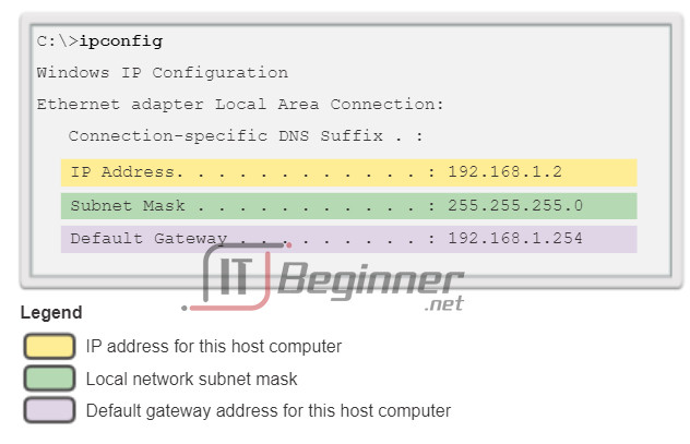
As shown in Figure 1, the IP address of the default gateway of a host can be viewed by issuing the ipconfig command at the command line of a Windows computer.
A tool to examine the MAC address of our computer is ipconfig /all. Note that in Figure 2, the MAC address of the computer is now displayed along with a number of details regarding the Layer 3 addressing of the device. Try using this command.
In addition, the manufacturer of the network interface in the computer can be identified through the OUI portion of the MAC address. This can be researched on the Internet.
The DNS Client service on Windows PCs optimizes the performance of DNS name resolution by storing previously resolved names in memory, as well. The ipconfig /displaydns command displays all of the cached DNS entries on a Windows computer system.
[tabs type=”horizontal”]
[tabs_head]
[tab_title]ipconfig[/tab_title]
[tab_title]ipconfig /all[/tab_title]
[/tabs_head]
[tab]
[/tab]
[tab]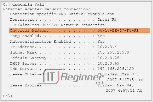 [/tab]
[/tabs]
11.3.4.2 arp Command Options
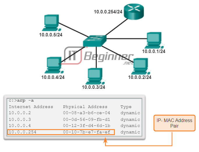
The arp command enables the creation, editing, and display of mappings of physical addresses to known IPv4 addresses. The arp command is executed from the Windows command prompt.
To execute an arp command, at the command prompt of a host, enter:
C:\host1> arp -a
As shown in the figure the arp –a command lists all devices currently in the ARP cache of the host, which includes the IPv4 address, physical address, and the type of addressing (static/dynamic), for each device.
The cache can be cleared by using the arp -d command in the event the network administrator wants to repopulate the cache with updated information.
Note: The ARP cache only contains information from devices that have been recently accessed. To ensure that the ARP cache is populated, ping a device so that it will have an entry in the ARP table.
11.3.4.3 show cdp neighbors Command Options
Examine the output from the show cdp neighbors commands in Figure 1, with the topology in Figure 2. Notice that R3 has gathered some detailed information about R2 and the switch connected to the Fast Ethernet interface on R3.
CDP is a Cisco-proprietary protocol that runs at the data link layer. Because CDP operates at the data link layer, two or more Cisco network devices, such as routers that support different network layer protocols, can learn about each other even if Layer 3 connectivity does not exist.
When a Cisco device boots up, CDP starts up by default. CDP automatically discovers neighboring Cisco devices running CDP, regardless of which Layer 3 protocol or suites are running. CDP exchanges hardware and software device information with its directly connected CDP neighbors.
CDP provides the following information about each CDP neighbor device:
- Device identifiers – For example, the configured host name of a switch
- Address list – Up to one network layer address for each protocol supported
- Port identifier – The name of the local and remote port-in the form of an ASCII character string such as ethernet0
- Capabilities list – For example, whether this device is a router or a switch
- Platform – The hardware platform of the device; for example, a Cisco 1841 series router
The show cdp neighbors detail command reveals the IP address of a neighboring device. CDP will reveal the neighbor’s IP address regardless of whether or not you can ping the neighbor. This command is very helpful when two Cisco routers cannot route across their shared data link. The show cdp neighbors detail command will help determine if one of the CDP neighbors has an IP configuration error.
For network discovery situations, knowing the IP address of the CDP neighbor is often all the information needed to Telnet into that device.
For obvious reasons, CDP can be a security risk. Because some IOS versions send out CDP advertisements by default, it is important to know how to disable CDP.
To disable CDP globally, use the global configuration command no cdp run. To disable CDP on an interface, use the interface command no cdp enable.
[tabs type=”horizontal”]
[tabs_head]
[tab_title]Figure 1[/tab_title]
[tab_title]Figure 2[/tab_title]
[/tabs_head]
[tab]
R3#show cdp neighbors

Capability Codes:	R - Router, T - Trans Bridge,
 	B - Source Route Bridge
 	S - Switch, H - Host, I - IGMP,
 	r - Repeater, P - Phone

Device ID	Local Intrfce	Holdtme	Capability	Platform	Port ID
S3	Fas 0/0	151	S I	WS-C2950	Fas 0/6
R2	Ser 0/0/1	125	R	1841	Ser 0/0/1

R3#show cdp neighbors detail
Device ID: R2
Entry address(es):
IP address : 192.168.1.2
Platform: Cisco 1841, Capabilities: Router Switch IGMP
Interface: Serial0/0/1, Port ID (outgoing port): Serial0/0/1
Holdtime : 161 sec

Version :
Cisco IOS Software, 1841 Software (C1841-ADVIPSERVICESK9-M),
Version 12.4(10b), RELEASE SOFTWARE (fc3)
Technical Support: http://www.cisco.com/techsupport
Copyright (c) 1986-2007 by Cisco Systems, Inc.
Compiled Fri 19-Jan-07 15:15 by prod_rel_team

advertisement version: 2
VTP Management Domain: ''

-------------------------------
Device ID: S3
Entry address(es):
Platform: cisco WS-C2950-24, Capabilities: Switch IGMP
Interface: FastEthernet0/0, Port ID (outgoing port): FastEthernet0/11
Holdtime : 148 sec

Version :
Cisco Internetwork Operating System Software
IOS (tm) C2950 Software (C2950-I6Q4L2-M), Version 12.1(9)EA1,
RELEASE SOFTWARE (fc1)
Copyright (c) 1986-2002 by cisco Systems, Inc.
Compiled Wed 24-Apr-02 06:57 by antonino

advertisement version: 2
Protocol Hello: OUI=0x00000C, Protocol ID=0x0112; payload len=27, value=00000000FFFFFFFF0
10231FF000000000000000AB769F6C0FF0000
VTP Management Domain: 'CCNA3'
Duplex: full

R3#
[/tab]
[tab]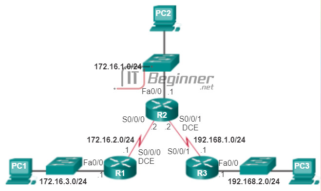 [/tab]
[/tabs]
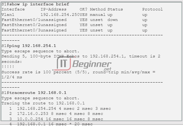
11.3.4.4 Using the show ip interface brief Command
In the same way that commands and utilities are used to verify a host configuration, commands can be used to verify the interfaces of intermediate devices. The Cisco IOS provides commands to verify the operation of router and switch interfaces.
Verifying Router Interfaces
One of the most frequently used commands is the show ip interface brief command. This command provides a more abbreviated output than the show ip interface command. It provides a summary of the key information for all the network interfaces on a router.
Figure 1 shows the topology that is being used in this example.
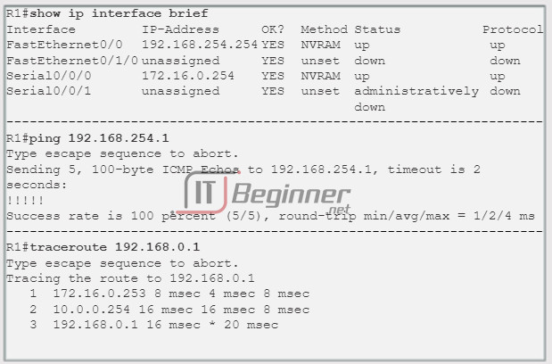
On Figure 2, click the R1 button. The show ip interface brief output displays all interfaces on the router, the IP address assigned to each interface, if any, and the operational status of the interface.
According to the output, the FastEthernet 0/0 interface has an IP address of 192.168.254.254. The last two columns in this line show the Layer 1 and Layer 2 status of this interface. The up in the Status column shows that this interface is operational at Layer 1. The up in the Protocol column indicates that the Layer 2 protocol is operational.
Also notice that the Serial 0/0/1 interface has not been enabled. This is indicated by administratively down in the Status column.
As with any end device, we can verify Layer 3 connectivity with the ping and traceroute commands. In this example, both the ping and trace commands show successful connectivity.
Verifying the Switch Interfaces
On Figure 2, click the S1 button. The show ip interface brief command can also be used to verify the status of the switch interfaces. The IP address for the switch is applied to a VLAN interface. In this case, the Vlan1 interface is assigned an IP address of 192.168.254.250 and has been enabled and is operational.
The output also shows that the FastEthernet0/1 interface is down. This indicates that either, no device is connected to the interface, or that the device that is connected to this interface has a network interface that is not operational.
In contrast, the output shows that the FastEthernet0/2 and FastEthernet0/3 interfaces are operational. This is indicated by both the Status and Protocol being shown as up.
The switch can also test its Layer 3 connectivity with the show ip interface brief and traceroute commands. In this example, both the ping and trace commands show successful connectivity.
It is important to keep in mind that an IP address is not required for a switch to perform its job of frame forwarding at Layer 2. An IP address is only necessary if the switch will be managed over the network using Telnet or SSH. If the network administrator plans to remotely connect to the switch from a location outside of the local LAN, then a default gateway must also be configured.
[tabs type=”horizontal”]
[tabs_head]
[tab_title]Figure 1[/tab_title]
[tab_title]Figure 2[/tab_title]
[/tabs_head]
[tab]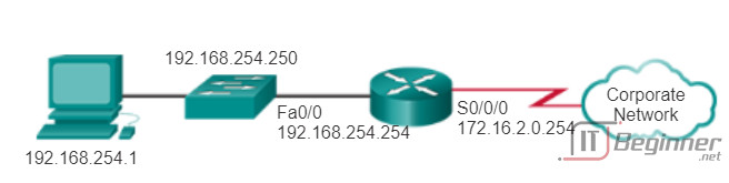 [/tab]
[tab]
[/tab]
[/tabs]
11.3.4.5 Activity – Show Commands
11.3.4.6 Lab – Using the CLI to Gather Network Device Information.pdf
In this lab, you will complete the following objectives:
- Part 1: Set Up Topology and Initialize Devices
- Part 2: Configure Devices and Verify Connectivity
- Part 3: Gather Network Device Information
Lab – Using the CLI to Gather Network Device Information ./.
11.4 Managing IOS Configuration Files
11.4.1 Router and Switch File Systems
11.4.1.1 Router File Systems
In addition to implementing and securing a small network, it is also the job of the network administrator to manage configuration files. Managing the configuration files is important for purposes of backup and retrieval in the event of a device failure.
The Cisco IOS File System (IFS) provides a single interface to all the file systems a router uses, including:
- Flash memory file systems
- Network file systems (TFTP and FTP)
- Any other endpoint for reading or writing data such as NVRAM, the running configuration, ROM, and others
With Cisco IFS, all files can be viewed and classified (image, text file, and so forth), including files on remote servers. For example, it is possible to view a configuration file on a remote server to verify that it is the correct configuration file before loading the file on the router.
Cisco IFS allows the administrator to move around to different directories and list the files in a directory, and to create subdirectories in flash memory or on a disk. The directories available depend on the device.
The Figure 1 displays the output of the show file systems command, which lists all of the available file systems on a Cisco 1941 router, in this example. This command provides useful information such as the amount of available and free memory, the type of file system, and its permissions. Permissions include read only (ro), write only (wo), and read and write (rw), shown in the Flags column of the command output.
Although there are several file systems listed, of interest to us will be the tftp, flash, and nvram file systems.
Notice that the flash file system also has an asterisk preceding it. This indicates that flash is the current default file system. The bootable IOS is located in flash; therefore, the pound symbol (#) is appended to the flash listing indicating that it is a bootable disk.
The Flash File System
Figure 2 lists the content of the current default file system, which in this case is flash as was indicated by the asterisks preceding the listing in the previous figure. There are several files located in flash, but of specific interest is the last listing. This is the name of the current Cisco IOS file image that is running in RAM.
The NVRAM File System
To view the contents of NVRAM, you must change the current default file system using the cd (change directory) command, as shown in Figure 3. The pwd (present working directory) command verifies that we are viewing the NVRAM directory. Finally, the dir (directory) command lists the contents of NVRAM. Although there are several configuration files listed, of specific interest is the startup-configuration file.
[tabs type=”horizontal”]
[tabs_head]
[tab_title]File Systems[/tab_title]
[tab_title]Flash[/tab_title]
[tab_title]NVRAM[/tab_title]
[/tabs_head]
[tab]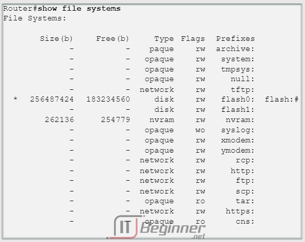 [/tab]
[tab]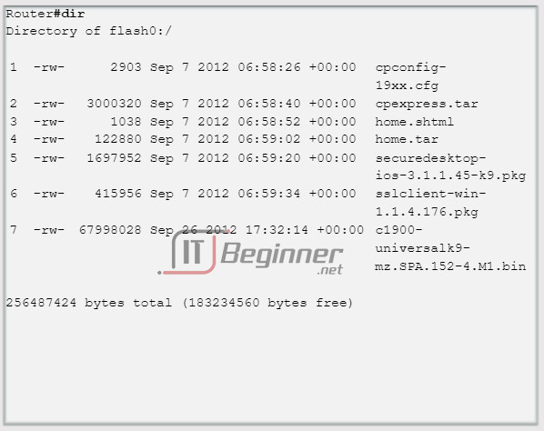 [/tab]
[tab]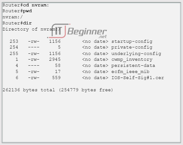 [/tab]
[/tabs]
11.4.1.2 Switch File Systems
With the Cisco 2960 switch flash file system, you can copy configuration files, and archive (upload and download) software images.
The command to view the file systems on a Catalyst switch is the same as on a Cisco router: show file systems, as shown in the figure.
Many basic UNIX commands are supported on Cisco switches and routers: cd for changing to a file system or directory, dir to display directories on a file system, and pwd to display the working directory.
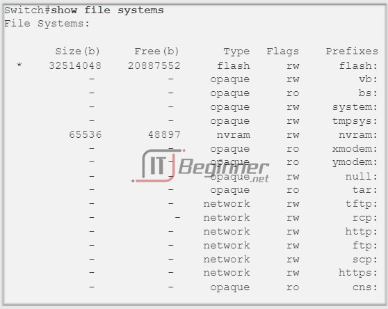
11.4.2 Back up and Restore Configuration files
11.4.2.1 Backing up and Restoring using Text Files
Backup Configurations with Text Capture (Tera Term)
Configuration files can be saved/archived to a text file using Tera Term.
As shown in the figure, the steps are:
Step 1. On the File menu, click Log.
Step 2. Choose the location to save the file. Tera Term will begin capturing text.
Step 3. After capture has been started, execute the show running-config or show startup-config command at the privileged EXEC prompt. Text displayed in the terminal window will be directed into the chosen file.
Step 4. When the capture is complete, select Close in the Tera Term: Log window.
Step 5. View the file to verify that it was not corrupted.
Restoring Text Configurations
A configuration can be copied from a file to a device. When copied from a text file and pasted into a terminal window, the IOS executes each line of the configuration text as a command. This means that the file will require editing to ensure that encrypted passwords are in plain text and that non-command text such as “–More–” and IOS messages are removed. This process is discussed in the lab.
Further, at the CLI, the device must be set at the global configuration mode to receive the commands from the text file being pasted into the terminal window.
When using Tera Term, the steps are:
Step 1. On the File menu, click Send file.
Step 2. Locate the file to be copied into the device and click Open.
Step 3. Tera Term will paste the file into the device.
The text in the file will be applied as commands in the CLI and become the running configuration on the device. This is a convenient method for manually configuring a router.
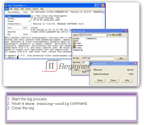
11.4.2.2 Backing up and Restoring using TFTP
Backup Configurations with TFTP
Copies of configuration files should be stored as backup files in the event of a problem. Configuration files can be stored on a Trivial File Transfer Protocol (TFTP) server or a USB drive. A configuration file should also be included in the network documentation.
To save the running configuration or the startup configuration to a TFTP server, use either the copy running-config tftp or copy startup-config tftp command as shown in the figure. Follow these steps to back up the running configuration to a TFTP server:
Step 1. Enter the copy running-config tftp command.
Step 2. Enter the IP address of the host where the configuration file will be stored.
Step 3. Enter the name to assign to the configuration file.
Step 4. Press Enter to confirm each choice.
Restoring Configurations with TFTP
To restore the running configuration or the startup configuration from a TFTP server, use either the copy tftp running-config or copy tftp startup-config command. Use these steps to restore the running configuration from a TFTP server:
Step 1. Enter the copy tftp running-config command.
Step 2. Enter the IP address of the host where the configuration file is stored.
Step 3. Enter the name to assign to the configuration file.
Step 4. Press Enter to confirm each choice.
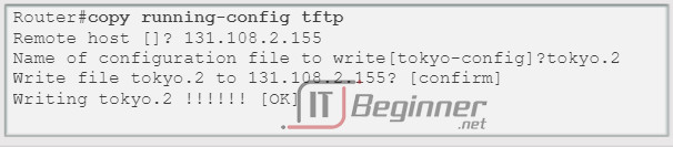
11.4.2.3 Using USB Ports on a Cisco Router
The Universal Serial Bus (USB) storage feature enables certain models of Cisco routers to support USB flash drives. The USB flash feature provides an optional secondary storage capability and an additional boot device. Images, configurations, and other files can be copied to or from the Cisco USB flash memory with the same reliability as storing and retrieving files using the Compact Flash card. In addition, modular integrated services routers can boot any Cisco IOS Software image saved on USB flash memory.
Cisco USB flash modules are available in 64MB, 128 MB, and 256MB versions.
To be compatible with a Cisco router, a USB flash drive must be formatted in a FAT16 format. If that is not the case, the show file systems command will display an error indicating an incompatible file system.
Here is an example of the use of the dir command on a USB file system:
Router# dir usbflash0:
Directory of usbflash0:/
1 -rw- 30125020 Dec 22 2032 05:31:32 +00:00 c3825-entservicesk9-mz.123-14.T
63158272 bytes total (33033216 bytes free)
Ideally, USB flash can hold multiple copies of the Cisco IOS and multiple router configurations. The USB flash allows an administrator to easily move and copy those IOS files and configurations from router to router, and many times, the copying process can take place several times faster than it would over a LAN or WAN. Note that the IOS may not recognize the proper size of the USB flash, but that does not necessarily mean that the flash is unsupported. Additionally, the USB ports on a router are usually USB 2.0, as shown in the figure.
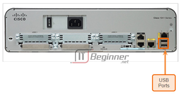
11.4.2.4 Backing up and Restoring using a USB
Backup Configurations with a USB flash drive
When backing up to a USB port, it is a good idea to issue the show file systems command to verify that the USB drive is there and confirm the name, as shown in Figure 1.
Next, use the copy run usbflash0:/ command to copy the configuration file to the USB flash drive. Be sure to use the name of the flash drive, as indicated in the file system. The slash is optional but indicates the root directory of the USB flash drive.
The IOS will prompt for the filename. If the file already exists on the USB flash drive, the router will prompt for overwrite, as seen in Figure 2.
Use the dir command to see the file on the USB drive and use the more command to see the contents, as seen in Figure 3.
Restore Configurations with a USB flash drive
In order to copy the file back, it will be necessary to edit the USB R1-Config file with a text editor to make it a valid config file; otherwise, there are a lot of entries that are invalid commands and no interfaces will be brought up.
R1# copy usbflash0:/R1-Config running-config
Destination filename [running-config]?
[tabs type=”horizontal”]
[tabs_head]
[tab_title]Figure 1[/tab_title]
[tab_title]Figure 2[/tab_title]
[tab_title]Figure 3[/tab_title]
[/tabs_head]
[tab]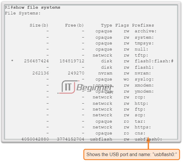 [/tab]
[tab]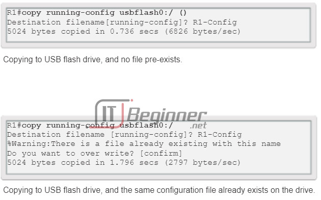 [/tab]
[tab]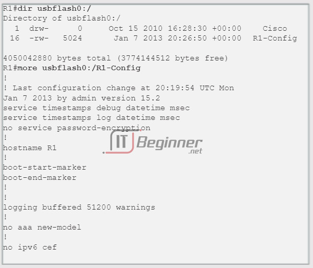 [/tab]
[/tabs]
11.4.2.5 Packet Tracer – Backing up Configuration Files
This activity is designed to show how to restore a configuration from a backup and then perform a new backup. Due to an equipment failure, a new router has been put in place. Fortunately backup configuration files have been saved to a Trivial File Transfer Protocol (TFTP) Server. You are required to restore the files from the TFTP Server to get the router back online with as little down time as possible.
Packet Tracer – Backing Up Configuration Files Instructions ./.
Packet Tracer – Backing Up Configuration Files – PKA ./.
11.4.2.6 Lab – Managing Router Configuration Files with Tera Term
In this lab, you will complete the following objectives:
- Part 1: Configure Basic Device Settings
- Part 2: Use Terminal Emulation Software to Create a Backup Configuration File
- Part 3: Use a Backup Configuration File to Restore a Router
Lab – Managing Router Configuration Files with Terminal Emulation Software ./.
11.4.2.7 Lab – Managing Device Configuration Files Using TFTP, Flash, and USB
In this lab, you will complete the following objectives:
- Part 1: Build the Network and Configure Basic Device Settings
- Part 2: (Optional) Download TFTP Server Software
- Part 3: Use TFTP to Back Up and Restore the Switch Running Configuration
- Part 4: Use TFTP to Back Up and Restore the Router Running Configuration
- Part 5: Back Up and Restore Running Configurations Using Router Flash Memory
- Part 6: (Optional) Use a USB Drive to Back Up and Restore the Running Configuration
Lab – Managing Device Configuration Files Using TFTP, Flash, and USB ./.
11.4.2.8 Lab – Researching Password Recovery Procedures
In this lab, you will complete the following objectives:
- Part 1: Research the Configuration Register
- Part 2: Document the Password Recovery Procedure for a Specific Cisco Router
Lab – Researching Password Recovery Procedures ./.
11.5 Integrated Routing Services
11.5.1 Integrated Router
11.5.1.1 Multi-Function Device
The use of networking is not limited to small businesses and large organizations.
Another environment that is increasingly taking advantage of networking technology is the home. Home networks are being used to provide connectivity and Internet sharing among multiple personal computers systems and laptops throughout the house. They also allow individuals to take advantage of various services such as print sharing to a network printer, centralized storage of photos, music, and movies on a network attached storage (NAS) appliance; as well as allowing other end user devices, such as tablet computers, cell phones, and even home appliances, such as a television, to have access to Internet services.
A home network is very similar to a small-business network. However, most home networks, and many small business networks, do not require high-volume devices, such as dedicated routers and switches. Smaller scale devices, as long as they provide the same functionality of routing and switching, are all that are required. For this reason, many home and small business networks utilize the service of a multi-function device.
For the purpose of this course, multi-function devices will be referred to as integrated routers.
An integrated router is like having several different devices connected together. For example, the connection between the switch and the router still occurs, but it occurs internally. When a packet is forwarded from one device to another on the same local network, the integrated switch will automatically forward the packet to the destination device. If a packet is forwarded to a device on a remote network, however, the integrated switch will then forward the packet to the internal router connection. The internal router will then determine the best path and forward the packet out accordingly.
Most integrated routers offer both wired switching capabilities and wireless connectivity, and serve as the access point (AP) in the wireless network, as shown in Figure 1. Wireless connectivity is a popular, flexible, and cost-effective way for homes, and businesses alike, to provide network services to end devices.
Figures 2 and 3 list some common advantages and considerations for using wireless.
In addition to supporting routing, switching and wireless connectivity, many additional features may be available on an integrated router, including: DHCP service, a firewall, and even network attached storage services.
[tabs type=”horizontal”]
[tabs_head]
[tab_title]Figures 1[/tab_title]
[tab_title]Figures 2[/tab_title]
[tab_title]Figures 3[/tab_title]
[/tabs_head]
[tab] [/tab]
[tab]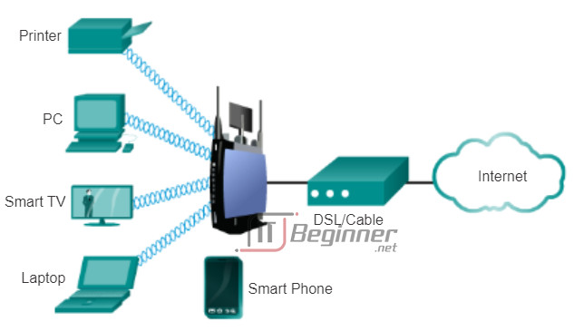
Benefits of Wireless LAN Technology
- Mobility – allows for easy connection of both stationary and mobile clients
- Scalability – can be easily expanded to allow more users to connect and to increase the coverage area
- Flexibility – provides anytime, anywhere connectivity
- Cost Savings – equipment costs continue to fall as the technology matures
- Reduced installation time – installation of a single piece of equipment can provide connectivity for a large number of people
- Reliability in harsh environments – easy to install in emergency and hostile environments
[/tab]
[tab]
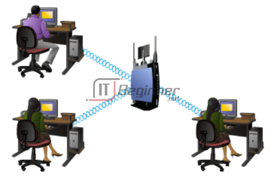
Limitations of Wireless LAN Technology
- Interference – Wireless technology is susceptible to interference from other devices that produce electromagnetic energies. This includes: cordless phones, microwaves, televisions, and other wireless LAN implementations.
- Network and Data security – Wireless LAN technology is designed to provide access to the data being transmitted, not security of the data. Additionally, it can provide an unprotected entrance into the wired network.
- Technology – Wireless LAN technology continues to evolve. Wireless LAN technology does not currently provide the speed or reliability of wired LANs.
[/tab]
[/tabs]
11.5.1.2 Types of Integrated Routers
Integrated routers can range from small devices designed for home office and small business applications to more powerful devices that can support enterprise branch offices.
An example of this type of integrated router is a Linksys wireless router, as shown in the figure. This type of integrated router is simple in design and does not typically have separate components. This reduces the cost of the device. However, in the event of a failure, it is not possible to replace any single failed component. As such, they create a single point of failure, and are not optimized for any one function.
Another example of an integrated router is the Cisco integrated services router or ISR. The Cisco ISR product family offers a wide range of products, including those designed for small office and home office environments as well as those designed for larger networks. Many of the ISRs offer modularity and have separate components for each function, such as a switch component and a router component. This enables individual components to be added, replaced, and upgraded as necessary.
All integrated routers allow for basic configuration settings such as passwords, IP addresses, and DHCP settings, which are the same whether the device is being used to connect wired or wireless hosts. However, if using the wireless functionality, additional configuration parameters are required, such as setting the wireless mode, SSID, and the wireless channel.
[tabs type=”horizontal”]
[tabs_head]
[tab_title]Front[/tab_title]
[tab_title]Rear[/tab_title]
[/tabs_head]
[tab]
LED Descriptions
- Power LED – indicates the presence of power to the device; Solid green LED
- WLAN LED – indicates status of wireless connections
- 1 – 4 LEDs – indicates status of the wired Ethernet connections
- Internet LED – indicates status of the Internet connection
Color Status of LEDs:
- Green – indicates a connection is made with an end device
- Red or yellow – usually indicates a problem with the connection
- Blinking – indicates activity on the port
[/tab]
[tab]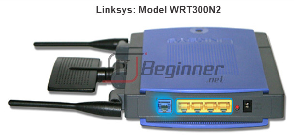
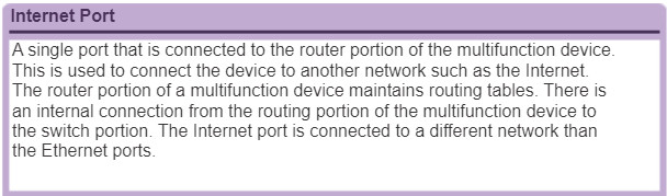
[/tab]
[/tabs]
11.5.1.3 Wireless Capability
Wireless Mode
The wireless mode refers to setting the IEEE 802.11 wireless standard that the network will use. There are four amendments to the IEEE 802.11 standard that describe different characteristics for wireless communications; they are 802.11a, 802.11b, 802.11g, and 802.11n. Figure 1 lists more information about each standard.
Most integrated wireless routers support 802.11b, 802.11g, and 802.11n. The three technologies are compatible, but all devices on the network must operate at the same standard common to all devices. For example: If an 802.11n router is connected to a laptop with 802.11n, the network would function as an 802.11n standard. However, add an 802.11b wireless printer to the network. Both the router and the laptop will revert to using the slower 802.11b standard for all communications. Therefore, keeping older wireless devices on the network will make the entire network slow down. It is important to keep that in mind when deciding whether or not to keep older wireless devices.
Service Set Identifier (SSID)
There may be many other wireless networks in your area. It is important that the wireless devices connect to the correct WLAN. This is done using a Service Set Identifier (SSID).
The SSID is a case-sensitive, alpha-numeric name for your home wireless network. The name can be up to 32-characters in length. The SSID is used to tell wireless devices which WLAN they belong to and with which other devices they can communicate. Regardless of the type of WLAN installation, all wireless devices in a WLAN must be configured with the same SSID in order to communicate.
Wireless Channel
Channels are created by dividing up the available RF spectrum. Each channel is capable of carrying a different conversation. This is similar to the way that multiple television channels are transmitted across a single medium. Multiple APs can function in close proximity to one another as long as they use different channels for communication.
11.5.1.4 Basic Security of Wireless
Security measures should also be planned and configured before connecting the AP to the network or ISP.
As shown in Figure 1, some of the more basic security measures include:
- Change default values for the SSID, usernames, and passwords
- Disable broadcast SSID
- Configure encryption using WEP or WPA
Encryption is the process of transforming data so that even if it is intercepted it is unusable.
Wired Equivalency Protocol (WEP)
WEP is an advanced security feature that encrypts network traffic as it travels through the air. WEP uses pre-configured keys to encrypt and decrypt data, as shown in Figure 2.
A WEP key is entered as a string of numbers and letters and is generally 64 bits or 128 bits long. In some cases, WEP supports 256 bit keys as well. To simplify creating and entering these keys, many devices include a Passphrase option. The passphrase is an easy way to remember the word or phrase used to automatically generate a key.
In order for WEP to function, the AP, as well as every wireless device allowed to access the network must have the same WEP key entered. Without this key, devices will not be able to understand the wireless transmissions.
There are weaknesses within WEP, including the use of a static key on all WEP enabled devices. There are applications available to attackers that can be used to discover the WEP key. These applications are readily available on the Internet. Once the attacker has extracted the key, they have complete access to all transmitted information.
One way to overcome this vulnerability is to change the key frequently. Another way is to use a more advanced and secure form of encryption known as Wi-Fi Protected Access (WPA).
Wi-Fi Protected Access (WPA)
WPA also uses encryption keys from 64 bits up to 256 bits. However, WPA, unlike WEP, generates new, dynamic keys each time a client establishes a connection with the AP. For this reason, WPA is considered more secure than WEP because it is significantly more difficult to crack.
There are several other security implementations that can be configured on a wireless AP, including MAC address filtering, authentication, and traffic filtering. However, those security implementations are beyond the scope of this course.
[tabs type=”horizontal”]
[tabs_head]
[tab_title]Figure 1[/tab_title]
[tab_title]Figure 2[/tab_title]
[/tabs_head]
[tab]
Basic Security
- Change default values
- Disable SSID broadcasting
- Enable encryption
[/tab]
[tab] [/tab]
[/tabs]
11.5.2 Configuring the Integrated Router
11.5.2.1 Configuring the Integrated Router
A Linksys wireless router is a common device used in home and small business networks, and will be used in this course to demonstrate basic configurations of an integrated router. A typical Linksys device offers five to eight Ethernet ports for wired connectivity, in addition to acting as a wireless access point. The Linksys device also acts as both a DHCP server and a mini-webserver that supports a web based graphical user interface (GUI).
Accessing and Configuring a Linksys Router
Initially access the router by cabling a computer to one of the router’s LAN Ethernet ports, as shown in the figure. Once cabled, the connecting device will automatically obtain IP addressing information, including a default gateway address, from the integrated router. The default gateway address is the IP address of the Linksys device. Check the computer network settings using the ipconfig /all command to obtain this address. You can now type that IP address into a web browser on the computer to access the web-based configuration GUI.
The Linksys device has a default configuration that allows switching and basic routing services. It is also configured, by default, as a DCHP server. Basic configuration tasks, such as changing the default username and password, changing the default Linksys IP address, and even default DHCP IP address ranges, should be conducted before the AP is connected to a live network.
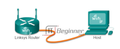
11.5.2.2 Enabling Wireless
To enable wireless connectivity, the wireless mode, SSID, RF channel, and any desired security encryption mechanism must be configured.
First, select the correct wireless mode, as shown in the figure. When selecting the mode, or wireless standard, each mode includes a certain amount of overhead. If all devices on the network use the same standard, selecting the mode associated with that standard limits the amount of overhead incurred. It also increases security by not allowing devices with different standards to connect. However, if devices using different standards need access to the network, mixed mode must be selected. Network performance will decrease due to the additional overhead of supporting all modes.
Next, set the SSID. All devices that wish to participate in the WLAN must use the same SSID. For security purposes, the default SSID should be changed. To allow easy detection of the WLAN by clients, the SSID is broadcast by default. It is possible to disable the broadcast feature of the SSID. If the SSID is not broadcast; wireless clients will need to have this value manually configured.
The choice of RF channel used for the integrated router must be made relative to the other wireless networks around it.
Adjacent wireless networks must use non-overlapping channels in order to optimize throughput. Most access points now offer a choice to allow the router to automatically locate the least congested channel.
Finally, select the encryption mechanism that you prefer and enter a key or passphrase.
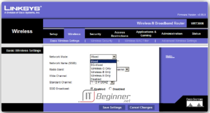
11.5.2.3 Configure a Wireless Client
A wireless host, or client, is defined as any device that contains wireless NIC and wireless client software. This client software allows the hardware to participate in the WLAN. Devices include: some smart phones, laptops, desktop PCs, printers, televisions, game systems, and tablet computers.
In order for a wireless client to connect to the WLAN, the client configuration settings must match that of the wireless router. This includes the SSID, security settings, and channel information (if the channel was manually set). These settings are specified in the client software.
The wireless client software used can be software integrated into the device operating system, or can be a stand-alone, downloadable, wireless utility software specifically designed to interact with the wireless NIC.
Once the client software is configured, verify the link between the client and the AP.
Open the wireless link information screen to display information such as: the connection data rate, connection status, and wireless channel used, as shown in the figure. The Link Information feature, if available, displays the current signal strength and quality of the wireless signal.
In addition, to verifying the wireless connection status, verify that data can actually be transmitted. One of the most common tests for verifying successful data transmission is the ping test. If the ping is successful, data transmission is possible.
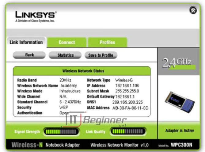
11.5.2.4 Packet Tracer – Configuring a Linksys Router
In this activity, you will configure a Linksys wireless router, allowing remote access to wireless clients as well as connectivity with WPA security.
Packet Tracer – Configuring a Linksys Router Instructions ./.
Packet Tracer – Configuring a Linksys Router – PKA ./.
11.6 Summary
11.6.1 Summary
11.6.1.1 Capstone Project – Design and Build a Small Business Network
Capstone Project
Design and Build a Small Business Network
Use Packet Tracer and a word processing application to complete this activity – 2-3 students per group.
Design and build a network from scratch.
- Your design must include a minimum of one router, one switch, and one PC.
- Fully configure the network – use IPv4 or IPv6 (subnetting must be included as a part of your addressing scheme).
- Verify the network using at least five show commands.
- Secure the network using SSH, secure passwords, and console passwords (minimum).
Create a rubric to use for peer grading – or your Instructor may choose to use the rubric provided with this activity.
Present your Capstone Project to the class – be able to answer questions from your peers and Instructor!
Class Activity – Design and Build a Small Network Instructions ./.

When planning any network consider…
- Cost
- Ports
- Speed
- Expandability
- Manageability
11.6.1.2 Packet Tracer – Skills Integration Challenge
The network administrator has asked you to prepare [[R1Name]] for deployment. Before it can be connected to the network, security measures must be enabled.
Packet Tracer – Skills Integration Challenge Instructions ./.
Packet Tracer – Skills Integration Challenge – PKA ./.
11.6.1.3 Summary
In order to meet user requirements, even small networks require planning and design, as shown in the figure. Planning ensures that all requirements, cost factors, and deployment options are given due consideration. An important part of network design is reliability, scalability, and availability.
Supporting and growing a small network requires being familiar with the protocols and network applications running over the network. Protocol analyzers enable a network professional to quickly compile statistical information about traffic flows on a network. Information gathered by the protocol analyzer is analyzed based on the source and destination of the traffic as well as the type of traffic being sent. This analysis can be used by a network technician to make decisions on how to manage the traffic more efficiently. Common network protocols include: DNS, Telnet, SMTP, POP, DHCP, HTTP, and FTP.
It is a necessity to consider security threats and vulnerabilities when planning a network implementation. All network devices must be secured. This includes routers, switches, end user devices, and even security devices. Networks need to be protected from malicious software such as viruses, Trojan horses, and worms. Antivirus software can detect most viruses and many Trojan horse applications and prevent them from spreading in the network. The most effective way to mitigate a worm attack is to download security updates from the operating system vendor and patch all vulnerable systems.
Networks must also be protected from network attacks. Network attacks can be classified into three major categories: reconnaissance, access attacks, and denial of service. There are several ways to protect a network from network attacks.
- Authentication, authorization, and accounting (AAA, or “triple A”) network security services provide the primary framework to set up access control on a network device. AAA is a way to control who is permitted to access a network (authenticate), what they can do while they are there (authorize), and to watch the actions they perform while accessing the network (accounting).
- A firewall is one of the most effective security tools available for protecting internal network users from external threats. A firewall resides between two or more networks and controls the traffic between them and also helps prevent unauthorized access.
- To protect network devices, it is important to use strong passwords. Also, when accessing network devices remotely, it is highly recommended to enable SSH instead of the unsecured telnet.
After the network has been implemented, a network administrator must be able to monitor and maintain network connectivity. There are several commands available toward this end. For testing network connectivity to local and remote destinations, commands such as ping, telnet, and traceroute are commonly used.
On Cisco IOS devices, the show version command can be used to verify and troubleshoot some of the basic hardware and software components used during the bootup process. To view information for all network interfaces on a router, the show ip interface command is used. The show ip interface brief can also be used to view a more abbreviated output than the show ip interface command. Cisco Discovery Protocol (CDP) is a Cisco-proprietary protocol that runs at the data link layer. Because CDP operates at the data link layer, two or more Cisco network devices, such as routers that support different network layer protocols, can learn about each other even if Layer 3 connectivity does not exist.
Cisco IOS configuration files such as startup-config or running-config should be archived. These files can be saved to a text file or stored on a TFTP server. Some models of routers also have an USB port and a file can be backed up to a USB drive. If needed, these files can be copied to the router and or switch from the TFTP server or USB drive.
The use of networking is not limited to small businesses and large organizations. Another environment that is increasingly taking advantage of networking technology is the home. A home network is very similar to a small-business network. However, most home networks (and many small business networks) do not require high-volume devices, such as dedicated routers and switches. Instead, most home networks use a single multi-function device. For the purpose of this course, multi-function devices will be referred to as integrated routers. Most integrated routers offer both wired switching capabilities and wireless connectivity, and serve as the access point (AP) in the wireless network. To enable wireless connectivity, the wireless mode, SSID, RF channel, and any desired security encryption mechanism must be configured.