Introduction to Networks Instructor Materials – Chapter 6: Network Layer
6.0 Network Layer
6.0.1 Introduction
6.0.1.1 Introduction
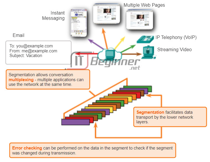
Network applications and services on one end device can communicate with applications and services running on another end device. How is this data communicated across the network in an efficient way?
The protocols of the OSI model network layer specify addressing and processes that enable transport layer data to be packaged and transported. The network layer encapsulation enables data to be passed to a destination within a network (or on another network) with minimum overhead.
This chapter focuses on the role of the network layer. It examines how it divides networks into groups of hosts to manage the flow of data packets within a network. It also covers how communication between networks is facilitated. This communication between networks is called routing.
Upon completion of this chapter you will be able to:
- Describe the purpose of the network layer in data communication.
- Explain why the IPv4 protocol requires other layers to provide reliability.
- Explain the role of the major header fields in the IPv4 and IPv6 packets.
- Explain how host devices use routing tables to direct packets to itself, a local destination, or a default gateway.
- Compare a host routing table to a routing table in a router.
- Describe the common components and interfaces of a router.
- Describe the boot-up process of a Cisco IOS router.
- Configure initial settings on a Cisco IOS router.
- Configure two active interfaces on a Cisco IOS router.
- Configure the default gateway on network devices.
6.0.1.2 Activity – The Road Less Traveled…
The road less traveled…or is it?
During the upcoming weekend, you decide to visit a schoolmate who is currently at home sick. You know his street address but you have never been to his town before. Instead of looking up the address on the map, you decide to take it easy and to simply ask town residents for directions after you arrive by train. The citizens you ask for directions are very helpful. However, they all have an interesting habit. Instead of explaining the entire route to your destination, they all tell you, “Take this road and as soon as you arrive at the nearest crossroad, ask somebody there again.”
Somewhat bemused at this apparent oddity, you follow these instructions and finally arrive, crossroad by crossroad, and road by road, at your friend’s house.
Answer the following questions:
- Would it have made a significant difference if you were told about the whole route or a larger part of the route instead of just being directed to the nearest crossroad?
- Would it have been more helpful to ask about the specific street address or just about the street name? What would happen if the person you asked for directions did not know where the destination street was or directed you through an incorrect road?
- Assume that on your way back home, you again choose to ask residents for directions. Would it be guaranteed that you would be directed via the same route you took to get to your friend’s home? Explain your answer.
- Is it necessary to explain where you depart from when asking directions to an intended destination?
Class Activity – The road less traveled…or is it? Instructions ./.
The Network Layer uses four basic processes…
- Addressing end devices
- Encapsulation
- Routing
- De-encapsulation
6.1 Network Layer Protocols
6.1.1 Network Layer in Communication
6.1.1.1 The Network Layer
The network layer, or OSI Layer 3, provides services to allow end devices to exchange data across the network. To accomplish this end-to-end transport, the network layer uses four basic processes:
Addressing end devices – In the same way that a phone has a unique telephone number, end devices must be configured with a unique IP address for identification on the network. An end device with a configured IP address is referred to as a host.
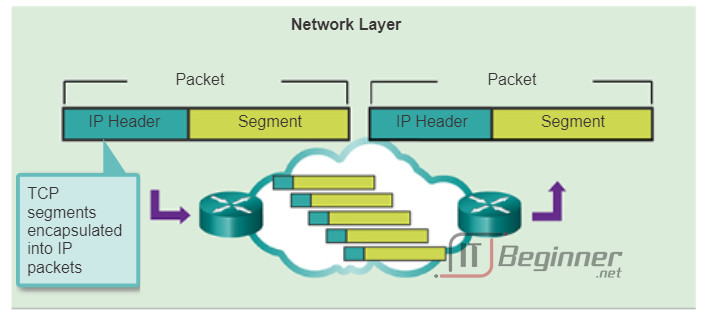
Encapsulation – The network layer receives a protocol data unit (PDU) from the transport layer. In a process called encapsulation, the network layer adds IP header information, such as the IP address of the source (sending) and destination (receiving) hosts. After header information is added to the PDU, the PDU is called a packet.
Routing – The network layer provides services to direct packets to a destination host on another network. To travel to other networks, the packet must be processed by a router. The role of the router is to select paths for and direct packets toward the destination host in a process known as routing. A packet may cross many intermediary devices before reaching the destination host. Each route the packet takes to reach the destination host is called a hop.
De-encapsulation – When the packet arrives at the network layer of the destination host, the host checks the IP header of the packet. If the destination IP address within the header matches its own IP address, the IP header is removed from the packet. This process of removing headers from lower layers is known as de-encapsulation. After the packet is de-encapsulated by the network layer, the resulting Layer 4 PDU is passed up to the appropriate service at the transport layer.
Unlike the transport layer (OSI Layer 4), which manages the data transport between the processes running on each host, network layer protocols specify the packet structure and processing used to carry the data from one host to another host. Operating without regard to the data carried in each packet allows the network layer to carry packets for multiple types of communications between multiple hosts.
The animation in the figure demonstrates the exchange of data.
6.1.1.2 Network Layer Protocols
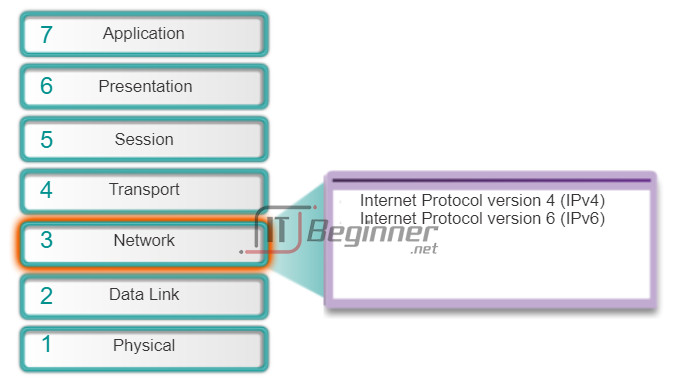
There are several network layer protocols in existence; however, only the following two are commonly implemented as show in the figure:
- Internet Protocol version 4 (IPv4)
- Internet Protocol version 6 (IPv6)
Other legacy network layer protocols that are not widely used include:
- Novell Internetwork Packet Exchange (IPX)
- AppleTalk
- Connectionless Network Service (CLNS/DECNet)
Discussion of these legacy protocols will be minimal.
6.1.2 Characteristics of the IP protocol
6.1.2.1 Characteristics of IP
IP is the network layer service implemented by the TCP/IP protocol suite.
IP was designed as a protocol with low overhead. It provides only the functions that are necessary to deliver a packet from a source to a destination over an interconnected system of networks. The protocol was not designed to track and manage the flow of packets. These functions, if required, are performed by other protocols in other layers.
The basic characteristics of IP are:
- Connectionless – No connection with the destination is established before sending data packets.
- Best Effort (unreliable) – Packet delivery is not guaranteed.
- Media Independent – Operation is independent of the medium carrying the data.
6.1.2.2 IP – Connectionless
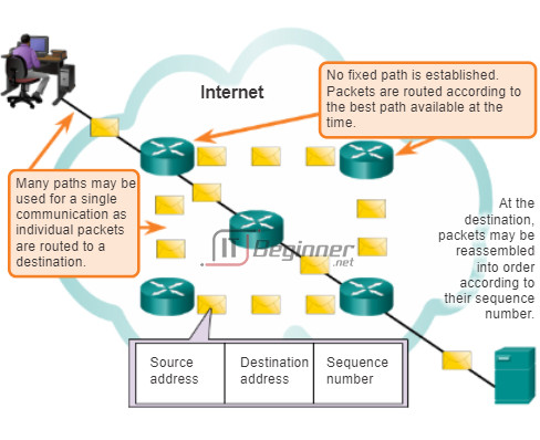
The role of the network layer is to transport packets between hosts while placing as little burden on the network as possible. The network layer is not concerned with, or even aware of, the type of communication contained inside of a packet. IP is connectionless, meaning that no dedicated end-to-end connection is created before data is sent. Connectionless communication is conceptually similar to sending a letter to someone without notifying the recipient in advance.
As shown in Figure 1, the postal service uses the information on a letter to deliver the letter to a recipient. The address on the envelope does not provide information as to whether the receiver is present, whether the letter arrives, or whether the receiver can read the letter. In fact, the postal service is unaware of the information contained within the contents of the packet that it is delivering and, therefore cannot provide any error correction mechanisms.
Connectionless data communications work on the same principle.
IP is connectionless and, therefore, requires no initial exchange of control information to establish an end-to-end connection before packets are forwarded. IP also does not require additional fields in the protocol data unit (PDU) header to maintain an established connection. This process greatly reduces the overhead of IP. However, with no pre-established end-to-end connection, senders are unaware whether destination devices are present and functional when sending packets, nor are they aware if the destination receives the packet, or if they are able to access and read the packet. Figure 2 shows an example of connectionless communication.
[tabs type=”horizontal”]
[tabs_head]
[tab_title]Figure 1[/tab_title]
[tab_title]Figure 2[/tab_title]
[/tabs_head]
[tab]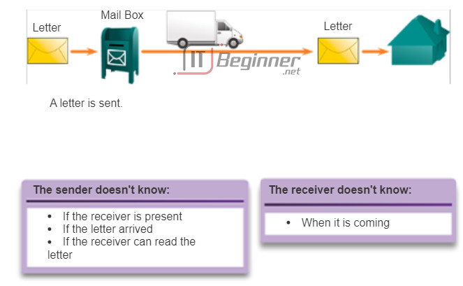 [/tab]
[tab]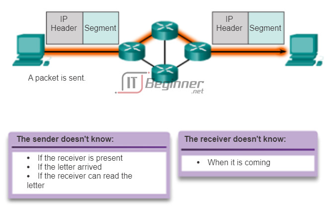 [/tab]
[/tabs]
6.1.2.3 IP – Best Effort Delivery
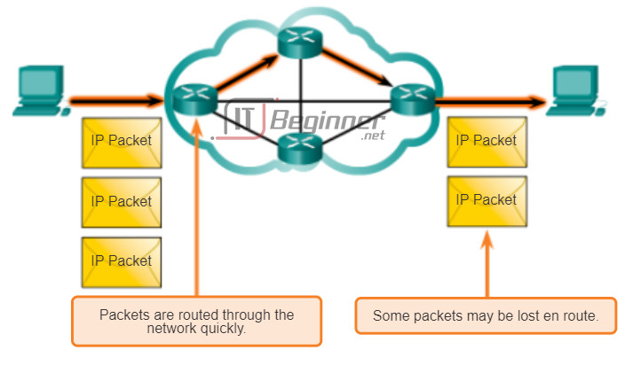
IP is often referred to as an unreliable or best-effort delivery protocol. This does not mean that IP works properly sometimes and does not function well at other times, nor does it mean that it is a poor data communications protocol. Unreliable simply means that IP does not have the capability to manage and recover from undelivered or corrupt packets. This is because while IP packets are sent with information about the location of delivery, it contains no information that can be processed to inform the sender whether delivery was successful. There is no synchronization data included in the packet header for tracking the order of packet delivery. There are also no acknowledgments of packet delivery with IP, and there is no error control data to track whether packets were delivered without corruption. Packets may arrive at the destination corrupted, out of sequence, or not at all. Based on the information provided in the IP header, there is no capability for packet retransmissions if errors such as these occur.
If out-of-order or missing packets create problems for the application using the data, then upper layer services, such as TCP, must resolve these issues. This allows IP to function very efficiently. If reliability overhead were included in IP, then communications that do not require connections or reliability would be burdened with the bandwidth consumption and delay produced by this overhead. In the TCP/IP suite, the transport layer can use either TCP or UDP based on the need for reliability in communication. Leaving the reliability decision to the transport layer makes IP more adaptable and accommodating for different types of communication.
The figure shows an example of IP communications. Connection-oriented protocols, such as TCP, require that control data be exchanged to establish the connection. To maintain information about the connection, TCP also requires additional fields in the PDU header.
6.1.2.4 IP – Media Independent
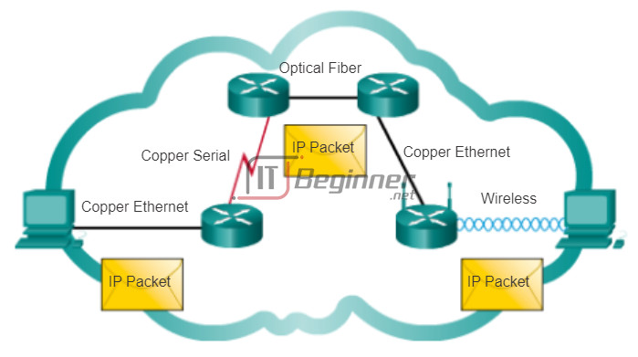
The network layer is also not burdened with the characteristics of the media on which packets are transported. IP operates independently of the media that carry the data at lower layers of the protocol stack. As shown in the figure, any individual IP packet can be communicated electrically over cable, as optical signals over fiber, or wirelessly as radio signals.
It is the responsibility of the OSI data link layer to take an IP packet and prepare it for transmission over the communications medium. This means that the transport of IP packets is not limited to any particular medium.
There is, however, one major characteristic of the media that the network layer considers: the maximum size of the PDU that each medium can transport. This characteristic is referred to as the maximum transmission unit (MTU). Part of the control communication between the data link layer and the network layer is the establishment of a maximum size for the packet. The data link layer passes the MTU value up to the network layer. The network layer then determines how large packets should be.
In some cases, an intermediate device, usually a router, must split up a packet when forwarding it from one medium to a medium with a smaller MTU. This process is called fragmenting the packet or fragmentation.
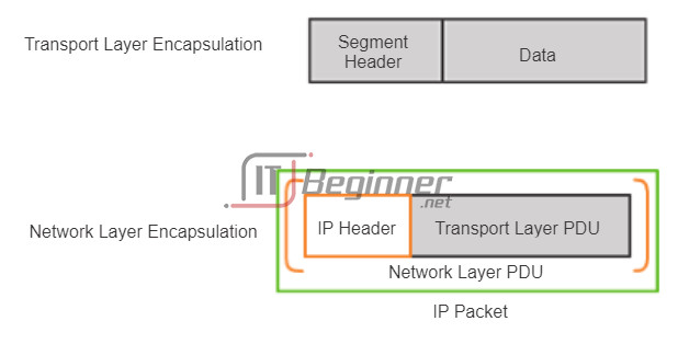
6.1.2.5 Encapsulating IP
IP encapsulates, or packages, the transport layer segment by adding an IP header. This header is used to deliver the packet to the destination host. The IP header remains in place from the time the packet leaves the network layer of the source host until it arrives at the network layer of the destination host.
Figure 1 shows the process for creating the transport layer PDU. Figure 2 shows the subsequent process for creating the network layer PDU.
The process of encapsulating data layer by layer enables the services at the different layers to develop and scale without affecting other layers. This means that transport layer segments can be readily packaged by IPv4 or IPv6 or by any new protocol that might be developed in the future.
Routers can implement these different network layer protocols to operate concurrently over a network to and from the same or different hosts. The routing performed by these intermediate device only considers the contents of the packet header that encapsulates the segment. In all cases, the data portion of the packet, that is, the encapsulated transport layer PDU, remains unchanged during the network layer processes.
[tabs type=”horizontal”]
[tabs_head]
[tab_title]Figure 1[/tab_title]
[tab_title]Figure 2[/tab_title]
[/tabs_head]
[tab]

[/tab]
[tab]
[/tab]
[/tabs]
6.1.2.6 Activity – IP Characteristics
6.1.3 IPv4 Packet
6.1.3.1 IPv4 Packet Header
IPv4 has been in use since 1983 when it was deployed on the Advanced Research Projects Agency Network (ARPANET), which was the precursor to the Internet. The Internet is largely based on IPv4, which is still the most widely-used network layer protocol.
An IPv4 packet has two parts:
- IP Header – Identifies the packet characteristics.
- Payload – Contains the Layer 4 segment information and the actual data.
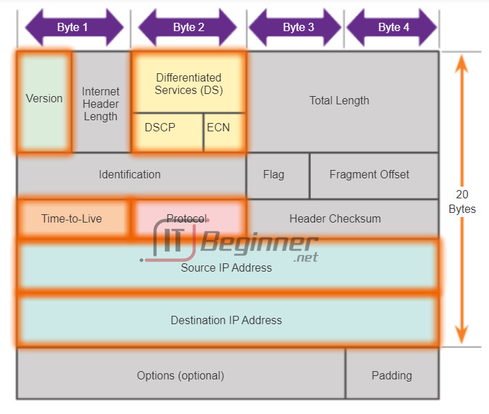
As shown in the figure, an IPv4 packet header consists of fields containing important information about the packet. These fields contain binary numbers which are examined by the Layer 3 process. The binary values of each field identify various settings of the IP packet.
Significant fields in the IPv4 header include:
- Version – Contains a 4-bit binary value identifying the IP packet version. For IPv4 packets, this field is always set to 0100.
- Differentiated Services (DS) – Formerly called the Type of Service (ToS) field, the DS field is an 8-bit field used to determine the priority of each packet. The first 6 bits identify the Differentiated Services Code Point (DSCP) value that is used by a quality of service (QoS) mechanism. The last 2 bits identify the explicit congestion notification (ECN) value that can be used to prevent dropped packets during times of network congestion.
- Time-to-Live (TTL) – Contains an 8-bit binary value that is used to limit the lifetime of a packet. It is specified in seconds but is commonly referred to as hop count. The packet sender sets the initial time-to-live (TTL) value and is decreased by one each time the packet is processed by a router, or hop. If the TTL field decrements to zero, the router discards the packet and sends an Internet Control Message Protocol (ICMP) Time Exceeded message to the source IP address. The traceroute command uses this field to identify the routers used between the source and destination.
- Protocol – This 8-bit binary value indicates the data payload type that the packet is carrying, which enables the network layer to pass the data to the appropriate upper-layer protocol. Common values include ICMP (0x01), TCP (0x06), and UDP (0x11).
- Source IP Address – Contains a 32-bit binary value that represents the source IP address of the packet.
- Destination IP Address – Contains a 32-bit binary value that represents the destination IP address of the packet.
The two most commonly referenced fields are the source and destination IP addresses. These fields identify where the packet is from and where it is going. Typically these addresses do not change while travelling from the source to the destination.
6.1.3.2 IPv4 Header Fields
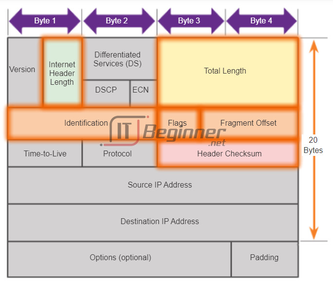
The remaining fields are used to identify and validate the packet, or to reorder a fragmented packet.
The fields used to identify and validate the packet include:
- Internet Header Length (IHL) – Contains a 4-bit binary value identifying the number of 32-bit words in the header. The IHL value varies due to the Options and Padding fields. The minimum value for this field is 5 (i.e., 5×32 = 160 bits = 20 bytes) and the maximum value is 15 (i.e., 15×32 = 480 bits = 60 bytes).
- Total Length – Sometimes referred to as the Packet Length, this 16-bit field defines the entire packet (fragment) size, including header and data, in bytes. The minimum length packet is 20 bytes (20-byte header + 0 bytes data) and the maximum is 65,535 bytes.
- Header Checksum – The 16-bit field is used for error checking of the IP header. The checksum of the header is recalculated and compared to the value in the checksum field. If the values do not match, the packet is discarded.
A router may have to fragment a packet when forwarding it from one medium to another medium that has a smaller MTU. When this happens, fragmentation occurs and the IPv4 packet uses the following fields to keep track of the fragments:
- Identification – This 16-bit field uniquely identifies the fragment of an original IP packet.
- Flags – This 3-bit field identifies how the packet is fragmented. It is used with the Fragment Offset and Identification fields to help reconstruct the fragment into the original packet.
- Fragment Offset – This 13-bit field identifies the order in which to place the packet fragment in the reconstruction of the original unfragmented packet.
Note: The Options and Padding fields are rarely used and beyond the scope of this chapter.
6.1.3.3 Sample IPv4 Headers
Wireshark is a useful network monitoring tool for anyone working with networks and can be used with most labs in the Cisco Certified Network Associate (CCNA) courses for data analysis and troubleshooting. It can be used to view sample values contained in IP header fields.
The three figures contain sample captures of various IP packets:
- Figure 1 displays the contents of packet number 2 in this sample capture. Note that the Source is listed as 192.168.1.109 and the Destination is listed as 192.168.1.1. The middle window contains information about the IPv4 header, such as the header length, total length, and any flags that are set.
- Figure 2 displays the contents of packet number 8 in this sample capture. This is an HTTP packet. Also notice the presence of information beyond the TCP section.
- Finally, Figure 3 displays the contents of packet number 16 in this sample capture. The sample packet is a ping request from host 192.168.1.109 to host 192.168.1.1. Notice how there is no TCP or UDP information because this is an Internet Control Message Protocol (ICMP) packet.
[tabs type=”horizontal”]
[tabs_head]
[tab_title]Figure 1[/tab_title]
[tab_title]Figure 2[/tab_title]
[tab_title]Figure 3[/tab_title]
[/tabs_head]
[tab]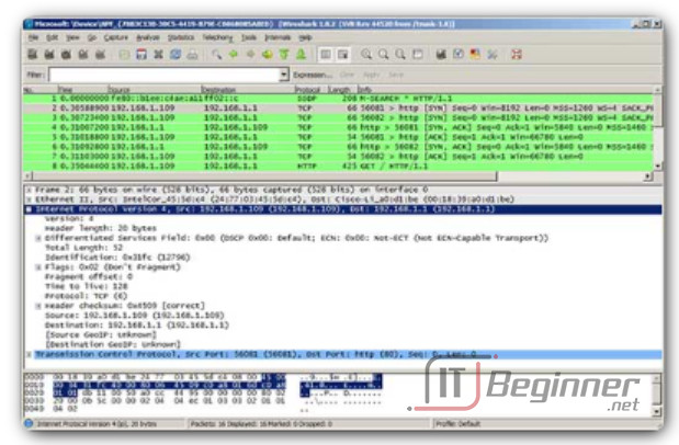 [/tab]
[tab]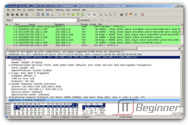 [/tab]
[tab]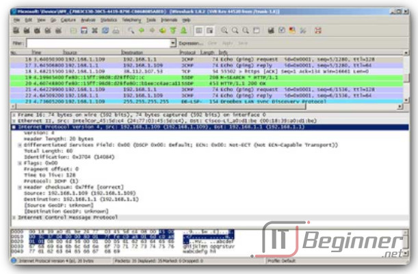 [/tab]
[/tabs]
6.1.3.4 Activity – IPv4 Header Fields
6.1.4 IPv6 Packet
6.1.4.1 Limitations of IPv4
Through the years, IPv4 has been updated to address new challenges. However, even with changes, IPv4 still has three major issues:
- IP address depletion – IPv4 has a limited number of unique public IP addresses available. Although there are approximately 4 billion IPv4 addresses, the increasing number of new IP-enabled devices, always-on connections, and the potential growth of less-developed regions have increased the need for more addresses.
- Internet routing table expansion – A routing table is used by routers to make best path determinations. As the number of servers (nodes) connected to the Internet increases, so too does the number of network routes. These IPv4 routes consume a great deal of memory and processor resources on Internet routers.
- Lack of end-to-end connectivity – Network Address Translation (NAT) is a technology commonly implemented within IPv4 networks. NAT provides a way for multiple devices to share a single public IP address. However, because the public IP address is shared, the IP address of an internal network host is hidden. This can be problematic for technologies that require end-to-end connectivity.

6.1.4.2 Introducing IPv6
In the early 1990s, the Internet Engineering Task Force (IETF) grew concerned about the issues with IPv4 and began to look for a replacement. This activity led to the development of IP version 6 (IPv6). IPv6 overcomes the limitations of IPv4 and is a powerful enhancement with features that better suit current and foreseeable network demands.
Improvements that IPv6 provides include:
- Increased address space – IPv6 addresses are based on 128-bit hierarchical addressing as opposed to IPv4 with 32 bits. This dramatically increases the number of available IP addresses.
- Improved packet handling – The IPv6 header has been simplified with fewer fields. This improves packet handling by intermediate routers and also provides support for extensions and options for increased scalability/longevity.
- Eliminates the need for NAT – With such a large number of public IPv6 addresses, Network Address Translation (NAT) is not needed. Customer sites, from the largest enterprises to single households, can get a public IPv6 network address. This avoids some of the NAT-induced application problems experienced by applications requiring end-to-end connectivity.
- Integrated security – IPv6 natively supports authentication and privacy capabilities. With IPv4, additional features had to be implemented to do this.
The 32-bit IPv4 address space provides approximately 4,294,967,296 unique addresses. Of these, only 3.7 billion addresses are assignable, because the IPv4 addressing system separates the addresses into classes, and reserves addresses for multicasting, testing, and other specific uses.
As shown in the figure, IP version 6 address space provides 340,282,366,920,938,463,463,374,607,431,768,211,456, or 340 undecillion addresses, which is roughly equivalent to every grain of sand on Earth.

6.1.4.3 Encapsulating IPv6
One of the major design improvements of IPv6 over IPv4 is the simplified IPv6 header.
The IPv4 header consists of 20 octets (up to 60 bytes if the Options field is used) and 12 basic header fields, not including the Options field and Padding field.
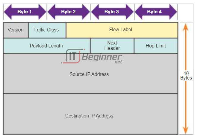
The IPv6 header consists of 40 octets (largely due to the length of the source and destination IPv6 addresses) and 8 header fields (3 IPv4 basic header fields and 5 additional header fields).
Figure 1 shows the IPv4 header structure. As shown in the figure, for IPv6, some fields have remained the same, some fields from the IPv4 header are not used, and some fields have changed names and positions.
In addition, a new field has been added to IPv6 that is not used in IPv4. The IPv6 simplified header is shown in Figure 2.
The IPv6 simplified header offers several advantages over IPv4:
- Better routing efficiency for performance and forwarding-rate scalability
- No requirement for processing checksums
- Simplified and more efficient extension header mechanisms (as opposed to the IPv4 Options field)
- A Flow Label field for per-flow processing with no need to open the transport inner packet to identify the various traffic flows
[tabs type=”horizontal”]
[tabs_head]
[tab_title]IPv4 Header[/tab_title]
[tab_title]IPv6 Header[/tab_title]
[/tabs_head]
[tab]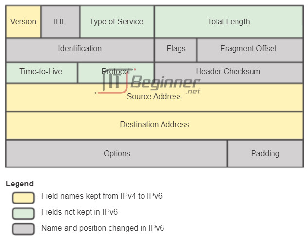 [/tab]
[tab]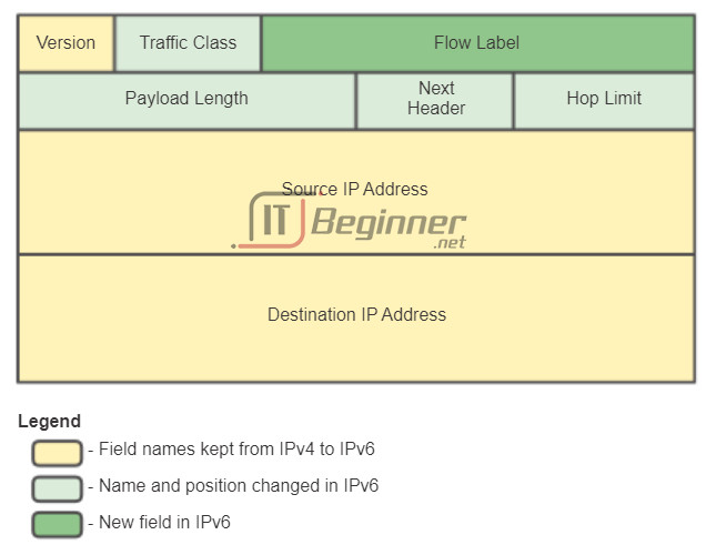 [/tab]
[/tabs]
6.1.4.4 IPv6 Packet Header
The fields in the IPv6 packet header include:
- Version – This field contains a 4-bit binary value identifying the IP packet version. For IPv6 packets, this field is always set to 0110.
- Traffic Class – This 8-bit field is equivalent to the IPv4 Differentiated Services (DS) field. It also contains a 6-bit Differentiated Services Code Point (DSCP) value used to classify packets and a 2-bit Explicit Congestion Notification (ECN) used for traffic congestion control.
- Flow Label – This 20-bit field provides a special service for real-time applications. It can be used to inform routers and switches to maintain the same path for the packet flow so that packets are not reordered.
- Payload Length – This 16-bit field is equivalent to the Total Length field in the IPv4 header. It defines the entire packet (fragment) size, including header and optional extensions.
- Next Header – This 8-bit field is equivalent to the IPv4 Protocol field. It indicates the data payload type that the packet is carrying, enabling the network layer to pass the data to the appropriate upper-layer protocol. This field is also used if there are optional extension headers added to the IPv6 packet.
- Hop Limit: – This 8-bit field replaces the IPv4 TTL field. This value is decremented by one by each router that forwards the packet. When the counter reaches 0 the packet is discarded and an ICMPv6 message is forwarded to the sending host, indicating that the packet did not reach its destination.
- Source Address – This 128-bit field identifies the IPv6 address of the receiving host.
- Destination Address – This 128-bit field identifies the IPv6 address of the receiving host.
An IPv6 packet may also contain extension headers (EH), which provide optional network layer information. Extension headers are optional and are placed between the IPv6 header and the payload. EHs are used for fragmentation, security, to support mobility, and more.
6.1.4.5 Sample IPv6 Header
When viewing IPv6 Wireshark captures, notice that the IPv6 header has markedly fewer fields than an IPv4 header. This makes the IPv6 header easier and quicker for the router to process.
The IPv6 address itself looks very different. Because of the larger 128-bit IPv6 addresses, the hexadecimal numbering system is used to simplify the address representation. IPv6 addresses use colons to separate entries into a series of 16-bit hexadecimal blocks.
Figure 1 displays the contents of packet number 46 in this sample capture. The packet contains the initial message of the TCP 3-way handshake between an IPv6 host and an IPv6 server. Notice the values in the expanded IPv6 header section. Also notice how this is a TCP packet and that it does not contain any other information beyond the TCP section.
Figure 2 displays the contents of packet number 49 in this sample capture. The packet contains the initial HyperText Transfer Protocol (HTTP) GET message to the server. Notice how this is an HTTP packet and that it now contains information beyond the TCP section.
Finally, Figure 3 displays the contents of packet number 1 in this sample capture. The sample packet is an ICMPv6 Neighbor Solicitation message. Notice how there is no TCP or UDP information.
[tabs type=”horizontal”]
[tabs_head]
[tab_title]Figure 1[/tab_title]
[tab_title]Figure 2[/tab_title]
[tab_title]Figure 3[/tab_title]
[/tabs_head]
[tab]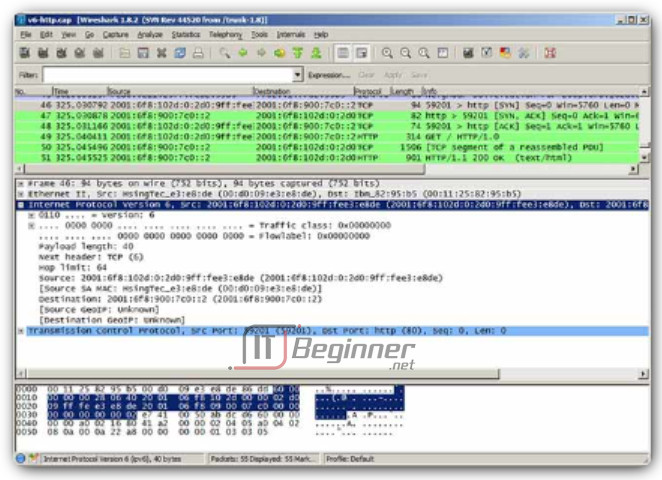 [/tab]
[tab]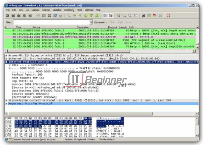 [/tab]
[tab]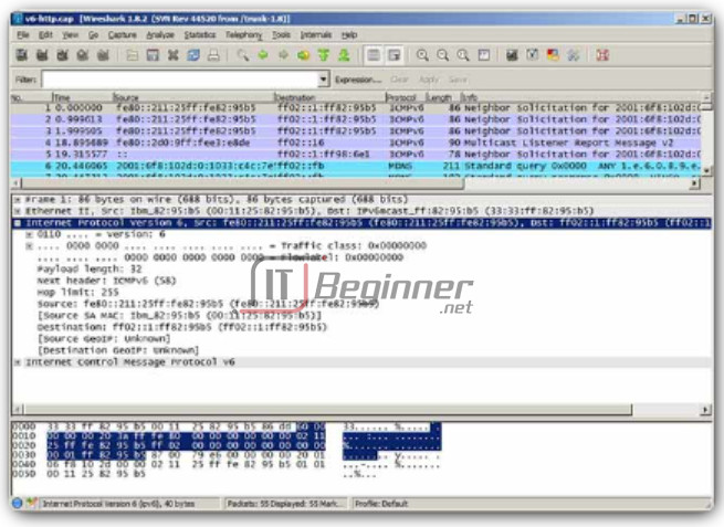 [/tab]
[/tabs]
6.1.4.6 Activity – IPv6 Header Fields
6.2 Routing
6.2.1 How a Host Routes
6.2.1.1 Host Forwarding Decision
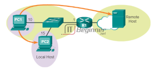
Another role of the network layer is to direct packets between hosts. A host can send a packet to:
- Itself – This is a special IP address of 127.0.0.1 which is referred to as the loopback interface. This loopback address is automatically assigned to a host when TCP/IP is running. The ability for a host to send a packet to itself using network functionality is useful for testing purposes. Any IP within the network 127.0.0.0/8 refers to the local host.
- Local host – This is a host on the same network as the sending host. The hosts share the same network address.
- Remote host – This is a host on a remote network. The hosts do not share the same network address.
Whether a packet is destined for a local host or a remote host is determined by the IP address and subnet mask combination of the source (or sending) device compared to the IP address and subnet mask of the destination device.
In a home or business network you may have several wired and wireless devices interconnected together using an intermediate device such as a LAN switch and/or a wireless access point (WAP). This intermediate device provides interconnections between local hosts on the local network. Local hosts can reach each other and share information without the need of any additional devices. If a host is sending a packet to a device that is configured with the same IP network as the host device, the packet is simply forwarded out of the host interface, through the intermediate device, to the destination device directly.
Of course in most situations we want our devices to be able to connect beyond the local network segment: out to other homes, businesses, and the Internet. Devices that are beyond the local network segment are known as remote hosts. When a source device sends a packet to a remote destination device, then the help of routers and routing is needed. Routing is the process of identifying the best path to a destination. The router connected to the local network segment is referred to as the default gateway.
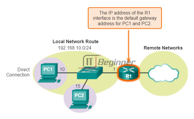
6.2.1.2 Default Gateway
The default gateway is the device that routes traffic from the local network to devices on remote networks. In a home or small business environment, the default gateway is often used to connect the local network to the Internet.
If the host is sending a packet to a device on a different IP network, then the host must forward the packet through the intermediate device to the default gateway. This is because a host device does not maintain routing information, beyond the local network, to reach remote destinations. The default gateway does. The default gateway, which is most often a router, maintains a routing table. A routing table is a data file in RAM that is used to store route information about directly connected network, as well as entries of remote networks the device has learned about. A router uses the information in the routing table to determine the best path to reach those destinations.
So how does a host keep track of whether or not to forward packets to the default gateway? Hosts must maintain their own, local, routing table to ensure that network layer packets are directed to the correct destination network. The local table of the host typically contains:
- Direct connection – This is a route to the loopback interface (127.0.0.1).
- Local network route – The network which the host is connected to is automatically populated in the host routing table.
- Local default route – The default route represents the route that packets must take to reach all remote network addresses. The default route is created when a default gateway address is present on the host. The default gateway address is the IP address of the network interface of the router that is connected to the local network. The default gateway address can be configured on the host manually or learned dynamically.
It is important to note that the default route, and therefore, the default gateway, is only used when a host must forward packets to a remote network. It is not required, nor even needs to be configured, if only sending packets to devices on the local network.
For example, consider a network printer/scanner. If the network printer has an IP address and subnet mask configured, then local hosts can send documents to the printer to be printed. Additionally, the printer can forward documents that have been scanned to any local hosts. As long as the printer is only used locally, a default gateway address is not required. In fact, by not configuring a default gateway address on the printer, you are effectively denying Internet access, which may be a wise security choice. No Internet access means no security risk. While devices, such as printers, may offer the capability to perform automatic updates via the Internet, it is usually easier and more secure to achieve those same updates via a local upload from a secured local host, such as a PC.
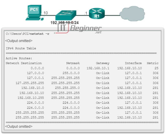
6.2.1.3 IPv4 Host Routing Table
On a Windows host, the route print or netstat -r command can be used to display the host routing table. Both commands generate the same output. The output may seem overwhelming at first, but is fairly simple to understand.
Entering the netstat -r command or the equivalent route print command, displays three sections related to the current TCP/IP network connections:
- Interface List – Lists the Media Access Control (MAC) address and assigned interface number of every network-capable interface on the host including Ethernet, Wi-Fi, and Bluetooth adapters.
- IPv4 Route Table – Lists all known IPv4 routes, including direct connections, local network, and local default routes.
- IPv6 Route Table – Lists all known IPv6 routes, including direct connections, local network, and local default routes.
Note: Command output varies, depending on how the host is configured and the interface types it has.
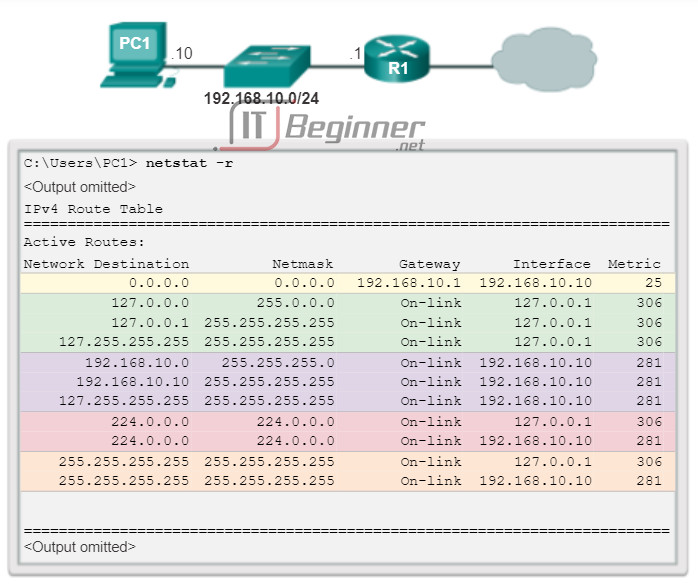
The figure displays the IPv4 Route Table section of the output. Notice the output is divided into five columns which identify:
- Network Destination – Lists the reachable networks.
- Netmask – Lists a subnet mask that informs the host how to determine the network and the host portions of the IP address.
- Gateway – Lists the address used by the local computer to get to a remote network destination. If a destination is directly reachable, it will show as “on-link” in this column.
- Interface – Lists the address of the physical interface used to send the packet to the gateway that is used to reach the network destination.
- Metric – Lists the cost of each route and is used to determine the best route to a destination.
6.2.1.4 IPv4 Host Routing Entries
To help simplify the output, the destination networks can be grouped into five sections as identified by the highlighted areas in the figure:
0.0.0.0
The local default route; that is, all packets with destinations that do not match other specified addresses in the routing table are forwarded to the gateway. Therefore, all non-matching destination routes are sent to the gateway with IP address 192.168.10.1 (R1) exiting from the interface with IP address 192.168.10.10. Note that the final destination address specified in the packet does not change; rather, the host simply knows to forward the packet to the gateway for further processing.
127.0.0.0 – 127.255.255.255
These loopback addresses all relate to the direct connection and provide services to the local host.
192.168.10.0 – 192.168.10.255
These addresses all relate to the host and local network. All packets with destination addresses that fall into this category will exit out of the 192.168.10.10 interface.
- 192.168.10.0 – The local network route address; represents all computers on the 192.168.10.x network.
- 192.168.10.10 – The address of the local host.
- 192.168.10.255 – The network broadcast address; sends messages to all hosts on the local network route.
224.0.0.0
These are special multicast class D addresses reserved for use through either the loopback interface (127.0.0.1) or the host IP address (192.168.10.10).
255.255.255.255
The last two addresses represent the limited broadcast IP address values for use through either the loopback interface (127.0.0.1) or the host IP address (192.168.10.10). These addresses can be used to find a DHCP server before the local IP is determined.
6.2.1.5 Sample IPv4 Host Routing Table
For example, if PC1 wanted to send a packet to 192.168.10.20, it would:
1. Consult the IPv4 Route Table.
2. Match the destination IP address with the 192.168.10.0 Network Destination entry to reveal that the host is on the same network (On-link).
3. PC1 would then send the packet toward the final destination using its local interface (192.168.10.10).
Figure 1 highlights the matched route.
If PC1 wanted to send a packet to a remote host located at 10.10.10.10, it would:
1. Consult the IPv4 Route Table.
2. Find that there is no exact match for the destination IP address.
3. Choose the local default route (0.0.0.0) to reveal that it should forward the packet to the 192.168.10.1 gateway address.
4. PC1 then forwards the packet to the gateway for using its local interface (192.168.10.10). The gateway device then determines the next path for the packet to reach the final destination address of 10.10.10.10.
Figure 2 highlights the matched route.
[tabs type=”horizontal”]
[tabs_head]
[tab_title]Figure 1[/tab_title]
[tab_title]Figure 2[/tab_title]
[/tabs_head]
[tab]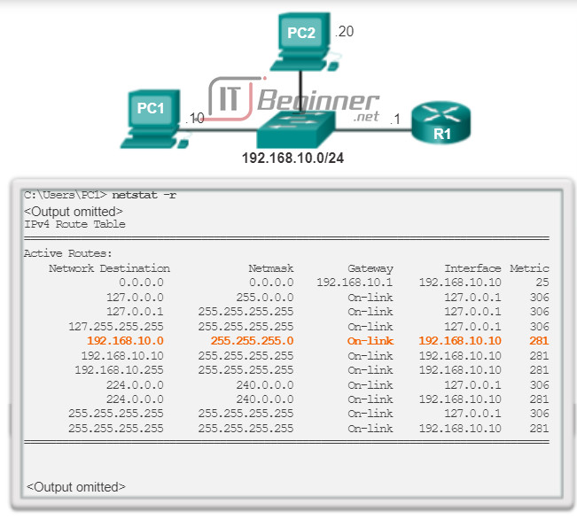 [/tab]
[tab]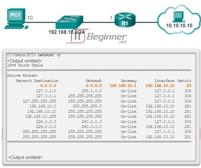 [/tab]
[/tabs]
6.2.1.6 Sample IPv6 Host Routing Table
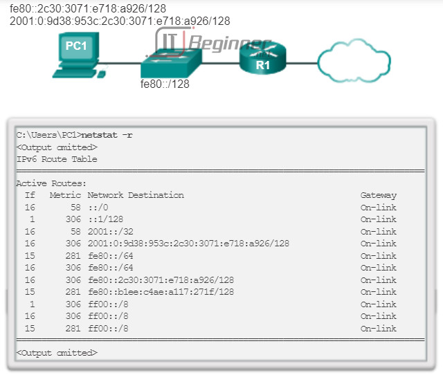
The output of the IPv6 Route Table differs in column headings and format due to the longer IPv6 addresses.
The IPv6 Route Table section displays four columns which identify:
- If – Lists the interface numbers from the Interface List section of the netstat –r command. The interface numbers correspond to the network capable interface on the host, including Ethernet, Wi-Fi, and Bluetooth adapters.
- Metric – Lists the cost of each route to a destination. Lower numbers indicate preferred routes.
- Network Destination – Lists the reachable networks.
- Gateway – Lists the address used by the local host to forward packets to a remote network destination. On-link indicates that the host is currently connected to it.
For example, the figure displays the IPv6 Route section generated by the netstat –r command to reveal the following network destinations:
- ::/0 – This is the IPv6 equivalent of the local default route.
- ::1/128 – This is equivalent to the IPv4 loopback address and provides services to the local host.
- 2001::/32 – This is the global unicast network prefix.
- 2001:0:9d38:953c:2c30:3071:e718:a926/128 – This is the global unicast IPv6 address of the local computer.
- fe80::/64 – This is the local link network route address and represents all computers on the local link IPv6 network.
- fe80::2c30:3071:e718:a926/128 – This is the link local IPv6 address of the local computer.
- ff00::/8 – These are special reserved multicast class D addresses equivalent to the IPv4 224.x.x.x addresses.
Note: Interfaces in IPv6 commonly have two IPv6 addresses: a link local address and a global unicast address. Also, notice that there are no broadcast addresses in IPv6. IPv6 addresses will be discussed further in the next chapter.
6.2.1.7 Activity – Identify Elements of a Host Routing Table Entry
6.2.2 Router Routing Tables
6.2.2.1 Router Packet Forwarding Decision
When a host sends a packet to another host, it will use its routing table to determine where to send the packet. If the destination host is on a remote network, the packet is forwarded to the address of a gateway device.
What happens when a packet arrives on a router interface? The router looks at its routing table to determine where to forward packets.
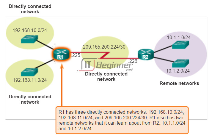
The routing table of a router stores information about:
- Directly-connected routes – These routes come from the active router interfaces. Routers add a directly connected route when an interface is configured with an IP address and is activated. Each of the router’s interfaces is connected to a different network segment. Routers maintain information about the network segments that they are connected to within the routing table.
- Remote routes – These routes come from remote networks connected to other routers. Routes to these networks can either be manually configured on the local router by the network administrator or dynamically configured by enabling the local router to exchange routing information with other routers using dynamic routing protocols.
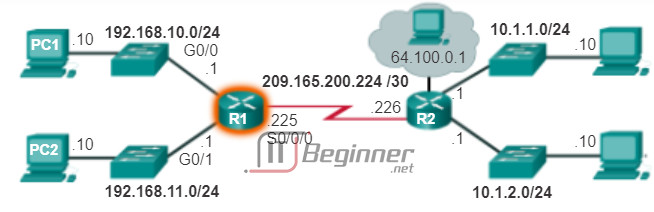
The figure identifies the directly connected networks and remote networks of router R1.
6.2.2.2 IPv4 Router Routing Table
A host routing table includes only information about directly-connected networks. A host requires a default gateway to send packets to a remote destination. The routing table of a router contains similar information but can also identify specific remote networks.
The routing table of a router is similar to the routing table of a host. They both identify the:
- Destination network
- Metric associated with the destination network
- Gateway to get to the destination network
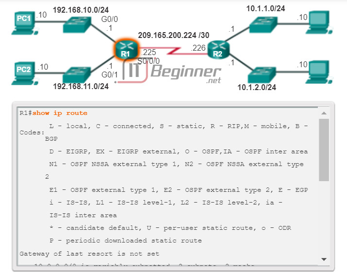
On a Cisco IOS router, the show ip route command can be used to display the routing table of a router. A router also provides additional route information, including how the route was learned, when it was last updated, and which specific interface to use to get to a predefined destination.
When a packet arrives at the router interface, the router examines the packet header to determine the destination network. If the destination network matches a route in the routing table, the router forwards the packet using the information specified in the routing table. If there are two or more possible routes to the same destination, the metric is used to decide which route appears on the routing table.
The figure shows the routing table of R1 in a simple network. Unlike the host routing table, there are no column headings identifying the information contained in a routing table entry. Therefore, it is important to learn the meaning of the different types of information included in each entry.
6.2.2.3 Directly Connected Routing Table Entries
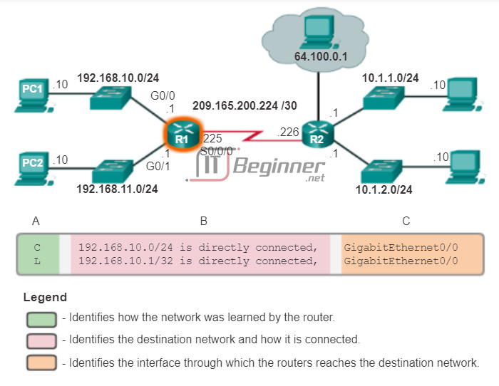
Two routing table entries are automatically created when an active router interface is configured with an IP address and subnet mask. The figure displays the routing table entries on R1 for the directly connected network 192.168.10.0. These entries were automatically added to the routing table when the GigabitEthernet 0/0 interface was configured and activated. The entries contain the following information:
Route Source
The route source is labeled “A” in the figure. It identifies how the route was learned. Directly connected interfaces have two route source codes.
- C – Identifies a directly connected network. Directly connected networks are automatically created when an interface is configured with an IP address and activated.
- L – Identifies that this is a link local route. Link local routes are automatically created when an interface is configured with an IP address and activated.
Destination network
The destination network is labeled “B” in the figure. It identifies the address of the remote network.
Outgoing interface
The outgoing interface is labeled “C” in the figure. It identifies the exit interface to use when forwarding packets to the destination network.
Note: Link local routing table entries did not appear in routing tables prior to IOS Release 15.
A router typically has multiple interfaces configured. The routing table stores information about both directly-connected and remote routes. As with directly connected networks, the route source identifies how the route was learned. For example, common codes for remote networks include:
- S – Identifies that the route was manually created by an administrator to reach a specific network. This is known as a static route.
- D – Identifies that the route was learned dynamically from another router using the Enhanced Interior Gateway Routing Protocol (EIGRP).
- O – Identifies that the route was learned dynamically from another router using the Open Shortest Path First (OSPF) routing protocol.
Note: Other codes are beyond the scope of this chapter.
6.2.2.4 Remote Network Routing Table Entries
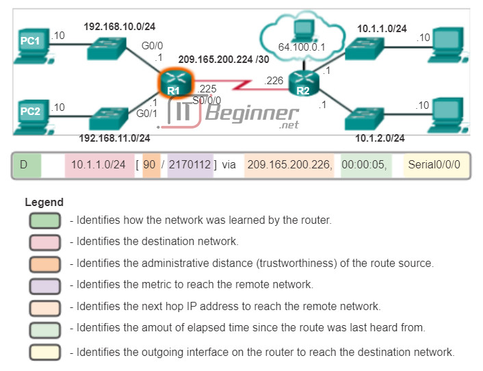
The figure displays a routing table entry on R1 for the route to remote network 10.1.1.0. The entry identifies the following information:
- Route source – Identifies how the route was learned.
- Destination network – Identifies the address of the remote network.
- Administrative distance – Identifies the trustworthiness of the route source.
- Metric – Identifies the value assigned to reach the remote network. Lower values indicate preferred routes.
- Next-hop – Identifies the IP address of the next router to forward the packet.
- Route timestamp – Identifies when the route was last heard from.
- Outgoing interface – Identifies the exit interface to use to forward a packet toward the final destination.
6.2.2.5 Next-Hop Address
A next hop is the address of the device that will process the packet next. For a host on a network, the address of the default gateway (router interface) is the next hop for all packets that must be sent to another network. In the routing table of a router, each route to a remote network lists a next hop.
When a packet destined for a remote network arrives at the router, the router matches the destination network to a route in the routing table. If a match is found, the router forwards the packet to the IP address of the next hop router using the interface identified by the route entry.
A next hop router is the gateway to remote networks.
For example, in the figure, a packet arriving at R1 destined for either the 10.1.1.0 or 10.1.2.0 network is forwarded to the next-hop address 209.165.200.226 using the Serial 0/0/0 interface.
Networks directly connected to a router have no next-hop address, because a router can forward packets directly to hosts on these networks using the designated interface.
Packets cannot be forwarded by the router without a route for the destination network in the routing table. If a route representing the destination network is not in the routing table, the packet is dropped (that is, not forwarded).
However, just as a host can use a default gateway to forward a packet to an unknown destination, a router can also be configured to use a default static route to create a Gateway of Last Resort. The Gateway of Last Resort will be covered in more detail in the CCNA Routing course.
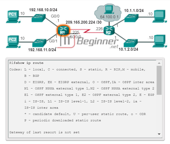
6.2.2.6 Sample Router IPv4 Routing Table
Assume PC1 with IP address 192.168.10.10 wants to send a packet to another host on the same network. PC1 would check the IPv4 route table based on the destination IP address. Then, PC1 would discover that the host is on the same network and simply send it out of its interface (On-link).
Note: R1 is not involved in the transfer of the packet. If PC1 forwards a packet to any network other than its local network, then it must use the services of router R1, and forward the packet to its local default route (192.168.10.1).
The following examples illustrate how a host and a router make packet routing decisions by consulting their respective routing tables:
Example 1: PC1 wants to verify connectivity to its local default gateway at 192.168.10.1 (the router interface):
1. PC1 consults the IPv4 route table based on the destination IP address.
2. PC1 discovers that the host is on the same network and simply sends a ping packet out of its interface (On-link).
3. R1 receives the packet on its Gigabit Ethernet 0/0 (G0/0) interface and looks at the destination IP address.
4. R1 consults its routing table.
5. R1 matches the destination IP address to the L 192.168.10.1/32 routing table entry and discovers that this route points to its own local interface, as shown in Figure 1.
6. R1 opens the remainder of the IP packet and responds accordingly.
Example 2: PC1 wants to send a packet to PC2 (192.168.11.10):
1. PC1 consults the IPv4 route table and discovers that there is no exact match.
2. PC1 therefore uses the all route network (0.0.0.0) and sends the packet using the local default route (192.168.10.1).
3. R1 receives the packet on its Gigabit Ethernet 0/0 (G0/0) interface and looks at the destination IP address (192.168.11.10).
4. R1 consults its routing table and matches the destination IP address to the C 192.168.11.0/24 routing table entry, as shown in Figure 2.
5. R1 forwards the packet out of its directly connected Gigabit Ethernet 0/1 interface (G0/1).
6. PC2 receives the packet and consults its host IPv4 routing table.
7. PC2 discovers that the packet is addressed to it, opens the remainder of the packet, and responds accordingly.
Example 3: PC1 wants to send a packet to 209.165.200.226:
1. PC1 consults the IPv4 route table and discover that there is no exact match.
2. PC1 therefore uses the default route (0.0.0.0/0) and sends the packet using the default gateway (192.168.10.1).
3. R1 receives the packet on its Gigabit Ethernet 0/0 (G0/0) interface and looks at the destination IP address (209.165.200.226).
4. R1 consults its routing table and matches the destination IP address to the C 209.165.200.224/30 routing table entry, as shown in Figure 3.
5. R1 forwards the packet out of its directly connected Serial 0/0/0 interface (S0/0/0).
Example 4: PC1 wants to send a packet to the host with IP address 10.1.1.10:
1. PC1 consults the IPv4 route table and discovers that there is no exact match.
2. PC1 therefore uses the all route network (0.0.0.0) and sends it to its local default route (192.168.10.1).
3. R1 receives the packet on its Gigabit Ethernet 0/0 (G0/0) interface and looks at the destination IP address (10.1.1.10).
4. R1 consults its routing table and matches the destination IP address to the D 10.1.1.0/24 routing table entry, as shown in Figure 4.
5. R1 discovers it has to send the packet to the next-hop address 209.165.200.226.
6. R1 again consults its routing table and matches the destination IP address to the C 209.165.200.224/30 routing table entry, as shown in Figure 4.
7. R1 forwards the packet out of its directly connected Serial 0/0/0 interface (S0/0/0).
[tabs type=”horizontal”]
[tabs_head]
[tab_title]1[/tab_title]
[tab_title]2[/tab_title]
[tab_title]3[/tab_title]
[tab_title]4[/tab_title]
[/tabs_head]
[tab]
R1#show ip route
Codes:	 L - local, C - connected, S - static, R - RIP,M - mobile,
         B - BGP
         D - EIGRP, EX - EIGRP external, O - OSPF,IA - OSPF inter area
         N1 - OSPF NSSA external type 1,N2 - OSPF NSSA external type 2
         E1 - OSPF external type 1, E2 - OSPF external type 2, E - EGP
         i - IS-IS, L1 - IS-IS level-1, L2 - IS-IS level-2, ia -
         IS-IS inter area
         * - candidate default, U - per-user static route, o - ODR
         P - periodic downloaded static route

Gateway of last resort is 209.165.200.226 to network 0.0.0.0
   10.0.0.0/8 is variably subnetted, 2 subnets, 2 masks
D	 10.1.1.0/24 [90/2170112] via 209.165.200.226, 01:13:55,
 Serial0/0/0
D	 10.1.1.0/24 [90/2170112] via 209.165.200.226, 01:13:55,
 Serial0/0/0
192.168.10.0/24 is variably subnetted, 2 subnets, 3 masks
C	 192.168.10.0/24 is directly connected, GigabitEthernet0/0
L	 192.168.10.1/32 is directly connected, GigabitEthernet0/0
192.168.11.0/24 is variably subnetted, 2 subnets, 3 masks
C	 192.168.11.0/24 is directly connected, GigabitEthernet0/1
L	 192.168.10.1/32 is directly connected, GigabitEthernet0/1
209.165.200.0/24 is variably subnetted, 2 subnets, 3 masks
C	 209.165.200.224/30 is directly connected, Serial0/0/0
L	 209.165.200.225/32 is directly connected, Serial0/0/0
S*	0.0.0.0/0 [1/0] via 209.165.200.226
[/tab]
[tab]
R1#show ip route
Codes:	 L - local, C - connected, S - static, R - RIP,M - mobile,
         B - BGP
         D - EIGRP, EX - EIGRP external, O - OSPF,IA - OSPF inter area
         N1 - OSPF NSSA external type 1,N2 - OSPF NSSA external type 2
         E1 - OSPF external type 1, E2 - OSPF external type 2, E - EGP
         i - IS-IS, L1 - IS-IS level-1, L2 - IS-IS level-2, ia -
         IS-IS inter area
         * - candidate default, U - per-user static route, o - ODR
         P - periodic downloaded static route

Gateway of last resort is 209.165.200.226 to network 0.0.0.0
10.0.0.0/8 is variably subnetted, 2 subnets, 2 masks
D	 10.1.1.0/24 [90/2170112] via 209.165.200.226, 01:13:55,
 Serial0/0/0
D	 10.1.1.0/24 [90/2170112] via 209.165.200.226, 01:13:55,
 Serial0/0/0
192.168.10.0/24 is variably subnetted, 2 subnets, 3 masks
C	 192.168.10.0/24 is directly connected, GigabitEthernet0/0
L	 192.168.10.1/32 is directly connected, GigabitEthernet0/0
192.168.11.0/24 is variably subnetted, 2 subnets, 3 masks
C	 192.168.11.0/24 is directly connected, GigabitEthernet0/1
L	 192.168.10.1/32 is directly connected, GigabitEthernet0/1
209.165.200.0/24 is variably subnetted, 2 subnets, 3 masks
C	 209.165.200.224/30 is directly connected, Serial0/0/0
L	 209.165.200.225/32 is directly connected, Serial0/0/0
S*	0.0.0.0/0 [1/0] via 209.165.200.226
[/tab]
[/tabs]
6.2.2.7 Activity – Identify Elements of a Router Routing Table Entry
6.2.2.8 Lab – View Host Routing Tables
In this lab, you will complete the following objectives:
- Part 1: Access the Host Routing Table
- Part 2: Examine IPv4 Host Routing Table Entries
- Part 3: Examine IPv6 Host Routing Table Entries
Lab – Viewing Host Routing Tables ./.
6.3 Routers
6.3.1 Anatomy of a Router
6.3.1.1 A Router is a Computer
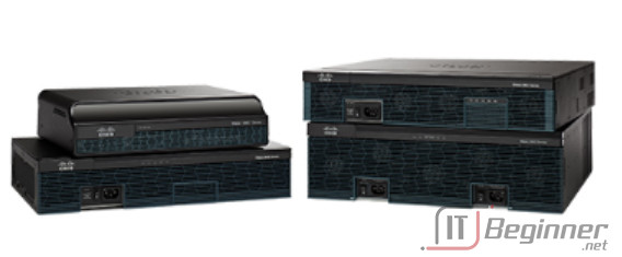
There are many types of infrastructure routers available. In fact, Cisco routers are designed to address the needs of:
- Branch – Teleworkers, small business, and medium-size branch sites. Includes Cisco 800, 1900, 2900, and 3900 Integrated Series Routers (ISR) G2 (2nd generation).
- WAN – Large businesses, organizations, and enterprises. Includes the Cisco Catalyst 6500 Series Switches and the Cisco Aggregation Service Router (ASR) 1000.
- Service Provider – Large service providers. Includes Cisco ASR 1000, Cisco ASR 9000, Cisco XR 12000, Cisco CRS-3 Carrier Routing System, and 7600 Series routers.
The focus of CCNA certification is on the branch family of routers. The figure displays the Cisco 1900, 2900, and 3900 ISR G2 family of routers.
Regardless of their function, size or complexity, all router models are essentially computers. Just like computers, tablets, and smart devices, routers also require:
- Operating systems (OS)
- Central processing units (CPU)
- Random-access memory (RAM)
- Read-only memory (ROM)
A router also has special memory that includes Flash and nonvolatile random-access memory (NVRAM).
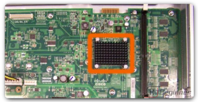
6.3.1.2 Router CPU and OS
Like all computers, tablets, and smart devices, Cisco devices require a CPU to execute OS instructions, such as system initialization, routing functions, and switching functions.
The CPU requires an OS to provide routing and switching functions. The Cisco Internetwork Operating System (IOS) is the system software used for most Cisco devices regardless of the size and type of the device. It is used for routers, LAN switches, small wireless access points, large routers with dozens of interfaces, and many other devices.
The highlighted component in the figure is the CPU of a Cisco 1941 router with the heatsink attached.
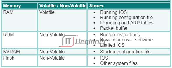
6.3.1.3 Router Memory
A router has access to four types of memory: RAM, ROM, NVRAM, and Flash.
RAM
RAM is used to store various applications and processes including:
- Cisco IOS – The IOS is copied into RAM during bootup.
- Running configuration file – This is the configuration file that stores the configuration commands that the router IOS is currently using. It is also known as the running-config.
- IP routing table – This file stores information about directly-connected and remote networks. It is used to determine the best path to use to forward packets.
- ARP cache – This cache contains the IPv4 address to MAC address mappings, similar to the Address Resolution Protocol (ARP) cache on a PC. The ARP cache is used on routers that have LAN interfaces, such as Ethernet interfaces.
- Packet buffer – Packets are temporarily stored in a buffer when received on an interface or before they exit an interface.
Like computers, Cisco routers actually use dynamic random-access memory (DRAM). DRAM is a very common kind of RAM that stores the instructions and data needed to be executed by the CPU. Unlike ROM, RAM is volatile memory and requires continual power to maintain its information. It loses all of its content when the router is powered down or restarted.
By default 1941 routers come with 512 MB of DRAM soldered on the main system board (onboard) and one dual in-line memory module (DIMM) slot for memory upgrades of up to an additional 2.0 GB. Cisco 2901, 2911, and 2921 models come with 512 MB of onboard DRAM. Note that first generation ISRs and older Cisco routers do not have onboard RAM.
ROM
Cisco routers use ROM to store:
- Bootup instructions – Provides the startup instructions.
- Basic diagnostic software – Performs the power-on self-test (POST) of all components.
- Limited IOS – Provides a limited backup version of the OS, in case the router cannot load the full featured IOS.
ROM is firmware embedded on an integrated circuit inside the router and does not lose its contents when the router loses power or is restarted.
NVRAM
NVRAM is used by the Cisco IOS as permanent storage for the startup configuration file (startup-config). Like ROM, NVRAM does not lose its contents when power is turned off.
Flash Memory
Flash memory is non-volatile computer memory used as permanent storage for the IOS and other system related files. The IOS is copied from flash into RAM during the bootup process.
Cisco 1941 routers come with two external Compact Flash slots. Each slot can support high-speed storage densities upgradeable to 4GB in density.
The figure summarizes the four types of memory.
6.3.1.4 Inside a Router
Although there are several different types and models of routers, every router has the same general hardware components.
The figure shows the inside of a Cisco 1841 first generation ISR. Click the components to see a brief description of the components.
Note that the figure also includes highlights of other components found in a router, such as the power supply, cooling fan, heat shields, and an advanced integration module (AIM), which are beyond the scope of this chapter.
Note: A networking professional should be familiar with and understand the function of the main internal components of a router, rather than the exact location of those components inside a specific router. Depending on the model, those components are located in different places inside the router.
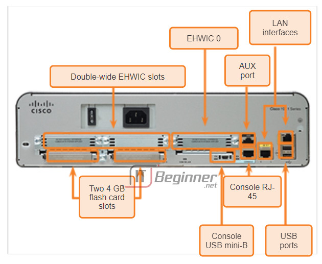
6.3.1.5 Router Backplane
A Cisco 1941 router includes the following connections:
- Console ports – Two console ports for the initial configuration and command-line interface (CLI) management access using a regular RJ-45 port and a new USB Type-B (mini-B USB) connector.
- AUX port – An RJ-45 port for remote management access; this is similar to the Console port.
- Two LAN interfaces – Two Gigabit Ethernet interfaces for LAN access.
- Enhanced high-speed WAN interface card (EHWIC) slots – Two slots that provide modularity and flexibility by enabling the router to support different types of interface modules, including Serial, digital subscriber line (DSL), switch port, and wireless.
The Cisco 1941 ISR also has storage slots to support expanded capabilities. Dual-compact flash memory slots are capable of supporting a 4 GB compact flash card each for increased storage space. Two USB host ports are included for additional storage space and secure token capability.
Compact flash can store the Cisco IOS software image, log files, voice configuration files, HTML files, backup configurations, or any other file needed for the system. By default, only slot 0 is populated with a compact flash card from the factory, and it is the default boot location.
The figure identifies the location of these connections and slots.
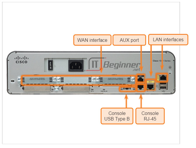
6.3.1.6 Connecting to a Router
Cisco devices, routers, and switches typically interconnect many devices. For this reason, these devices have several types of ports and interfaces. These ports and interfaces are used to connect cables to the device.
The connections on a Cisco router can be grouped into two categories:
- Management ports – These are the console and auxiliary ports used to configure, manage, and troubleshoot the router. Unlike LAN and WAN interfaces, management ports are not used for packet forwarding.
- Inband Router interfaces – These are the LAN and WAN interfaces configured with IP addressing to carry user traffic. Ethernet interfaces are the most common LAN connections, while common WAN connections include serial and DSL interfaces.
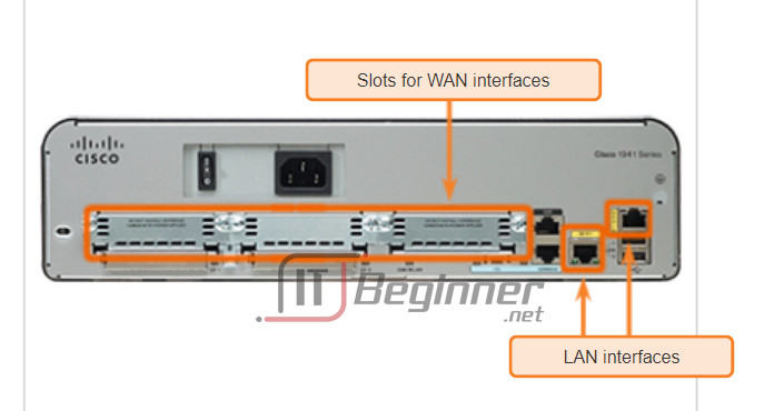
The figure highlights the ports and interfaces of a Cisco 1941 ISR G2 router.
Like many networking devices, Cisco devices use light emitting diode (LED) indicators to provide status information. An interface LED indicates the activity of the corresponding interface. If an LED is off when the interface is active and the interface is correctly connected, this may be an indication of a problem with that interface. If an interface is extremely busy, its LED is always on.
6.3.1.7 LAN and WAN Interfaces
Similar to a Cisco switch, there are several ways to access the CLI environment on a Cisco router. The most common methods are:
- Console – Uses a low speed serial or USB connection to provide direct connect, out-of-band management access to a Cisco device.
- Telnet or SSH – Two methods for remotely accessing a CLI session across an active network interface.
- AUX port – Used for remote management of the router using a dial-up telephone line and modem.
The console and AUX port are located on the router.
In addition to these ports, routers also have network interfaces to receive and forward IP packets. Routers have multiple interfaces that are used to connect to multiple networks. Typically, the interfaces connect to various types of networks, which mean that different types of media and connectors are required.
Every interface on the router is a member or host on a different IP network. Each interface must be configured with an IP address and subnet mask of a different network. The Cisco IOS does not allow two active interfaces on the same router to belong to the same network.
Router interfaces can be grouped into two categories:
- Ethernet LAN interfaces – Used for connecting cables that terminate with LAN devices, such as computers and switches. This interface can also be used to connect routers to each other. Several conventions for naming Ethernet interfaces are popular: the older Ethernet, FastEthernet, and Gigabit Ethernet. The name used depends on the device type and model.
- Serial WAN interfaces – Used for connecting routers to external networks, usually over a larger geographical distance. Similar to LAN interfaces, each serial WAN interface has its own IP address and subnet mask, which identifies it as a member of a specific network.
The figure shows the LAN Interfaces and serial interfaces on the router.
6.3.1.8 Activity – Identify Router Components
6.3.1.9 Lab – Exploring Router Physical Characteristics
In this lab, you will complete the following objectives:
- Part 1: Examine Router External Characteristics
- Part 2: Examine Router Internal Characteristics Using Show Commands
Lab – Exploring Router Physical Characteristics ./.
6.3.1.10 Packet Tracer – Exploring Internetworking Devices
In this activity, you will explore the different options available on internetworking devices. You will also be required to determine which options provide the necessary connectivity when connecting multiple devices. Finally, you will add the correct modules and connect the devices.
Packet Tracer – Exploring Internetworking Devices Instructions ./.
Packet Tracer – Exploring Internetworking Devices – PKA ./.
6.3.2 Router Boot-up
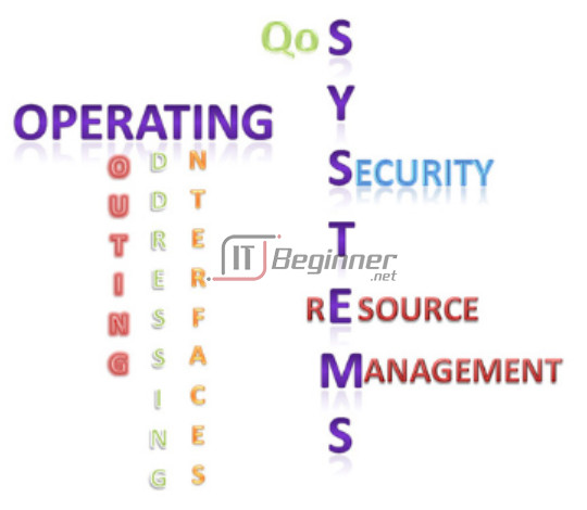
6.3.2.1 Cisco IOS
The Cisco IOS operational details vary on different internetworking devices, depending on the device’s purpose and feature set. However, Cisco IOS for routers provides the following:
- Addressing
- Interfaces
- Routing
- Security
- QoS
- Resources Management
The IOS file itself is several megabytes in size and similar to Cisco IOS switches, is stored in flash memory. Using flash allows the IOS to be upgraded to newer versions or to have new features added. During bootup, the IOS is copied from flash memory into RAM. DRAM is much faster than flash; therefore, copying the IOS into RAM increases the performance of the device.
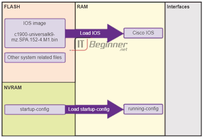
6.3.2.2 Bootset Files
As shown in the figure, a router loads the following two files into RAM when it is booted:
- IOS image file – The IOS facilitates the basic operation of the device’s hardware components. The IOS image file is stored in flash memory.
- Startup configuration file – The startup configuration file contains commands that are used to initially configure a router and create the running configuration file stored in in RAM. The startup configuration file is stored in NVRAM. All configuration changes are stored in the running configuration file and are implemented immediately by the IOS.
The running configuration is modified when the network administrator performs device configuration. When changes are made to the running-config file, it should be saved to NVRAM as the startup configuration file, in case the router is restarted or loses power.
6.3.2.3 Router Bootup Process
There are three major phases to the bootup process that is shown in Figure 1:
1. Perform the POST and load the bootstrap program.
2. Locate and load the Cisco IOS software.
3. Locate and load the startup configuration file or enter setup mode.
1. Performing POST and Load Bootstrap Program (Figure 2)
The Power-On Self Test (POST) is a common process that occurs on almost every computer during bootup. The POST process is used to test the router hardware. When the router is powered on, software on the ROM chip conducts the POST. During this self-test, the router executes diagnostics from ROM on several hardware components, including the CPU, RAM, and NVRAM. After the POST has been completed, the router executes the bootstrap program.
After the POST, the bootstrap program is copied from ROM into RAM. Once in RAM, the CPU executes the instructions in the bootstrap program. The main task of the bootstrap program is to locate the Cisco IOS and load it into RAM.
Note: At this point, if you have a console connection to the router, you begin to see output on the screen.
2. Locating and Loading Cisco IOS (Figure 3)
The IOS is typically stored in flash memory and is copied into RAM for execution by the CPU. During self-decompression of the IOS image file, a string of pounds signs (#) will be displayed.
If the IOS image is not located in flash, then the router may look for it using a TFTP server. If a full IOS image cannot be located, a scaled-down version of the IOS is copied from ROM into RAM. This version of IOS is used to help diagnose any problems and can be used to load a complete version of the IOS into RAM.
3. Locating and Loading the Configuration File (Figure 4)
The bootstrap program then searches for the startup configuration file (also known as startup-config), in NVRAM. This file has the previously saved configuration commands and parameters. If it exists, then it is copied into RAM as the running configuration file, running-config. The running-config file contains interface addresses, starts routing processes, configures router passwords, and defines other characteristics of the router.
If the startup-config file does not exist in NVRAM, the router may search for a Trivial File Transfer Protocol (TFTP) server. If the router detects that it has an active link to another configured router, it sends a broadcast searching for a configuration file across the active link.
If a TFTP server is not found, then the router displays the setup mode prompt. Setup mode is a series of questions prompting the user for basic configuration information. Setup mode is not intended to be used to enter complex router configurations, and it is not commonly used by network administrators.
Note: Setup mode is not used in this course to configure the router. When prompted to enter setup mode, always answer no. If you answer yes and enter setup mode, press Ctrl+C at any time to terminate the setup process.
[tabs type=”horizontal”]
[tabs_head]
[tab_title]Figure 1[/tab_title]
[tab_title]Figure 2[/tab_title]
[tab_title]Figure 3[/tab_title]
[tab_title]Figure 4[/tab_title]
[/tabs_head]
[tab]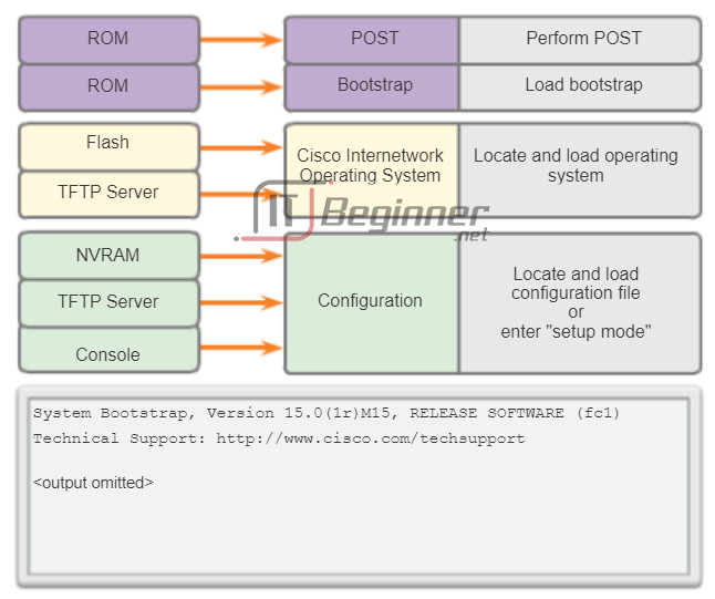 [/tab]
[tab]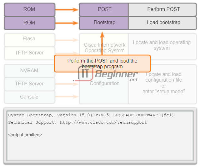 [/tab]
[tab]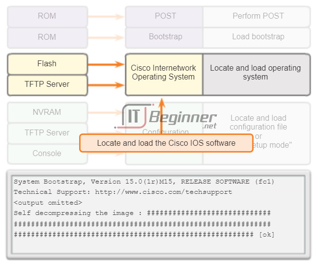 [/tab]
[tab]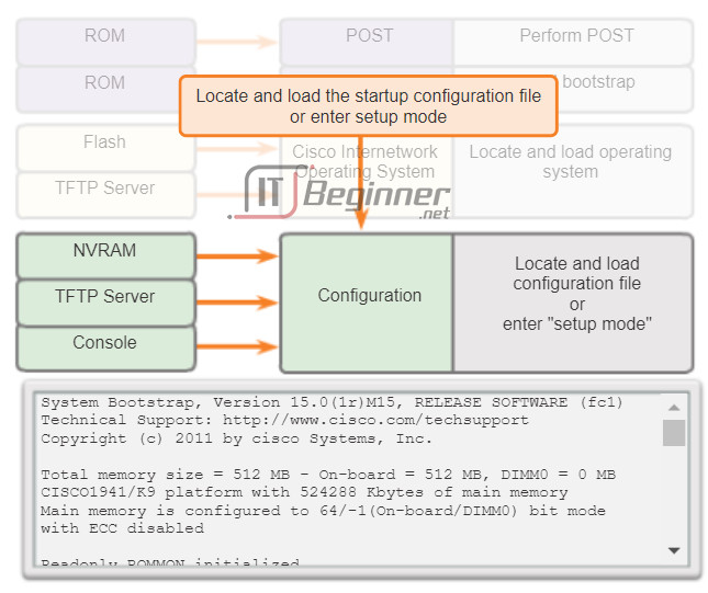 [/tab]
[/tabs]
6.3.2.4 Show Version Output
You can use the show version command to verify and troubleshoot some of the basic hardware and software components of the router. The command displays information about the version of the Cisco IOS software currently running on the router, the version of the bootstrap program, and information about the hardware configuration, including the amount of system memory.
The output from the show version command includes:
- IOS version – Version of the Cisco IOS software in RAM and that is being used by the router.
- ROM Bootstrap Program – Displays the version of the system bootstrap software, stored in ROM that was initially used to boot up the router.
- Location of IOS – Displays where the bootstrap program is located and loaded the Cisco IOS, and the complete filename of the IOS image.
- CPU and Amount of RAM – The first part of this line displays the type of CPU on this router. The last part of this line displays the amount of DRAM. Some series of routers, like the Cisco 1941 ISR, use a fraction of DRAM as packet memory. Packet memory is used for buffering packets. To determine the total amount of DRAM on the router, add both numbers.
- Interfaces – Displays the physical interfaces on the router. In this example, the Cisco 1941 ISR has two Gigabit Ethernet interfaces and two low-speed serial interfaces.
- Amount of NVRAM and Flash – This is the amount of NVRAM and the amount of flash memory on the router. NVRAM is used to store the startup-config file and flash is used to permanently store the Cisco IOS.
The last line of the show version command displays the current, configured value of the software configuration register in hexadecimal. If there is a second value displayed in parentheses, it denotes the configuration register value that is used during the next reload.
The configuration register has several uses, including password recovery. The factory default setting for the configuration register is 0x2102. This value indicates that the router attempts to load a Cisco IOS software image from flash memory and load the startup configuration file from NVRAM.
Router#show version

Cisco IOS Software, C1900 Software (C1900-UNIVERSALK9-M),
Version 15.2(4)M1, RELEASE SOFTWARE (fc1)

Technical Support: http://www.cisco.com/techsupport
Copyright (c) 1986-2012 by Cisco Systems, Inc.
Compiled Thu 26-Jul-12 19:34 by prod_rel_team

ROM: System Bootstrap, Version 15.0(1r)M15, RELEASE SOFTWARE (fc1)

Router uptime is 10 hours, 9 minutes
System returned to ROM by power-on
System image file is "flash0:c1900-universalk9-mz.SPA.152-4.M1.bin"
Last reload type: Normal Reload
Last reload reason: power-on

<Output omitted>

Cisco CISCO1941/K9 (revision 1.0) with 446464K/77824K bytes of memory.
Processor board ID FTX1636848Z
2 Gigabit Ethernet interfaces
2 Serial(sync/async) interfaces
1 terminal line
DRAM configuration is 64 bits wide with parity disabled.
255K bytes of non-volatile configuration memory.
250880K bytes of ATA System CompactFlash 0 (Read/Write)

<Output omitted>

Technology Package License Information for Module:'c1900'

---------------	----------------------------	------------------
Technology	Technology-package	Technology-package
Current	Type	Next reboot
---------------	----------------------------	------------------
ipbase	ipbasek9	Permanent	ipbasek9
security	None	None	None
data	None	None	None


Configuration register is 0x2142 (will be 0x2102 at next reload)

Router#
6.3.2.5 Video Demonstration – The Router Boot Process
6.3.2.6 Activity – The Router Boot Process
6.4 Configuring a Cisco Router
6.4.1 Configure Initial Settings
6.4.1.1 Router Configuration Steps
Cisco routers and Cisco switches have many similarities. They support a similar modal operating system, support similar command structures, and support many of the same commands. In addition, both devices have identical initial configuration steps when implementing them in a network.
Similar to configuring a switch, the following steps should be completed when configuring initial settings on a router:
1. Assign a device name using the hostname global configuration command. (Figure 1)
2. Set passwords. (Figure 2)
- Secure privileged EXEC mode access using the enable secret command.
- Secure EXEC mode access using the login command on the console port, and the password command to set the password.
- Secure virtual access similar to securing EXEC access mode, except on the Virtual Teletype (VTY) port.
- Use the service password-encryption global configuration command to prevent passwords from displaying as plain text in the configuration file.
3. Provide legal notification using the banner motd (message of the day [MOTD]) global configuration command. (Figure 3)
4. Save the configuration using the copy run start command. (Figure 4)
5. Verify the configuration using the show run command.
Figure 5 is a syntax checker that allows you to practice these configuration steps.
[tabs type=”horizontal”]
[tabs_head]
[tab_title]Figure 1[/tab_title]
[tab_title]Figure 2[/tab_title]
[tab_title]Figure 3[/tab_title]
[tab_title]Figure 4[/tab_title]
[tab_title]Figure 5[/tab_title]
[/tabs_head]
[tab]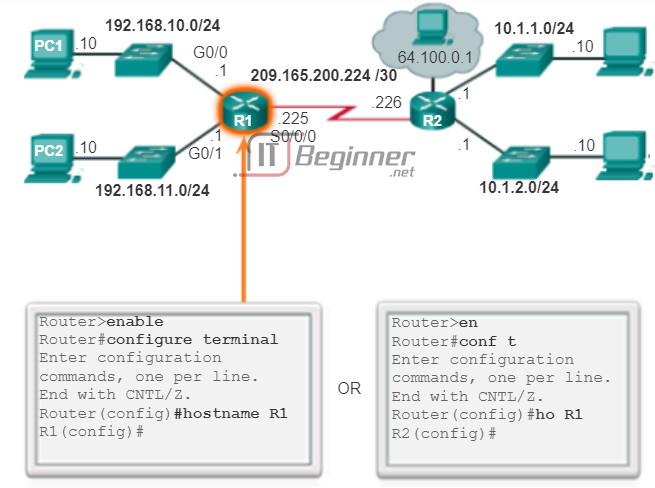 [/tab]
[tab]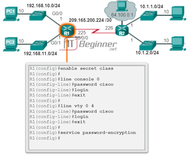 [/tab]
[tab]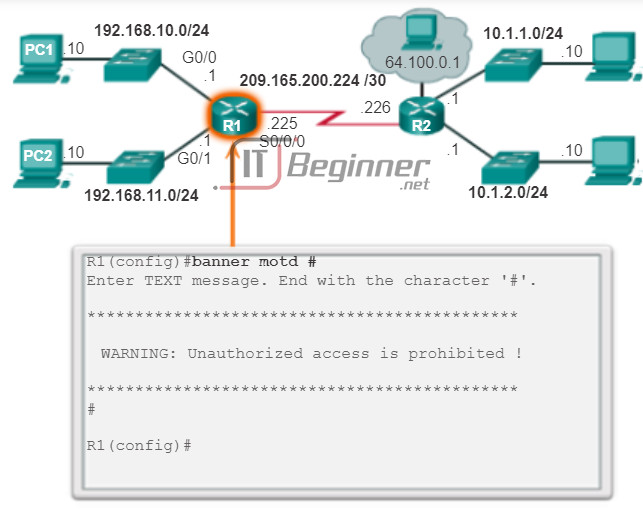 [/tab]
[tab]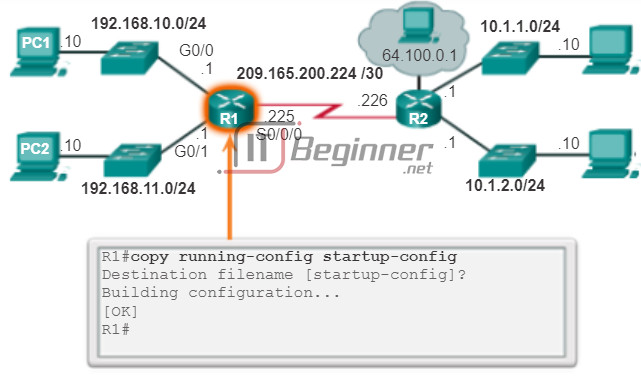 [/tab]
[tab]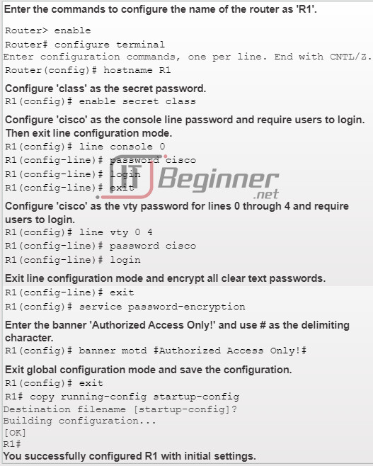 [/tab]
[/tabs]
6.4.1.2 Packet Tracer – Configure Initial Router Settings
In this activity, you will perform basic router configurations. You will secure access to the CLI and console port using encrypted and plain text passwords. You will also configure messages for users logging into the router. These banners also warn unauthorized users that access is prohibited. Finally, you will verify and save your running configuration.
Packet Tracer – Configure Initial Router Settings Instructions ./.
Packet Tracer – Configure Initial Router Settings – PKA ./.
6.4.2 Configure Interfaces
6.4.2.1 Configure LAN Interfaces
For routers to be reachable, router interfaces must be configured. Therefore, to enable a specific interface, enter interface configuration mode using the interface type-and-number global configuration mode command.
There are many different types of interfaces available on Cisco routers. In this example, the Cisco 1941 router is equipped with two Gigabit Ethernet interfaces and a serial WAN interface card (WIC) consisting of two interfaces; the interfaces are named as follows:
- Gigabit Ethernet 0/0 (G0/0)
- Gigabit Ethernet 0/1 (G0/1)
- Serial 0/0/0 (S0/0/0)
- Serial 0/0/1 (S0/0/1)
To enable a router interface, configure the following:
- IPv4 address and subnet mask – Configures the IP address and subnet mask using the ip address subnet-mask interface configuration command.
- Activate the interface – By default, LAN and WAN interfaces are not activated. The interface must be activated using the no shutdown command. This is similar to powering on the interface. The interface must also be connected to another device (a hub, a switch, or another router) for the physical layer to be active.
Although not required, it is good practice to configure a description on each interface to help document the network information. The description text is limited to 240 characters. On production networks, a description can be helpful in troubleshooting by providing information about the type of network that the interface is connected to and if there are any other routers on that network. If the interface connects to an ISP or service carrier, it is helpful to enter the third party connection and contact information.
Figure 1 shows the configuration of the LAN interfaces connected to R1. In Figure 2, practice configuring a LAN interface.
Note: Command abbreviations are used for the configuration of Gigabit Ethernet 0/1.
[tabs type=”horizontal”]
[tabs_head]
[tab_title]Figure 1[/tab_title]
[tab_title]Figure 2[/tab_title]
[/tabs_head]
[tab]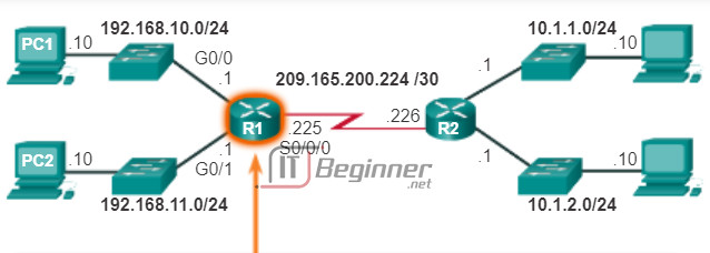
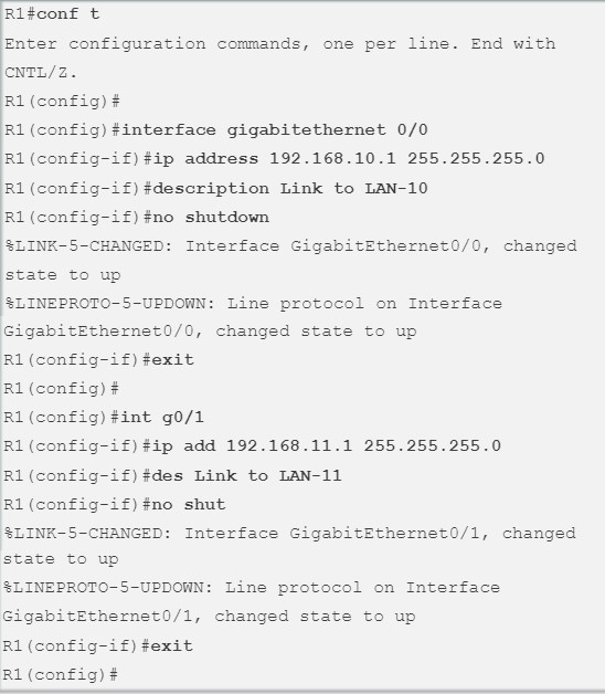 [/tab]
[tab]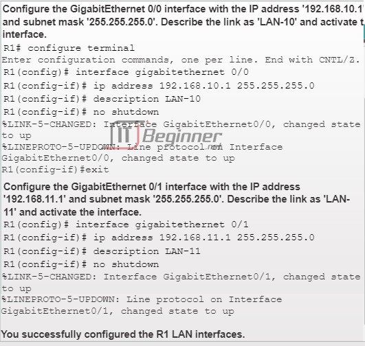 [/tab]
[/tabs]
6.4.2.2 Verify Interface Configuration
There are several commands that can be used to verify interface configuration. The most useful of these is the show ip interface brief command. The output generated displays all interfaces, their IP address, and their current status. The configured and connected interfaces should display a Status of “up” and Protocol of “up”. Anything else would indicate a problem with either the configuration or the cabling.
You can verify connectivity from the interface using the ping command. Cisco routers send five consecutive pings and measure minimal, average, and maximum round trip times. Exclamation marks verify connectivity.
Figure 1 displays the output of the show ip interface brief command, which reveals that the LAN interfaces and the WAN link are all activate and operational. Notice that the ping command generated five exclamation marks verifying connectivity to R2.
Other interface verification commands include:
- show ip route –Displays the contents of the IPv4 routing table stored in RAM.
- show interfaces –Displays statistics for all interfaces on the device.
- show ip interface –Displays the IPv4 statistics for all interfaces on a router.
Figure 2 displays the output of the show ip route command. Notice the three directly connected network entries and the local link interface entries.
Remember to save the configuration using the copy running-config startup-config command.
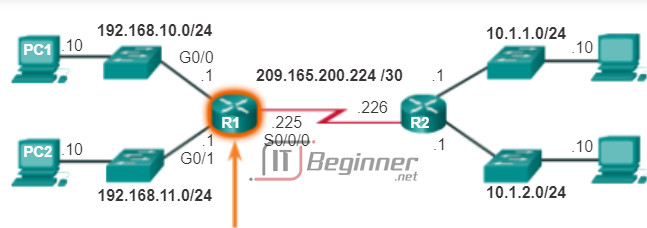
[tabs type=”horizontal”]
[tabs_head]
[tab_title]Figure 1[/tab_title]
[tab_title]Figure 2[/tab_title]
[/tabs_head]
[tab]
R1#show ip interface brief

Interface	        IP-Address	  OK?	Method	Status	Protocol
GigabitEthernet0/0	192.168.10.1	  YES	manual	up	up
GigabitEthernet0/1	192.168.11.1	  YES	manual	up	up
Serial0/0/0	        209.165.200.225   YES	manual	up	up
Serial0/0/1	        unassigned	  YES	NVRAM	administratively down	down
Vlan1	unassigned	YES	NVRAM 	administratively down	down
R1#
R1#ping 209.165.200.226

Type escape sequence to abort.
Sending 5, 100-byte ICMP Echos to 209.165.200.226, timeout is 2 seconds:
!!!!!
Success rate is 100 percent (5/5), round-trip min/avg/max = 1/2/9 ms

R1#
[/tab]
[tab]
R1#show ip route
Codes:	L - local, C - connected, S - static, R - RIP, M - mobile, B - BGP
 	D - EIGRP, EX - EIGRP external, O - OSPF, IA - OSPF inter area
 	N1 - OSPF NSSA external type 1, N2 - OSPF NSSA external type 2
 	E1 - OSPF external type 1, E2 - OSPF external type 2, E - EGP
 	i - IS-IS, L1 - IS-IS level-1, L2 - IS-IS level-2, ia - IS-IS inter area
 	* - candidate default, U - per-user static route, o - ODR
 	P - periodic downloaded static route
Gateway of last resort is not set
        10.0.0.0/8 is variably subnetted, 2 subnets, 2 masks
D	 	10.1.1.0/24 [90/2170112] via 209.165.200.226, 00:00:05, Serial0/0/0
D	 	10.1.2.0/24 [90/2170112] via 209.165.200.226, 00:00:05, Serial0/0/0
        192.168.10.0/24 is variably subnetted, 2 subnets, 3 masks
C	 	192.168.10.0/24 is directly connected, GigabitEthernet0/0
L	 	192.168.10.1/32 is directly connected, GigabitEthernet0/0
        192.168.11.0/24 is variably subnetted, 2 subnets, 3 masks
C	 	192.168.11.0/24 is directly connected, GigabitEthernet0/1
L	 	192.168.11.1/32 is directly connected, GigabitEthernet0/1
        209.165.200.0/24 is variably subnetted, 2 subnets, 3 masks
C	 	209.165.200.224/30 is directly connected, Serial0/0/0
L	 	209.165.200.225/32 is directly connected, Serial0/0/0
R1#
[/tab]
[/tabs]
6.4.3 Configuring the Default Gateway
6.4.3.1 Default Gateway on a Host
Most routers have, at a minimum, two interfaces. Each interface is configured with a separate IP address in a separate network.
For an end device to communicate over the network, it must be configured with the correct IP address information, including the default gateway address. The default gateway is only used when the host wants to send a packet to a device on another network. The default gateway address is generally the router interface address attached to the local network of the host. While it does not matter what address is actually configured on the router interface, the IP address of the host device and the router interface address must be in the same network.
The figures display a topology of a router with two separate interfaces. Each interface is connected to a separate network. G0/0 is connected to network 192.168.10.0, while G0/1 is connected to network 192.168.11.0. Each host device is configured with the appropriate default gateway address.
In Figure 1, PC1 sends a packet to PC2. In this example, the default gateway is not used; rather, PC1 addresses the packet with the IP address of PC2 and forwards the packet directly to PC2 through the switch.
In Figure 2, PC1 sends a packet to PC3. In this example, PC1 addresses the packet with the IP address of PC3, but then forwards the packet to the router. The router accepts the packet, accesses its route table to determine the appropriate exit interface based on the destination address, and then forwards the packet out of the appropriate interface to reach PC3.
[tabs type=”horizontal”]
[tabs_head]
[tab_title]Figure 1[/tab_title]
[tab_title]Figure 2[/tab_title]
[/tabs_head]
[tab]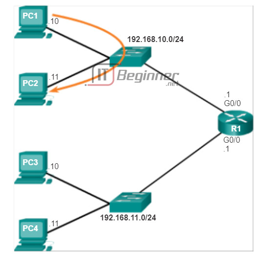 [/tab]
[tab]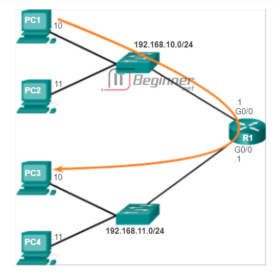 [/tab]
[/tabs]
6.4.3.2 Default Gateway on a Switch
A default gateway is used by all devices that require the use of a router to determine the best path to a remote destination. End devices require default gateway addresses, but so do intermediate devices, such as the Cisco IOS switch.
The IP address information on a switch is only necessary to manage the switch remotely. In other words, to be able to telnet to the switch, the switch must have an IP address to Telnet to. If the switch is only accessed from devices within the local network, only an IP address is required.
Configuring the IP address on a switch is done on the switch virtual interface (SVI):
S1(config)# interface vlan1
S1(config-vlan)# ip address 192.168.10.50 255.255.255.0
S1(config-vlan)# no shut
However, if the switch must be accessible by devices in a different network, the switch must be configured with a default gateway address, because packets that originate from the switch are handled just like packets that originate from a host device. Therefore, packets that originate from the switch and are destined for a device on the same network are forwarded directly to the appropriate device. Packets that originate from the switch and are destined for a device on a remote network must be forwarded to the default gateway for path determination.
To configure a default gateway on a switch use the following global configuration command:
S1(config)# ip default-gateway 192.168.10.1
Figure 1 shows an administrator connecting to a switch on a remote network. For the switch to forward response packets to the administrator, the default gateway must be configured.
A common misconception is that the switch uses its configured default gateway address to determine where to forward packets originating from hosts connected to the switch and destined for hosts on a remote network. Actually, the IP address and default gateway information is only used for packets that originate from the switch. Packets originating from hosts connected to the switch must already have default gateway information configured to communicate on remote networks. In Figure 2, practice configuring a default gateway on a switch.
[tabs type=”horizontal”]
[tabs_head]
[tab_title]Figure 1[/tab_title]
[tab_title]Figure 2[/tab_title]
[/tabs_head]
[tab]
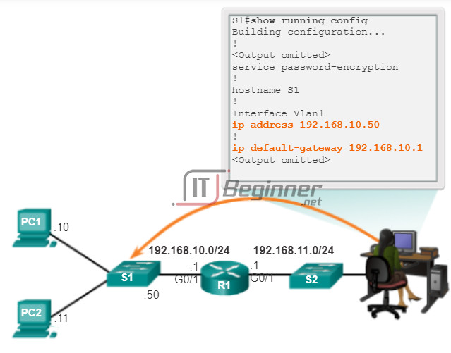
[/tab]
[tab]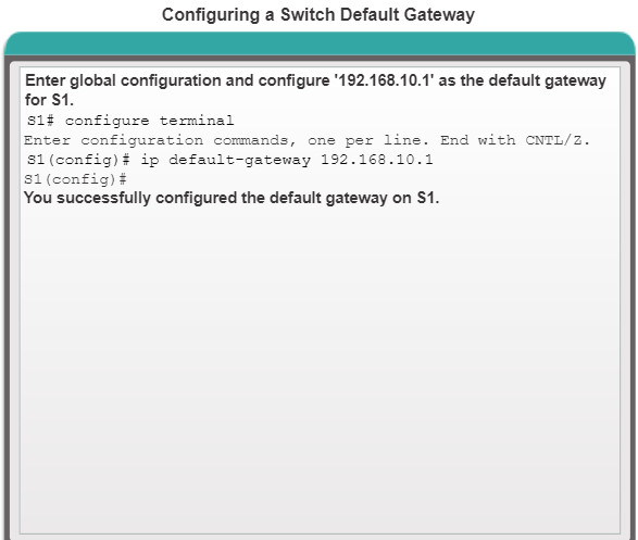 [/tab]
[/tabs]
6.4.3.3 Packet Tracer – Connect a Router to a LAN
In this activity, you will use various show commands to display the current state of the router. You will then use the Addressing Table to configure router Ethernet interfaces. Finally, you will use commands to verify and test your configurations.
Packet Tracer – Connect a Router to a LAN Instructions ./.
Packet Tracer – Connect a Router to a LAN – PKA ./.
6.4.3.4 Packet Tracer – Troubleshooting Default Gateway Issues
For a device to communicate across multiple networks, it must be configured with an IP address, subnet mask, and a default gateway. The default gateway is used when the host wants to send a packet to a device on another network. The default gateway address is generally the router interface address attached to the local network to which the host is connected. In this activity, you will finish documenting the network. You will then verify the network documentation by testing end-to-end connectivity and troubleshooting issues. The troubleshooting method you will use consists of the following steps:
- Verify the network documentation and use tests to isolate problems.
- Determine an appropriate solution for a given problem.
- Implement the solution.
- Test to verify the problem is resolved.
- Document the solution.
Packet Tracer – Troubleshooting Default Gateway Issues Instructions ./.
Packet Tracer – Troubleshooting Default Gateway Issues – PKA ./.
6.4.3.5 Lab – Initializing and Reloading a Router and Switch
In this lab, you will complete the following objectives:
- Part 1: Set Up the Topology and Initialize Devices
- Part 2: Configure Devices and Verify Connectivity
- Part 3: Display Device Information
Lab – Building a Switch and Router Network ./.
6.5 Summary
6.5.1 Summary
6.5.1.1 Class Activity – Can You Read This Map?
Note: It is suggested that students work in pairs; however, if preferred, students can complete this activity individually.
Your instructor will provide you with output generated by a router’s show ip route command. Use Packet Tracer to build a topology model using this routing information.
At a minimum, the following should be used in your topology model:
- 1 Catalyst 2960 switch
- 1 Cisco Series 1941 Router with one HWIC-4ESW switching port modular card and IOS version 15.1 or higher
- 3 PCs (can be servers, generic PCs, laptops, etc.)
Use the note tool in Packet Tracer to indicate the addresses of the router interfaces and possible addresses for the end devices you chose for your model. Label all end devices, ports, and addresses ascertained from the show ip route output/routing table information in your Packet Tracer file. Save your work in hard or soft copy to share with the class.
Class Activity – Can you read this map? Instructions ./.
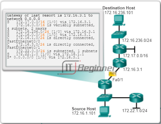
6.5.1.2 Packet Tracer – Skills Integration Challenge
Your network manager is impressed with your performance in your job as a LAN technician. She would like you to now demonstrate your ability to configure a router connecting two LANs. Your tasks include configuring basic settings on a router and a switch using the Cisco IOS. You will then verify your configurations, as well as configurations on existing devices by testing end-to-end connectivity.
Packet Tracer Skills Integration Challenge Instructions ./.
Packet Tracer Skills Integration Challenge – PKA ./.
6.5.1.3 Summary
The network layer, or OSI Layer 3, provides services to allow end devices to exchange data across the network. To accomplish this end-to-end transport, the network layer uses four basic processes: IP addressing for end devices, encapsulation, routing, and de-encapsulation.
The Internet is largely based on IPv4, which is still the most widely-used network layer protocol. An IPv4 packet contains the IP header and the payload. However, IPv4 has a limited number of unique public IP addresses available. This led to the development of IP version 6 (IPv6). The IPv6 simplified header offers several advantages over IPv4, including better routing efficiency, simplified extension headers, and capability for per-flow processing. Plus, IPv6 addresses are based on 128-bit hierarchical addressing as opposed to IPv4 with 32 bits. This dramatically increases the number of available IP addresses.
In addition to hierarchical addressing, the network layer is also responsible for routing.
Hosts require a local routing table to ensure that packets are directed to the correct destination network. The local table of a host typically contains the direct connection, the local network route and the local default route. The local default route is the route to the default gateway.
The default gateway is the IP address of a router interface connected to the local network. When a host needs to forward a packet to a destination address that is not on the same network as the host, the packet is sent to the default gateway for further processing.
When a router, such as the default gateway, receives a packet, it examines the destination IP address to determine the destination network. The routing table of a router stores information about directly-connected routes and remote routes to IP networks. If the router has an entry in its routing table for the destination network, the router forwards the packet. If no routing entry exists, the router may forward the packet to its own default route, if one is configured, or it will drop the packet.
Routing table entries can be configured manually on each router to provide static routing or the routers may communicate route information dynamically between each other using a routing protocol.
In order for routers to be reachable, the router interface must be configured. To enable a specific interface, enter interface configuration mode using the interface type-and-number global configuration mode command.