Introduction to Networks Instructor Materials – Chapter 2: Configuring a Network Operating System
2.0 Configuring a Network Operating System
2.0.1 Introduction
2.0.1.1 Introduction to Cisco IOS
Home networks typically interconnect a wide variety of end devices including PCs, laptops, tablets, smartphones, smart TVs, Digital Living Network Alliance (DLNA) compliant network media players, such as the Xbox 360 or PlayStation 3, and more.
All of these end devices are usually connected to a home router. Home routers are actually four devices in one:
- Router – Forwards data packets to and receives data packets from the Internet
- Switch – Connects end devices using network cables
- Wireless access point – Consists of a radio transmitter capable of connecting end devices wirelessly
- Firewall appliance – Secures outgoing traffic and restricts incoming traffic
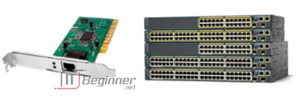
In larger, business networks with significantly more devices and traffic, these devices are often incorporated as independent, stand-alone devices, providing dedicated service. End-devices, such as PCs and laptops, are connected to network switches using wired connections. To send packets beyond the local network, network switches connect to network routers. Other infrastructure devices on a network include wireless access points and dedicated security devices, such as firewalls.
Each device is very different in hardware, use, and capability. But in all cases, it is the operating system that enables the hardware to function.
Operating systems are used on virtually all end user and network devices connected to the Internet. End user devices include devices such as smart phones, tablets, PCs, and laptops. Network devices, or intermediary devices, are devices used to transport data across the network and include switches, routers, wireless access points, and firewalls. The operating system on a network device is known as a network operating system.
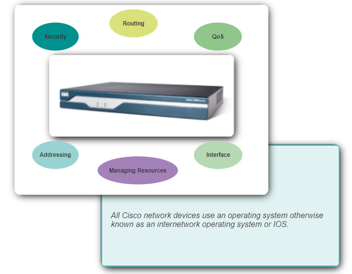
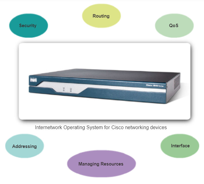
The Cisco Internetwork Operating System (IOS) is a generic term for the collection of network operating systems used on Cisco networking devices. Cisco IOS is used for most Cisco devices regardless of the type or size of the device.
This chapter will reference a basic network topology, consisting of two switches and two PCs, to demonstrate the use of Cisco IOS.
Upon completion of this chapter you will be able to:
- Explain the purpose of Cisco IOS.
- Explain how to access and navigate Cisco IOS to configure network devices.
- Describe the command structure of Cisco IOS software.
- Configure hostnames on a Cisco IOS device using the CLI.
- Use Cisco IOS commands to limit access to device configurations.
- Use Cisco IOS commands to save the running configuration.
- Explain how devices communicate across network media.
- Configure a host device with an IP address.
- Verify connectivity between two end devices.
2.0.1.2 Class Activity – It Is Just an Operating System
In this activity, imagine that you are employed as an engineer for a car manufacturing company. The company is currently working on a new car model. This model will have selected functions which can be controlled by the driver giving specific voice commands.
Design a set of commands used by this voice-activated control system, and to identify how they are going to be executed. The functions of the car that can be controlled by voice commands are:
- Lights
- Wipers
- Radio
- Telephone set
- Air conditioning
- Ignition
Class Activity – It Is Just an Operating System Instructions ./.
2.1 IOS Bootcamp
2.1.1 Cisco IOS
2.1.1.1 Operating Systems
All end devices and network devices connected to the Internet require an operating system (OS) to help them perform their function.
When a computer is powered on, it loads the OS, normally from a disk drive, into RAM. The portion of the OS code that interacts directly with the computer hardware is known as the kernel. The portion that interfaces with the applications and user is known as the shell. The user can interact with the shell using either the command-line interface (CLI) or graphical user interface (GUI).
When using the CLI, the user interacts directly with the system in a text-based environment by entering commands on the keyboard at a command prompt. The system executes the command, often providing textual output. The GUI interface allows the user to interact with the system in an environment that uses graphical images, multimedia, and text. Actions are performed by interacting with the images on screen. GUI is more user friendly and requires less knowledge of the command structure to utilize the system. For this reason, many individuals rely on the GUI environments. Many operating systems offer both GUI and CLI.
Click on the hardware, kernel, and shell portions of the figure for more information.
Most end device operating systems are accessed using a GUI, including MS Windows, MAC OS X, Linux, Apple iOS, Android, and more.
The operating system on home routers is usually called firmware. The most common method for configuring a home router is using a web browser to access an easy to use GUI. Most home routers enable the update of the firmware as new features or security vulnerabilities are discovered.
Infrastructure network devices use a network operating system. The network operating system used on Cisco devices is called the Cisco Internetwork Operating System (IOS). Cisco IOS is a generic term for the collection of network operating systems used on Cisco networking devices. Cisco IOS is used for most Cisco devices regardless of the type or size of the device. The most common method of accessing these devices is using a CLI.
This chapter will focus on a small business network switch topology. The topology consists of two switches and two PCs and will be used to demonstrate the use of Cisco IOS using the CLI.
[tabs type=”horizontal”]
[tabs_head]
[tab_title]Hardware[/tab_title]
[tab_title]Kernel[/tab_title]
[tab_title]Shell[/tab_title]
[/tabs_head]
[tab]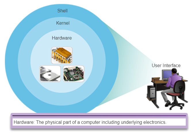 [/tab]
[tab]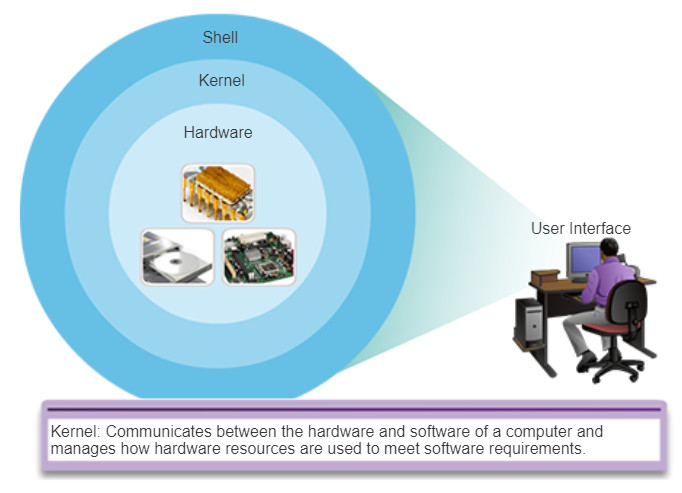 [/tab]
[tab]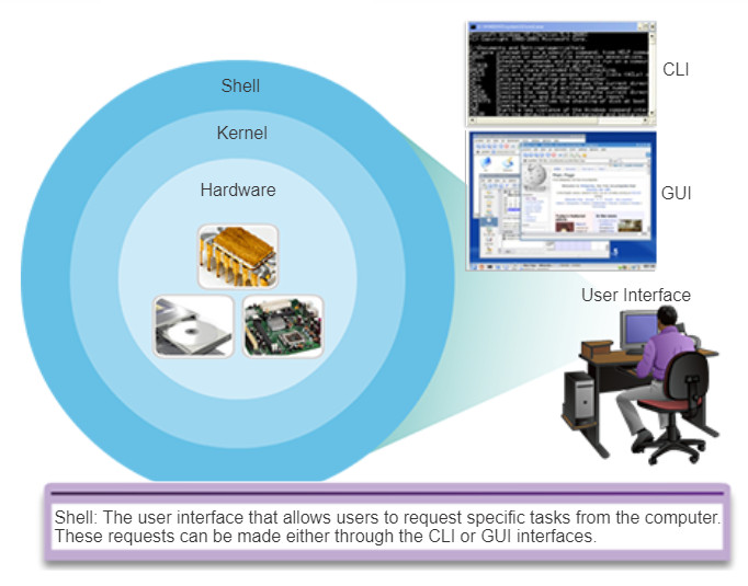 [/tab]
[/tabs]
2.1.1.2 Purpose of OS
Network operating systems are in many ways similar to the operating systems of PCs. An operating system performs a number of technical functions “behind the scenes” that enable a user to:
- Use a mouse
- View output on a monitor
- Enter text commands
- Select options within a dialog box window
The “behind the scenes” functions for switches and routers are very similar. The IOS on a switch or router provides the network technician with an interface. The technician can enter commands to configure, or program, the device to perform various networking functions. The IOS operational details vary on internetworking devices, depending on the purpose of the device and the features supported.
Cisco IOS is a term that encompasses a number of different operating systems that run on various networking devices. There are many distinct variations of Cisco IOS:
- IOS for switches, routers, and other Cisco networking devices
- IOS numbered versions for a given Cisco networking device
- IOS feature sets providing distinct packages of features and services
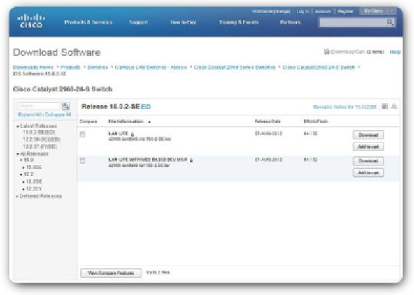
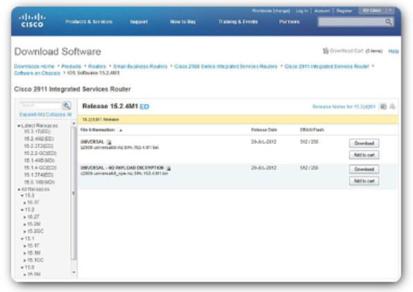
Just as a PC may be running Microsoft Windows 8 and a MacBook may be running OS X, a Cisco networking device runs a particular version of the Cisco IOS. The version of IOS is dependent on the type of device being used and the required features. While all devices come with a default IOS and feature set, it is possible to upgrade the IOS version or feature set, in order to obtain additional capabilities.
In this course, you will focus primarily on Cisco IOS Release 15.x. Figure 1 displays a list of IOS software releases for a Cisco Catalyst 2960 Switch. Figure 2 displays a list of IOS software releases for a Cisco 2911 Integrated Services Router (ISR).
2.1.1.3 Location of the Cisco IOS
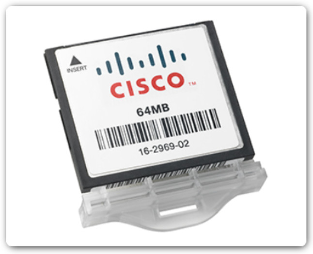
The IOS file itself is several megabytes in size and is stored in a semi-permanent memory area called flash. The figure shows a compact flash card. Flash memory provides non-volatile storage. This means that the contents of the memory are not lost when the device loses power. Although the contents of flash are not lost during a loss of power, they can be changed or overwritten if needed. This allows the IOS to be upgraded to a newer version or to have new features added without replacing hardware. Additionally, flash can be used to store multiple versions of IOS software at the same time.
In many Cisco devices, the IOS is copied from flash into random access memory (RAM) when the device is powered on. The IOS then runs from RAM when the device is operating. RAM has many functions including storing data that is used by the device to support network operations. Running the IOS in RAM increases performance of the device, however, RAM is considered volatile memory because data is lost during a power cycle. A power cycle is when a device is purposely or accidently powered off and then powered back on.
The quantity of flash memory and RAM memory required for a given IOS varies dramatically. For the purposes of network maintenance and planning, it is important to determine the flash and RAM requirements for each device, including the maximum flash and RAM configurations. It is possible that the requirements of the newest versions of IOS could demand more RAM and flash than can be installed on some devices.
2.1.1.4 IOS Functions
Cisco IOS routers and switches perform functions that network professionals depend upon to make their networks operate as expected. Major functions performed or enabled by Cisco routers and switches include:
- Providing network security
- IP addressing of virtual and physical interfaces
- Enabling interface-specific configurations to optimize connectivity of the respective media
- Routing
- Enabling quality of service (QoS) technologies
- Supporting network management technologies
Each feature or service has an associated collection of configuration commands that allow a network technician to implement it.
The services provided by the Cisco IOS are generally accessed using a CLI.
2.1.1.5 Video Demonstration – CCO Accounts and IOS Image Exploration
This video introduces Cisco Connection Online (CCO). CCO has a wealth of information available regarding Cisco products and services.
2.1.2 Accessing a Cisco IOS Device
2.1.2.1 Console Access Method
There are several ways to access the CLI environment. The most common methods are:
- Console
- Telnet or SSH
- AUX port
Console
The console port is a management port that provides out-of-band access to Cisco device. Out-of-band access refers to access via a dedicated management channel that is used for device maintenance purposes only. The advantage of using a console port is that the device is accessible even if no networking services have been configured, such as when performing an initial configuration of the networking device. When performing an initial configuration, a computer running terminal emulation software is connected to the console port of the device using a special cable. Configuration commands for setting up the switch or router can be entered on the connected computer.
The console port can also be used when the networking services have failed and remote access of the Cisco IOS device is not possible. If this occurs, a connection to the console can enable a computer to determine the status of the device. By default, the console conveys the device startup, debugging, and error messages. After the network technician is connected to the device, the network technician can perform any configuration commands necessary using the console session.
For many IOS devices, console access does not require any form of security, by default. However, the console should be configured with passwords to prevent unauthorized device access. In the event that a password is lost, there is a special set of procedures for bypassing the password and accessing the device. The device should also be located in a locked room or equipment rack to prevent unauthorized physical access.
2.1.2.2 Telnet, SSH, and AUX Access Methods
Telnet
Telnet is a method for remotely establishing a CLI session of a device, through a virtual interface, over a network. Unlike the console connection, Telnet sessions require active networking services on the device. The network device must have at least one active interface configured with an Internet address, such as an IPv4 address. Cisco IOS devices include a Telnet server process that allows users to enter configuration commands from a Telnet client. In addition to supporting the Telnet server process, the Cisco IOS device also contains a Telnet client. This allows a network administrator to telnet from the Cisco device CLI to any other device that supports a Telnet server process.
SSH
The Secure Shell (SSH) protocol provides a remote login similar to Telnet, except that it uses more secure network services. SSH provides stronger password authentication than Telnet and uses encryption when transporting session data. This keeps the user ID, password, and the details of the management session private. As a best practice, use SSH instead of Telnet whenever possible.
Most versions of Cisco IOS include an SSH server. In some devices, this service is enabled by default. Other devices require the SSH server to be enabled manually. IOS devices also include an SSH client that can be used to establish SSH sessions with other devices.
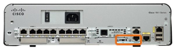
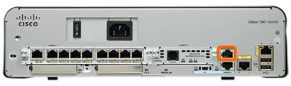
AUX
An older way to establish a CLI session remotely is via a telephone dialup connection using a modem connected to the auxiliary (AUX) port of a router, which is highlighted in the figure. Similar to the console connection, the AUX method is also an out-of-band connection and does not require any networking services to be configured or available on the device. In the event that network services have failed, it may be possible for a remote administrator to access the switch or router over a telephone line.
The AUX port can also be used locally, like the console port, with a direct connection to a computer running a terminal emulation program. However, the console port is preferred over the AUX port for troubleshooting because it displays startup, debugging, and error messages by default.
Note: Cisco Catalyst switches do not support an auxiliary connection.
2.1.2.3 Terminal Emulation Programs
There are a number of excellent terminal emulation programs available for connecting to a networking device either by a serial connection over a console port or by a Telnet/SSH connection. Some of these include:
- PuTTY (Figure 1)
- Tera Term (Figure 2)
- SecureCRT (Figure 3)
- HyperTerminal
- OS X Terminal
These programs allow you to enhance your productivity by adjusting window sizes, changing font sizes, and changing color schemes.
[tabs type=”horizontal”]
[tabs_head]
[tab_title]PuTTY[/tab_title]
[tab_title]Tera Term[/tab_title]
[tab_title]SecureCRT[/tab_title]
[/tabs_head]
[tab]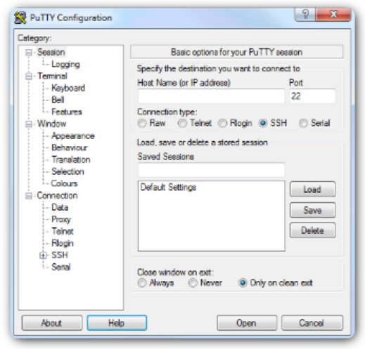 [/tab]
[tab]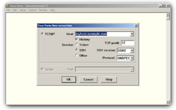 [/tab]
[tab]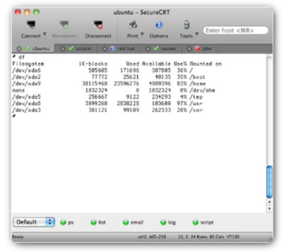 [/tab]
[/tabs]
2.1.2.4 Activity – Accessing Devices
2.1.3 Navigating the IOS
2.1.3.1 Cisco IOS Modes of Operation
After a network technician is connected to a device, it is possible to configure it. The network technician must navigate through various modes of the IOS. The Cisco IOS modes are quite similar for switches and routers. The CLI uses a hierarchical structure for the modes.
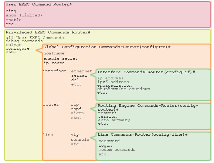
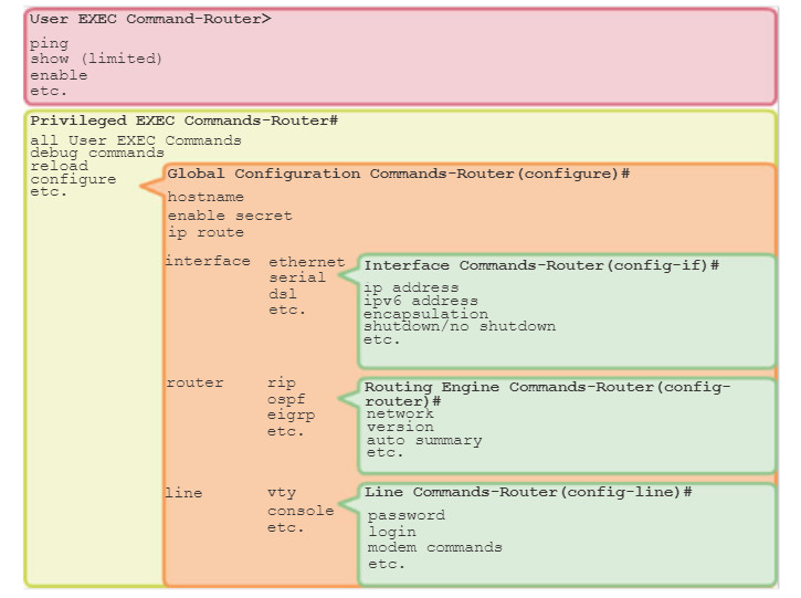
In hierarchical order from most basic to most specialized, the major modes are:
- User executive (User EXEC) mode
- Privileged executive (Privileged EXEC) mode
- Global configuration mode
- Other specific configuration modes, such as interface configuration mode
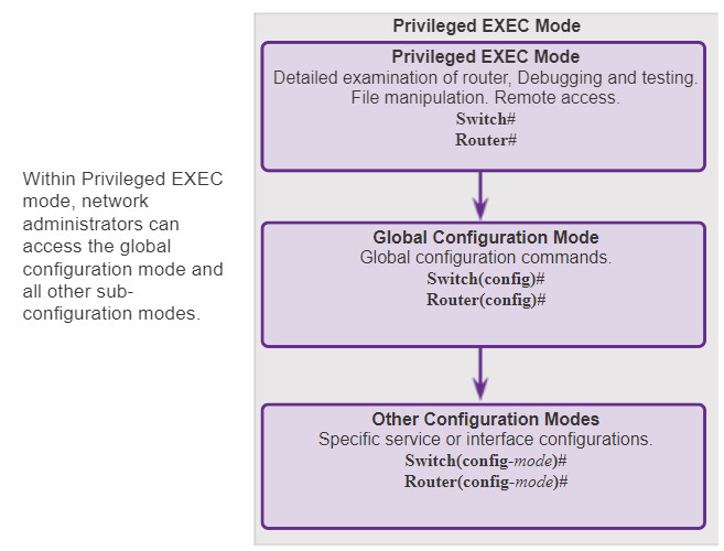
Each mode has a distinctive prompt and is used to accomplish particular tasks with a specific set of commands that are available only to that mode. For example, global configuration mode allows a technician to configure settings on the device that affects the device as a whole, such as configuring a name for the device. However, a different mode is required if the network technician wants to configure security settings on a specific port on a switch, for example. In this case, the network technician must enter interface configuration mode for that specific port. All configurations that are entered in interface configuration mode apply only to that port.
The hierarchical structure can be configured to provide security. Different authentication can be required for each hierarchical mode. This controls the level of access that network personnel can be granted.
The figure shows the IOS mode structure with typical prompts and features.
2.1.3.2 Primary Modes
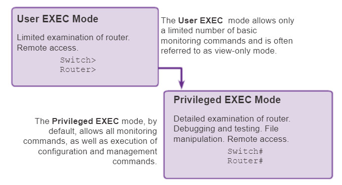
The two primary modes of operation are user EXEC mode and privileged EXEC mode. As a security feature, the Cisco IOS software separates the EXEC sessions into two levels of access. As shown in the figure, the privileged EXEC mode has a higher level of authority in what it allows the user to do with the device.
User EXEC Mode
The user EXEC mode has limited capabilities but is useful for some basic operations. The user EXEC mode is at the most basic level of the modal hierarchical structure. This mode is the first mode encountered upon entrance into the CLI of an IOS device.
The user EXEC mode allows only a limited number of basic monitoring commands. This is often referred to as view-only mode. The user EXEC level does not allow the execution of any commands that might change the configuration of the device.
By default, there is no authentication required to access the user EXEC mode from the console. However, it is a good practice to ensure that authentication is configured during the initial configuration.
The user EXEC mode is identified by the CLI prompt that ends with the > symbol. This is an example that shows the > symbol in the prompt:
Switch>
Privileged EXEC Mode
The execution of configuration and management commands requires that the network administrator use the privileged EXEC mode or a more specific mode in the hierarchy. This means that a user must enter user EXEC mode first, and from there, access privileged EXEC mode.
The privileged EXEC mode can be identified by the prompt ending with the # symbol.
Switch#
By default, privileged EXEC mode does not require authentication. It is a good practice to ensure that authentication is configured.
Global configuration mode and all other more specific configuration modes can only be reached from the privileged EXEC mode. In a later section of this chapter, we will examine device configuration and some of the configuration modes.
2.1.3.3 Global Configuration Mode and Submodes
Global configuration mode and interface configuration modes can only be reached from the privileged EXEC mode.
Global Configuration Mode
The primary configuration mode is called global configuration or global config. From global configuration mode, CLI configuration changes are made that affect the operation of the device as a whole. The global configuration mode is accessed before accessing specific configuration modes.
The following CLI command is used to take the device from privileged EXEC mode to the global configuration mode and to allow entry of configuration commands from a terminal:
Switch# configure terminal
After the command is executed, the prompt changes to show that the switch is in global configuration mode.
Switch(config)#
Specific Configuration Modes
From the global configuration mode, the user can enter different sub-configuration modes. Each of these modes allows the configuration of a particular part or function of the IOS device. The list below shows a few of them:
- Interface mode – to configure one of the network interfaces (Fa0/0, S0/0/0)
- Line mode – to configure one of the physical or virtual lines (console, AUX, VTY)
Figure 1 shows the prompts for some of these modes. To exit a specific configuration mode and return to global configuration mode, enter exit at a prompt. To leave configuration mode completely and return to privileged EXEC mode, enter end or use the key sequence Ctrl-Z.
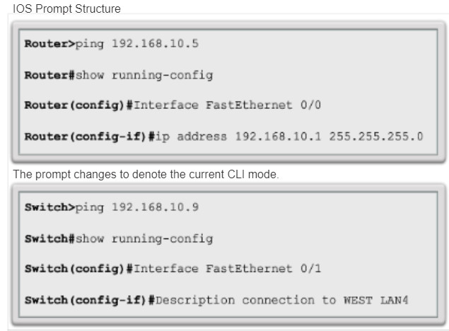
Command Prompts
When using the CLI, the mode is identified by the command-line prompt that is unique to that mode. By default, every prompt begins with the device name. Following the name, the remainder of the prompt indicates the mode. For example, the default prompt for the global configuration mode on a switch would be:
Switch(config)#
As commands are used and modes are changed, the prompt changes to reflect the current context as shown in Figure 2.
2.1.3.4 Navigating between IOS Modes
Moving Between the User EXEC and Privileged EXEC Modes
The enable and disable commands are used to change the CLI between the user EXEC mode and the privileged EXEC mode, respectively.
In order to access the privileged EXEC mode, use the enable command. The privileged EXEC mode is sometimes called the enable mode.
The syntax for entering the enable command is:
Switch> enable
This command is executed without the need for an argument or keyword. After the Enter key is pressed, the prompt changes to:
Switch#
The # at the end of the prompt indicates that the switch is now in privileged EXEC mode.
If password authentication is configured for the privileged EXEC mode, the IOS prompts for the password.
For example:
Switch> enable
Password:
Switch#
The disable command is used to return from the privileged EXEC to the user EXEC mode.
For example:
Switch# disable
Switch>
As the figure shows, the commands for accessing the privileged EXEC mode and for returning to the user EXEC mode on a Cisco router are identical to those used on a Cisco switch.
[tabs type=”horizontal”]
[tabs_head]
[tab_title]Router[/tab_title]
[tab_title]Switch[/tab_title]
[/tabs_head]
[tab]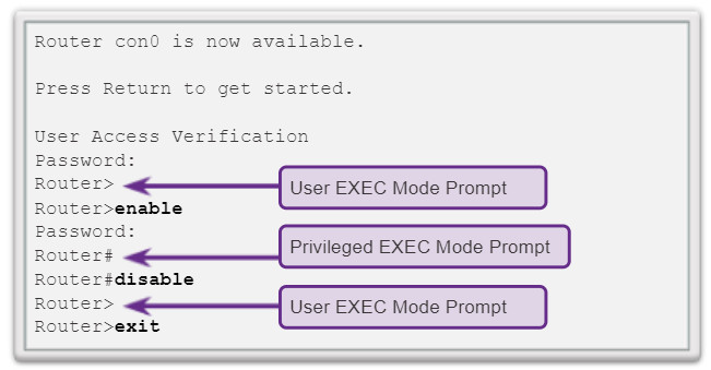 [/tab]
[tab]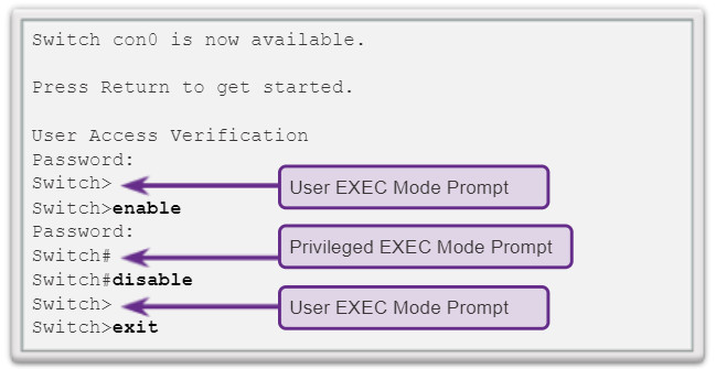 [/tab]
[/tabs]
2.1.3.5 Navigating between IOS Modes (Cont.)
Moving from and to Global Configuration Mode and Submodes
To quit from the global configuration mode and return to the privileged EXEC mode, enter the exit command.
Note that entering the exit command in privileged EXEC mode causes the console session to be ended. That is, upon entering exit in privileged EXEC mode, you will be presented with the screen that you see when you first initiate a console session. At this screen you have to press the Enter key to enter user EXEC mode.
To move from any submode of the global configuration mode to the mode one step above it in the hierarchy of modes, enter the exit command. Figure 1 illustrates moving from user EXEC mode to privileged EXEC mode, then entering global configuration mode, interface configuration mode, back to global configuration mode and back again to privileged EXEC mode using the exit command.
To move from any submode of the privileged EXEC mode to the privileged EXEC mode, enter the end command or enter the key combination Ctrl+Z. Figure 2 illustrates moving from VLAN configuration mode all the way back to privileged EXEC mode using the end command.
To move from any submode of the global configuration mode to another “immediate” submode of the global configuration mode, simply enter the corresponding command that is normally entered from global configuration mode. Figure 3 illustrates moving from the line configuration mode, Switch(config-line)#, to the interface configuration mode, Switch(config-if)#, without having to exit line configuration mode.
[tabs type=”horizontal”]
[tabs_head]
[tab_title]1[/tab_title]
[tab_title]2[/tab_title]
[tab_title]3[/tab_title]
[/tabs_head]
[tab]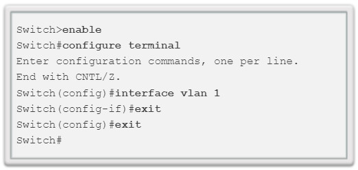 [/tab]
[tab]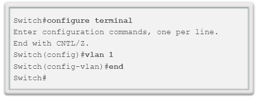 [/tab]
[tab]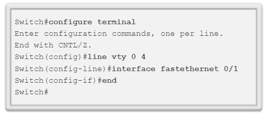 [/tab]
[/tabs]
2.1.3.6 Video Demonstration – Navigating the IOS
2.1.4 The Command Structure
2.1.4.1 IOS Command Structure
Basic IOS Command Structure
A Cisco IOS device supports many commands. Each IOS command has a specific format or syntax and can only be executed at the appropriate mode. The general syntax for a command is the command followed by any appropriate keywords and arguments. Some commands include a subset of keywords and arguments that provide additional functionality. Commands are used to execute an action, and the keywords are used to identify where or how to execute the command.
As shown in Figure 1, the command is the initial word or words entered in the command line following the prompt. The commands are not case-sensitive. Following the command are one or more keywords and arguments. After entering each complete command, including any keywords and arguments, press the Enter key to submit the command to the command interpreter.
The keywords describe specific parameters to the command interpreter. For example, the show command is used to display information about the device. This command has various keywords that must be used to define what particular output should be displayed. For example:
Switch# show running-config
The command show is followed by the keyword running-config. The keyword specifies that the running configuration is to be displayed as the output.
IOS Command Conventions
A command might require one or more arguments. Unlike a keyword, an argument is generally not a predefined word. An argument is a value or variable defined by the user. To determine the keywords and arguments required for a command, refer to the command syntax. The syntax provides the pattern or format that must be used when entering a command.
For instance the syntax for using the description command is:
Switch(config-if)# description string
As shown in Figure 2, boldface text indicates commands and keywords that are typed as shown and italic text indicates an argument for which you supply the value. For the description command, the argument is a string value. The string value can be any text string of up to 80 characters.
Therefore, when applying a description to an interface with the description command, enter a line such as this:
Switch(config-if)# description MainHQ Office Switch
The command is description and the user defined argument is MainHQ Office Switch.
The following examples demonstrate some conventions used to document and use IOS commands.
For the ping command:
Syntax:
Switch> ping IP-address
Example with values:
Switch> ping 10.10.10.5
The command is ping and the user defined argument is the 10.10.10.5.
Similarly, the syntax for entering the traceroute command is:
Syntax:
Switch> traceroute IP-address
Example with values:
Switch> traceroute 192.168.254.254
The command is traceroute and the user defined argument is the 192.168.254.254.
[tabs type=”horizontal”]
[tabs_head]
[tab_title]Basic IOS Command Structure[/tab_title]
[tab_title]IOS Command Conventions[/tab_title]
[/tabs_head]
[tab]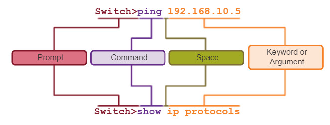 [/tab]
[tab]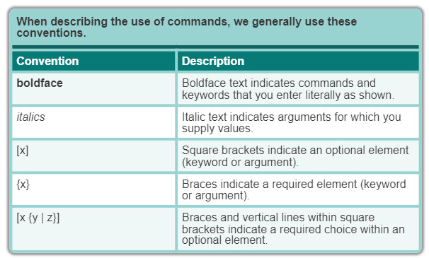 [/tab]
[/tabs]
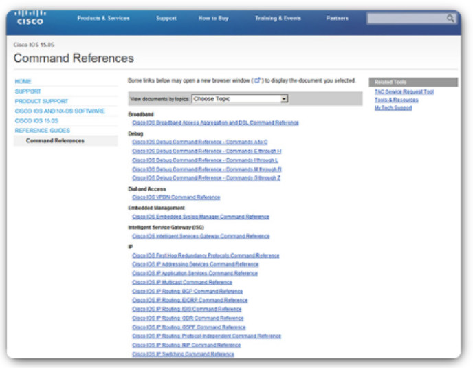
2.1.4.2 Cisco IOS Command Reference
The Cisco IOS Command Reference is a collection of online documentation which describes in detail the IOS commands used on Cisco devices. The Command Reference is the ultimate source of information for a particular IOS command, similar to how a dictionary is the ultimate source for information about a particular word.
The Command Reference is a fundamental resource that network engineers use to check various characteristics of a given IOS command. Some of the more common characteristics are:
- Syntax – the most detailed version of the syntax for a command that can be found
- Default – the manner in which the command is implemented on a device with a default configuration
- Mode – the configuration mode on the device where the command is entered
- History – descriptions of how the command is implemented relative to the IOS version
- Usage Guidelines – guidelines describing specifically how to implement the command
- Examples – useful examples that illustrate common scenarios that use the command
To navigate to the Command Reference and find a particular command follow the steps below:
- Step 1. Go to www.cisco.com.
- Step 2. Click Support.
- Step 3. Click Networking Software (IOS & NX-OS).
- Step 4. Click 15.2M&T (for example).
- Step 5. Click Reference Guides.
- Step 6. Click CommandReferences.
- Step 7. Click the particular technology that encompasses the command you are referencing.
- Step 8. Click the link on the left that alphabetically matches the command you are referencing.
- Step 9. Click the link for the command.
For example, the description command is found under the Cisco IOS Interface and Hardware Component Command Reference, under the link for the alphabetic range D through E.
Note: Complete PDF versions of the command references for a particular technology can be downloaded from links on the page that you reach after completing Step 7 above.
2.1.4.3 Context-Sensitive Help
The IOS has several forms of help available:
- Context-Sensitive Help
- Command Syntax Check
- Hot Keys and Shortcuts
Context-Sensitive Help
The context-sensitive help provides a list of commands and the arguments associated with those commands within the context of the current mode. To access context-sensitive help, enter a question mark, ?, at any prompt. There is an immediate response without the need to use the Enter key.
One use of context-sensitive help is to get a list of available commands. This can be used when you are unsure of the name for a command or you want to see if the IOS supports a particular command in a particular mode.
For example, to list the commands available at the user EXEC level, enter a question mark, ?, at the Switch> prompt.
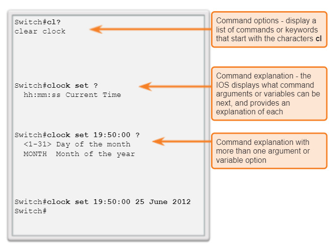
Another use of context-sensitive help is to display a list of commands or keywords that start with a specific character or characters. After entering a character sequence, if a question mark is immediately entered, without a space, the IOS will display a list of commands or keywords for this context that start with the characters that were entered.
For example, enter sh? to get a list of commands that begins with the character sequence sh.
A final type of context-sensitive help is used to determine which options, keywords, or arguments are matched with a specific command. When entering a command, enter a space followed by a ? to determine what can or should be entered next.
As shown in the figure, after typing the command clock set 19:50:00, we can enter the ? to determine the additional options or keywords available for this command.
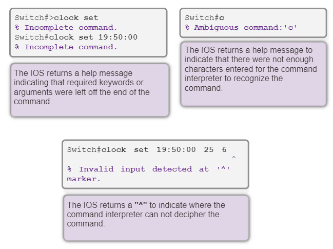
2.1.4.4 Command Syntax Check
When a command is submitted by pressing the Enter key, the command line interpreter parses the command from left to right to determine what action is being requested. The IOS generally only provides negative feedback, as shown in Figure 1. If the interpreter understands the command, the requested action is executed and the CLI returns to the appropriate prompt. However, if the interpreter cannot understand the command being entered, it will provide feedback describing what is wrong with the command.
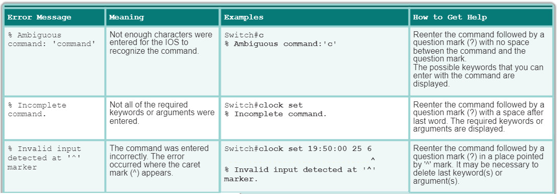
Figure 2 shows three different types of error messages:
- Ambiguous command
- Incomplete command
- Incorrect command
The clock set command is an ideal IOS command for experimenting with the various command syntax check help messages as shown in Figure 1. Figure 2 provides help for the three types of error messages.
2.1.4.5 Hot Keys and Shortcuts
The IOS CLI provides hot keys and shortcuts that make configuring, monitoring, and troubleshooting easier.
The figure shows most of the shortcuts. The following are worthy of special note:
- Down Arrow – Allows the user to scroll forward through former commands
- Up Arrow – Allows the user to scroll backward through former commands
- Tab – Completes the remainder of a partially typed command or keyword
- Ctrl-A – Moves to the beginning of the line
- Ctrl-E – Moves to the end of the line
- Ctrl-R – Redisplays a line
- Ctrl-Z – Exits the configuration mode and returns to user EXEC
- Ctrl-C – Exits the configuration mode or aborts the current command
- Ctrl-Shift-6 – Allows the user to interrupt an IOS process such as ping or traceroute
Examining some of these in more detail:
Tab
Tab complete is used to complete the remainder of abbreviated commands and parameters if the abbreviation contains enough letters to be different from any other currently available commands or parameters. When enough of the command or keyword has been entered to appear unique, press the Tab key and the CLI will display the rest of the command or keyword.
This is a good technique to use when you are learning because it allows you to see the full word used for the command or keyword.
Ctrl-R
Redisplay the line will refresh the line just typed. Use Ctrl-R to redisplay the line. For example, you may find that the IOS is returning a message to the CLI just as you are typing a line. You can use Ctrl-R to refresh the line and avoid having to retype it.
In this example, a message regarding a failed interface is returned in the middle of a command.
Switch# show mac-
16w4d: %LINK-5-CHANGED: Interface FastEthernet0/10, changed state to down
16w4d: %LINEPROTO-5-UPDOWN: Line protocol on Interface FastEthernet0/10, changed state to down
To redisplay to line that you were typing use Ctrl-R:
Switch# show mac
Ctrl-Z
Exit configuration mode will leave any configuration mode and return to privileged EXEC mode. Because the IOS has a hierarchical mode structure, you may find yourself several levels down. Rather than exit each mode individually, use Ctrl-Z to return directly to the privileged EXEC prompt at the top level.
Up and Down Arrows
Previous command keys will recall the history of commands entered. The Cisco IOS software buffers several past commands and characters so that entries can be recalled. The buffer is useful for re-entering commands without retyping.
Key sequences are available to scroll through these buffered commands. Use the Up Arrow key (Ctrl-P) to display the previously entered commands. Each time this key is pressed, the next successively older command will be displayed. Use the Down Arrow key (Ctrl-N) to scroll forward through the history to display the more recent commands.
Ctrl-Shift-6
The escape sequence will interrupt any running process. When an IOS process is initiated from the CLI, such as a ping or traceroute, the command runs until it is complete or is interrupted. While the process is running, the CLI is unresponsive. To interrupt the output and interact with the CLI, press Ctrl-Shift-6.
Ctrl-C
This interrupts the entry of a command and exits the configuration mode. This is useful after entering a command that needs to be cancelled.
Abbreviated commands or keywords
Commands and keywords can be abbreviated to the minimum number of characters that identify a unique selection. For example, the configure command can be abbreviated to conf because configure is the only command that begins with conf. An abbreviation of con will not work because more than one command begins with con.
Keywords can also be abbreviated.
As another example, show interfaces can be abbreviated like this:
Switch# show interfaces
Switch# show int
You can abbreviate both the command and the keywords, for example:
Switch# sh int
| CLI Line Editing | |
|---|---|
| Tab | Completes a partial command name entry. |
| Backspace | Erases the character to the left of the cursor. |
| Ctrl-D | Erases the character at the cursor. |
| Ctrl-K | Erases all characters from the cursor to the end of the command line. |
| Esc D | Erases all characters from the cursor to the end of the word. |
| Ctrl-U or Ctrl-X | Erases all characters from the cursor back to the beginning of the command line. |
| Ctrl-W | Erases the word to the left of the cursor. |
| Ctrl-A | Moves the cursor to the beginning of the line. |
| Left Arrow or Ctrl-B | Moves the cursor one character to the left. |
| Esc B | Moves the cursor back one word to the left. |
| Esc F | Moves the cursor forward one word to the right. |
| Right Arrow or Ctrl-F | Moves the cursor one character to the right. |
| Ctrl-E | Moves the cursor to the end of command line. |
| Up Arrow or Ctrl-P | Recalls command in the history buffer, beginning with the most recent commands. |
| Ctrl-R or Ctrl-I or Ctrl-L | Redisplays the system prompt and command line after a console message is received. |
NOTE: “Delete“, the key to erase to the right of the cursor, is not recognized by terminal emulation programs.)
| At the “—–More—–” prompt | |
|---|---|
| Enter Key | Displays the next line. |
| Space Bar | Displays the next screen. |
| Any Key | Ends the display string, returning to privileged EXEC mode. |
| Break Keys | |
|---|---|
| Ctrl-C | When in any configuration mode, ends the configuration mode and returns to privileged EXEC mode. When in setup mode, aborts back to the command prompt. |
| Ctrl-Z | When in any configuration mode, ends the configuration mode and returns to privileged EXEC mode. |
| Ctrl-Shift-6 | All-purpose break sequence. Use to abort DNS lookups, traceroutes, pings. |
NOTE: Control keys – Press and hold the key and then press the specified letter key.
Escape sequences – Press and release the key, and then press the letter key.
2.1.4.6 IOS Examination Commands
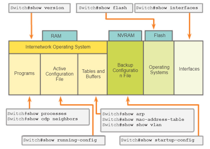
In order to verify and troubleshoot network operation, we must examine the operation of the devices. The basic examination command is the show command.
There are many different variations of this command. As you develop more skill with the IOS, you will learn to use and interpret the output of the show commands. Use the show ? command to get a list of available commands in a given context, or mode.
A typical show command can provide information about the configuration, operation, and status of parts of a Cisco switch or router. The figure highlights some of the common IOS commands.
In this course, we focus on mostly basic show commands.
A very commonly used show command is show interfaces. This command displays statistics for all interfaces on the device. To view the statistics for a specific interface, enter the show interfaces command followed by the specific interface type and slot/port number. For example:
Switch# show interfaces fastethernet 0/1
Some other show commands frequently used by network technicians include:
show startup-config – Displays the saved configuration located in NVRAM.
show running-config – Displays the contents of the currently running configuration file.
The More Prompt
When a command returns more output than can be displayed on a single screen, the –More– prompt appears at the bottom of the screen. When a –More– prompt appears, press the Space bar to view the next portion of output. To display only the next line, press the Enter key. If any other key is pressed, the output is cancelled and you are returned to the prompt.
2.1.4.7 The show version Command
One of the most commonly used commands on a switch or router is:
Switch# show version
This command displays information about the currently loaded IOS version, along with hardware and device information. If you are logged into a router or switch remotely, the show version command is an excellent means of quickly finding useful summary information about the particular device to which you are connected. Some of the information points shown from this command are:
- Software version – IOS software version (stored in flash)
- Bootstrap version – Bootstrap version (stored in Boot ROM)
- System up-time – Time since last reboot
- System restart info – Method of restart (e.g., power cycle, crash)
- Software image name – IOS filename stored in flash
- Router type and processor type – Model number and processor type
- Memory type and allocation (shared/main) – Main Processor RAM and Shared Packet I/O buffering
- Software features – Supported protocols/feature sets
- Hardware interfaces – Interfaces available on the device
- Configuration register – Sets bootup specifications, console speed setting, and related parameters
Figure 1 displays the output for a Cisco 1941 ISR, while Figure 2 displays the output for a Cisco 2960 Catalyst switch.
Router#show version
Cisco IOS Software, C1900 Software (C1900-UNIVERSALK9-M), Version 15.2(4)M1, RELEASE SOFTWARE (fc1)
Technical Support: http://www.cisco.com/techsupport
Copyright (c) 1986-2012 by Cisco Systems, Inc.
Compiled Thu 26-Jul-12 19:34 by prod_rel_team

ROM: System Bootstrap, Version 15.0(1r)M15, RELEASE SOFTWARE (fc1)

cisco1941 uptime is 41 minutes
System returned to ROM by power-on
System image file is ""flash0:c1900-universalk9-mz.SPA.152-4.M1.bin""
Last reload type: Normal Reload
Last reload reason: power-on

This product contains cryptographic features and is subject to United
States and local country laws governing import, export, transfer and
use. Delivery of Cisco cryptographic products does not imply
third-party authority to import, export, distribute or use encryption.
Importers, exporters, distributors and users are responsible for
compliance with U.S. and local country laws. By using this product you agree to comply with applicable laws and regulations. If you are unable
--More--
Switch#show version
Cisco IOS Software, C2960 Software (C2960-LANBASEK9-M), Version 15.0(2)SE, RELEASE SOFTWARE (fc1)
Technical Support: http://www.cisco.com/techsupport
Copyright (c) 1986-2012 by Cisco Systems, Inc.
Compiled Sat 28-Jul-12 00:29 by prod_rel_team

ROM: Bootstrap program is C2960 boot loader
BOOTLDR: C2960 Boot Loader (C2960-HBOOT-M) Version 12.2(53r)SEY3, RELEASE SOFTWARE (fc1)

Switch uptime is 44 minutes
System returned to ROM by power-on
System image file is ""flash:/c2960-lanbasek9-mz.150-2.SE.bin""

This product contains cryptographic features and is subject to United
States and local country laws governing import, export, transfer and
use. Delivery of Cisco cryptographic products does not imply
third-party authority to import, export, distribute or use encryption.
Importers, exporters, distributors and users are responsible for
compliance with U.S. and local country laws. By using this product you
agree to comply with applicable laws and regulations. If you are unable
to comply with U.S. and local laws, return this product immediately.

--More--
2.1.4.8 Packet Tracer – Navigating the IOS
In this activity, you will practice skills necessary for navigating the Cisco IOS, including different user access modes, various configuration modes, and common commands you use on a regular basis. You also practice accessing the context-sensitive help by configuring the clock command.
Packet Tracer – Navigating the IOS Instructions ./.
Packet Tracer – Navigating the IOS – PKA ./.
2.1.4.9 Lab – Establishing a Console Session with Tera Term
In this lab, you will complete the following objectives:
- Part 1: Access a Cisco Switch through the Serial Console Port
- Part 2: Display and Configure Basic Device Settings
- Part 3: (Optional) Access a Cisco Router Using a Mini-USB Console Cable
Lab – Establishing a Console Session with Tera Term ./.
2.2 Getting Basic
2.2.1 Hostnames
2.2.1.1 Why the Switch
As discussed, Cisco switches and Cisco routers have many similarities. They support a similar modal operating system support similar command structures, and support many of the same commands. In addition, both devices have identical initial configuration steps when implementing them in a network.
However, a Cisco IOS switch is one of the simplest devices that can be configured on a network. This is because there are no configurations that are required prior to the device functioning. At its most basic, a switch can be plugged in with no configuration, but it will still switch data between connected devices.
A switch is also one of the fundamental devices used in the creation of a small network. By connecting two PCs to a switch, those PCs will instantly have connectivity with one another.
For these reasons, the remainder of this chapter will focus on the creation of a small, two PC network connected via a switch configured with initial settings. Initial settings include setting a name for the switch, limiting access to the device configuration, configuring banner messages, and saving the configuration.

2.2.1.2 Device Names
When configuring a networking device, one of the first steps is configuring a unique device name, or hostname. Hostnames appear in CLI prompts, can be used in various authentication processes between devices, and should be used on topology diagrams.
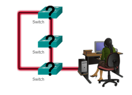
Hostnames are configured on the active networking device. If the device name is not explicitly configured, a factory-assigned default device name is used by Cisco IOS. The default name for a Cisco IOS switch is “Switch.”
Imagine if an internetwork had several switches that were all named with the default name “Switch” (as shown in the figure). This could create considerable confusion during network configuration and maintenance. When accessing a remote device using SSH, it is important to have confirmation that you are connected to the proper device. If all devices were left with their default names, it would be difficult to identify that the proper device is connected.
By choosing names wisely, it is easier to remember, discuss, document, and identify network devices. To name devices in a consistent and useful way requires the establishment of a naming convention that spans the company or, at least, the location. It is a good practice to create the naming convention at the same time as the addressing scheme to allow for continuity within an organization.
Some guidelines for naming conventions are that names should:
- Start with a letter
- Contain no spaces
- End with a letter or digit
- Use only letters, digits, and dashes
- Be less than 64 characters in length
The hostnames used in the device IOS preserve capitalization and lowercase characters. Therefore, it allows you to capitalize a name as you ordinarily would. This contrasts with most Internet naming schemes, where uppercase and lowercase characters are treated identically.
2.2.1.3 Hostnames
Hostnames allow devices to be identified by network administrators over a network or the Internet.
Applying Names Example
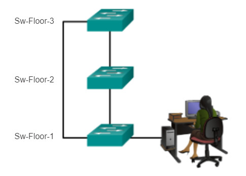
Let’s use an example of three switches connected together in a network, spanning three different floors.
To create a naming convention for switches, take into consideration the location and the purpose of the devices.
For example, in the figure we have named the three switches as Sw-Floor-1, Sw-Floor-2, and Sw-Floor-3.
In the network documentation, we would include these names, and the reasons for choosing them, to ensure continuity in our naming convention as devices are added.
Once the naming convention has been identified, the next step is to apply the names to the devices using the CLI.
2.2.1.4 Configuring Hostnames
From the privileged EXEC mode, access the global configuration mode by entering the configure terminal command:
witch# configure terminal
After the command is executed, the prompt will change to:
Switch(config)#
As shown in the figure, in the global configuration mode, enter the hostname:
Switch(config)# hostname Sw-Floor-1
After the command is executed, the prompt will change to:
Sw-Floor-1 (config)#
Notice that the hostname appears in the prompt. To exit global configuration mode, use the exit command.
Always make sure that your documentation is updated each time a device is added or modified. Identify devices in the documentation by their location, purpose, and address.
Note: To undo the effects of a command, preface the command with the no keyword.
For example, to remove the name of a device, use:
Sw-Floor-1 (config)# no hostname
Switch(config)#
Notice that the no hostname command caused the switch to revert to the default hostname of “Switch.”
In the figure, practice entering a hostname on a switch.
Configure a Hostname
Switch#
configure terminal
Enter configuration commands, one per line. End with CNTL/Z.
Switch(config)#
hostname Sw-Floor-1
Sw-Floor-1(config)#
You successfully configured the switch hostname.
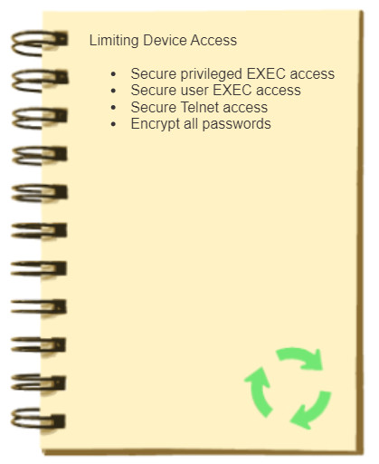
2.2.2 Limiting Access to Device Configurations
2.2.2.1 Securing Device Access
Physically limiting access to network devices by placing them in closets and locked racks is good practice; however, passwords are the primary defense against unauthorized access to network devices. Every device, even home routers, should have locally configured passwords to limit access. Later, we will introduce how to strengthen security by requiring a username along with a password. For now, we will present basic security precautions using only passwords.
As discussed previously, the IOS uses hierarchical modes to help with device security. As part of this security enforcement, the IOS can accept several passwords to allow different access privileges to the device.
The passwords introduced here are:
- Enable password – Limits access to the privileged EXEC mode
- Enable secret – Encrypted, limits access to the privileged EXEC mode
- Console password – Limits device access using the console connection
- VTY password – Limits device access over Telnet
As good practice, use different authentication passwords for each of these levels of access. Although logging in with multiple and different passwords is inconvenient, it is a necessary precaution to properly protect the network infrastructure from unauthorized access.
Additionally, use strong passwords that are not easily guessed. The use of weak or easily guessed passwords continues to be a security issue in many facets of the business world.
Consider these key points when choosing passwords:
- Use passwords that are more than 8 characters in length.
- Use a combination of upper and lowercase letters, numbers, special characters, and/or numeric sequences in passwords.
- Avoid using the same password for all devices.
- Avoid using common words such as password or administrator, because these are easily guessed.
Note: In most of the labs in this course, we will be using simple passwords such as cisco or class. These passwords are considered weak and easily guessable and should be avoided in a work environment. We only use these passwords for convenience in a classroom setting or to illustrate configuration examples.
2.2.2.2 Securing Privileged EXEC Access
To secure privileged EXEC access, use the enable secret password command. An older, less secure variation of this command is the enable password password command. Although either of these commands can be used to establish authentication before access to privileged EXEC (enable) mode is permitted, it is recommended to use the enable secret command. The enable secret command provides greater security because the password is encrypted.
Example command to set passwords:
Switch(config)# enable secret class
The example in the figure illustrates how a password is not requested when first using the enable command. Next the enable secret class command is configured and now privileged EXEC access is secured. Notice that for security reasons, the password is not displayed when it is being entered.
Limiting Device Access
Sw-Floor-1>enable
Sw-Floor-1#
Sw-Floor-1#conf terminal
Sw-Floor-1(config)#enable secret class
Sw-Floor-1(config)#exit
Sw-Floor-1#
Sw-Floor-1#disable
Sw-Floor-1>enable
Password:
Sw-Floor-1#
2.2.2.3 Securing User EXEC Access
The console port of network devices must be secured, at a bare minimum, by requiring the user to supply a strong password. This reduces the chance of unauthorized personnel physically plugging a cable into the device and gaining device access.
The following commands are used in global configuration mode to set a password for the console line:
Switch(config)# line console 0
Switch(config-line)# password cisco
Switch(config-line)# login
From global configuration mode, the command line console 0 is used to enter line configuration mode for the console. The zero is used to represent the first (and in most cases only) console interface.
The second command, password cisco specifies a password for the console line.
The login command configures the switch to require authentication upon login. When login is enabled and a password set, the console user will be prompted to enter a password before gaining access to the CLI.
VTY Password
The vty lines allow access to a Cisco device via Telnet. By default, many Cisco switches support up to 16 vty lines that are numbered 0 to 15. The number of vty lines supported on a Cisco router varies with the type of router and the IOS version. However, five is the most common number of vty lines configured. These lines are numbered 0 to 4 by default, though additional lines can be configured. A password needs to be set for all available vty lines. The same password can be set for all connections. However, it is often desirable that a unique password be set for one line to provide a fall-back for administrative entry to the device if the other connections are in use.
Example commands used to set a password on vty lines:
Switch(config)# line vty 0 15
Switch(config-line)# password cisco
Switch(config-line)# login
By default, the IOS includes the login command on the VTY lines. This prevents Telnet access to the device without authentication. If, by mistake, the no login command is set, which removes the requirement for authentication, unauthorized persons could connect across the network to the line using Telnet. This would be a major security risk.
The figure illustrates the securing of the user EXEC access on the console and Telnet lines.
Sw-Floor-1(config)#line console 0
Sw-Floor-1(config-line)#password cisco
Sw-Floor-1(config-line)#login
Sw-Floor-1(config-line)#exit
Sw-Floor-1(config)#
Sw-Floor-1(config)#line vty 0 15
Sw-Floor-1(config-line)#password cisco
Sw-Floor-1(config-line)#login
Sw-Floor-1(config-line)#
2.2.2.4 Encrypting Password Display
Another useful command prevents passwords from showing up as plain text when viewing the configuration files. This is the service password-encryption command.
This command causes the encryption of passwords to occur when a password is configured. The service password-encryption command applies weak encryption to all unencrypted passwords. This encryption applies only to passwords in the configuration file, not to passwords as they are sent over media. The purpose of this command is to keep unauthorized individuals from viewing passwords in the configuration file.
If you execute the show running-config or show startup-config command prior to the service password-encryption command being executed, the unencrypted passwords are visible in the configuration output. The service password-encryption can then be executed and the encryption will be applied to the passwords. Once the encryption has been applied, removing the encryption service does not reverse the encryption.
In the figure, practice entering the command to configure password encryption.
Configuring Password Encryption
Switch(config)# service password-encryption
Exit global configuration mode and view the running configuration.
Switch(config)#
exit
Switch#
show running-config
!
<output omitted>
!
line con 0
password 7 094F471A1A0A
login
!
line vty 0 4
password 7 03095A0F034F38435B49150A1819
login
!
!
end
Switch#
You successfully encrypted the plain text passwords.
2.2.2.5 Banner Messages
Although requiring passwords is one way to keep unauthorized personnel out of a network, it is vital to provide a method for declaring that only authorized personnel should attempt to gain entry into the device. To do this, add a banner to the device output.
Banners can be an important part of the legal process in the event that someone is prosecuted for breaking into a device. Some legal systems do not allow prosecution, or even the monitoring of users, unless a notification is visible.
The exact content or wording of a banner depends on the local laws and corporate policies. Here are some examples of information to include in a banner:
- “Use of the device is specifically for authorized personnel.”
- “Activity may be monitored.”
- “Legal action will be pursued for any unauthorized use.”
Because banners can be seen by anyone who attempts to log in, the message must be worded very carefully. Any wording that implies that a login is “welcome” or “invited” is not appropriate. If a person disrupts the network after gaining unauthorized entry, proving liability will be difficult if there is the appearance of an invitation.
The creation of banners is a simple process; however, banners should be used appropriately. When a banner is utilized it should never welcome someone to the device. It should detail that only authorized personnel are allowed to access the device. Further, the banner can include scheduled system shutdowns and other information that affects all network users.
The IOS provides multiple types of banners. One common banner is the message of the day (MOTD). It is often used for legal notification because it is displayed to all connected terminals.
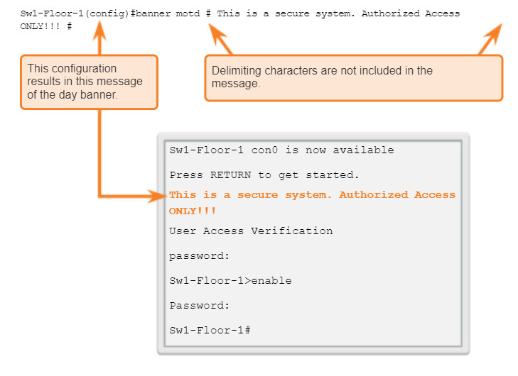
Configure MOTD using the banner motd command from global configuration mode.
The banner motd command requires the use of delimiters to identify the content of the banner message. The banner motd command is followed by a space and a delimiting character. Then, one or more lines of text are entered to represent the banner message. A second occurrence of the delimiting character denotes the end of the message. The delimiting character can be any character as long as it does not occur in the message. For this reason, symbols such as the “#” are often used.
The syntax to configure a MOTD, from global configuration mode is:
Switch(config)# banner motd # message #
Once the command is executed, the banner will be displayed on all subsequent attempts to access the device until the banner is removed.
The example in the figure illustrates a banner configured with the delimiting “#” symbol. Notice how the banner is now displayed when accessing the switch.
Limiting Device Access – MOTD Banner
2.2.3 Saving Configurations
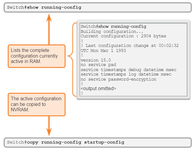
2.2.3.1 Configuration Files
The running configuration file reflects the current configuration applied to a Cisco IOS device. It contains the commands used to determine how the device operates on the network, as shown in Figure 1. Modifying a running configuration affects the operation of a Cisco device immediately.
The running configuration file is stored in the working memory of the device, or random access memory (RAM). This means that the running configuration file is temporarily active while the Cisco device is running (powered on). However, if power to the device is lost or if the device is restarted, all configuration changes will be lost unless they have been saved.
After making changes to a running configuration file, consider these distinct options:
- Return the device to its original configuration.
- Remove all configurations from the device.
- Make the changed configuration the new startup configuration.
The startup configuration file reflects the configuration that will be used by the device upon reboot. The startup configuration file is stored in NVRAM. When a network device has been configured and the running configuration has been modified, it is important to save those changes to the startup configuration file. Doing so prevents changes from being lost due to power failure or a deliberate restart.
Before committing to the changes, use the appropriate show commands to verify the device’s operation. As shown in the figure, the show running-config command can be used to see a running configuration file. When the changes are verified to be correct, use the copy running-config startup-config command at the privileged EXEC mode prompt. The command to save the running configuration to startup configuration file is:
Switch# copy running-config startup-config
After being executed, the running configuration file updates the startup configuration file.
If the changes made to the running configuration do not have the desired effect, it may become necessary to restore the device to its previous configuration. Assuming that we have not overwritten the startup configuration with the changes, we can replace the running configuration with the startup configuration. This is best done by restarting the device using the reload command at the privileged EXEC mode prompt.
When initiating a reload, the IOS will detect that the running config has changes that were not saved to startup configuration. A prompt will appear to ask whether to save the changes made. To discard the changes, enter n or no.
An additional prompt will appear to confirm the reload. To confirm, press Enter. Pressing any other key will abort the process.
For example:
Switch# reload
System configuration has been modified. Save? [yes/no]: n
Proceed with reload? [confirm]
*Apr 13 01:34:15.758: %SYS-5-RELOAD: Reload requested by console. Reload Reason:
Reload Command.
System Bootstrap, Version 12.3(8r)T8, RELEASE SOFTWARE (fc1)
Technical Support: http://www.cisco.com/techsupport
Copyright (c) 2004 by cisco Systems, Inc.
PLD version 0x10
GIO ASIC version 0x127
c1841 processor with 131072 Kbytes of main memory
Main memory is configured to 64 bit mode with parity disabled
If undesired changes are saved to the startup configuration, it may be necessary to clear all the configurations. This requires erasing the startup configuration and restarting the device.
The startup configuration is removed by using the erase startup-config command.
To erase the startup configuration file use erase NVRAM:startup-config or erase startup-config at the privileged EXEC mode prompt:
Switch# erase startup-config
After the command is issued, the switch will prompt you for confirmation:
Erasing the nvram filesystem will remove all configuration files! Continue? [confirm]
Confirm is the default response. To confirm and erase the startup configuration file, press Enter. Pressing any other key will abort the process.
Caution: Exercise caution when using the erase command. This command can be used to erase any file in the device. Improper use of the command can erase the IOS itself or another critical file.
On a switch you must also issue the delete vlan.dat command in addition to the erase startup-config command in order to return the device to its default “out-of-the-box” configuration (comparable to a factory reset):
Switch# delete vlan.dat
Delete filename [vlan.dat]?
Delete flash:vlan.dat? [confirm]
Switch# erase startup-config
Erasing the nvram filesystem will remove all configuration files! Continue? [confirm]
[OK]
Erase of nvram: complete
Switch#
After removing the startup configuration from NVRAM (and deleting the vlan.dat file in the case of a switch), reload the device to remove the current running configuration file from RAM. The device will then load the default startup configuration that was originally shipped with the device into the running configuration.
In Figure 2, practice entering commands to save the running configuration from RAM to NVRAM.
Saving and Erasing the Configuration
Switch# copy running-config startup-config
The configuration in RAM and the configuration in NVRAM are now the same. If you want to restore the switch to its default “out-of-the-box” configuration, you must enter two commands.
First, enter the command that will remove the vlan.dat file.
Switch# delete vlan.dat
Delete filename [vlan.dat]?
Delete flash:vlan.dat? [confirm]
On a real switch, the IOS waits for you to confirm the file name and then confirm the delete. Now enter the command to remove the configuration stored in NVRAM.
Switch# erase startup-config
Erasing the nvram filesystem will remove all configuration files! Continue? [confirm]
[OK]
Erase of nvram: complete
On a real switch, the IOS waits for you to confirm the erase command. The final step to return a switch to its default configuration is to reboot the switch.
Switch# reload
Proceed with reload? [confirm]
C2960 Boot Loader (C2960-HBOOT-M) Version 12.2(25r)FX, RELEASE SOFTWARE (fc4)
Cisco WS-C2960-24TT (RC32300) processor (revision C0) with 21039K bytes of memory.
2960-24TT starting...
<output omitted>
Enter privileged EXEC mode and view the current configuration stored in NVRAM.
Switch> enable
Switch# show startup-config
startup-config is not present
Switch#
The switch is restored to its default “out-of-the-box” configuration.
You successfully saved and then erased the switch configuration.
2.2.3.2 Capturing Text
Backup Configurations with Text Capture
In addition to saving running configurations to the startup configuration, configuration files can also be saved and archived to a text document. This sequence of steps ensures that a working copy of the configuration files is available for editing or reuse later.
In Figure 1, configuration files can be saved and archived to a text document using Tera Term.
The steps are:
- On the File menu, click Log.
- Choose the location. Tera Term will begin capturing text.
- After capture has been started, execute the show running-config or show startup-config command at the privileged EXEC prompt. Text displayed in the terminal window will be placed into the chosen file.
- When the capture is complete, select Close in the Tera Term: Log window.
- View the output to verify that it was not corrupted.
Similarly, Figure 2 shows how files can be saved and archived in a text document using HyperTerminal.
Restoring Text Configurations
A configuration file can be copied from storage to a device. When copied into the terminal, the IOS executes each line of the configuration text as a command. The file will probably require editing before copying. It is advisable to change the encrypted passwords to plain text and remove the parameter, either the number 5 or 7, which specifies that the password is encrypted. Non-command text such as “–More–” and IOS messages must be removed. This process is discussed in the lab.
Further, at the CLI, the device must be set at the global configuration mode to receive the commands from the text file being copied.
When using Tera Term, the steps are:
- Edit text to remove non-commands and save.
- On the File menu, click Send file.
- Locate the file to be copied into the device and click Open.
- Tera Term will paste the file into the device.
The text in the file will be applied as commands in the CLI and become the running configuration on the device. This is a convenient method for manually configuring a device.
[tabs type=”horizontal”]
[tabs_head]
[tab_title]Saving to a Text File in Tera Term[/tab_title]
[tab_title]Saving to a Text File in HyperTerminal[/tab_title]
[/tabs_head]
[tab]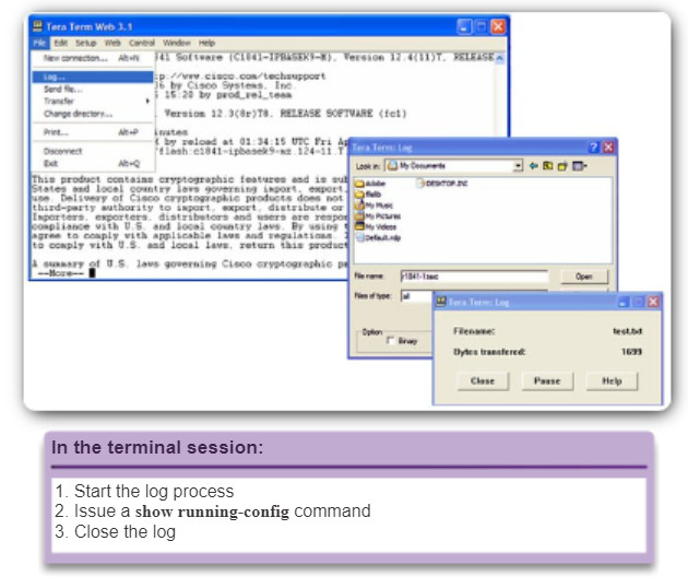 [/tab]
[tab]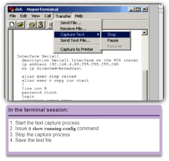 [/tab]
[/tabs]
2.2.3.3 Packet Tracer – Configuring Initial Switch Settings
In this activity, you will perform basic switch configurations. You will secure access to the command-line interface (CLI) and console ports using encrypted and plain text passwords. You will also learn how to configure messages for users logging into the switch. These banners are also used to warn unauthorized users that access is prohibited.
Packet Tracer – Configuring Initial Switch Settings Instructions ./.
Packet Tracer – Configuring Initial Switch Settings – PKA ./.
2.3 Address Schemes
2.3.1 Ports and Addresses
2.3.1.1 IP Addressing of Devices
The use of IP addresses, whether IPv4 or IPv6, is the primary means of enabling devices to locate one another and establish end-to-end communication on the Internet. In fact, in any internetwork, IP addresses are essential for devices to communicate from source to destination and back.
Each end device on a network must be configured with IP addresses. Some examples of end devices are:
- Computers (work stations, laptops, file servers, web servers)
- Network printers
- VoIP phones
- Security cameras
- Smart phones
- Mobile handheld devices (such as wireless barcode scanners)
The structure of an IPv4 address is called dotted decimal notation and is represented with four decimal numbers between 0 and 255. IPv4 addresses are numbers assigned to individual devices connected to a network. They are logical in nature, in that they provide information about the location of the device.
With the IP address, a subnet mask is also necessary. A subnet mask is a special type of IPv4 address that, coupled with the IP address, determines which particular subnet of a larger network the device is a member.
IP addresses can be assigned to both physical ports and virtual interfaces on devices. A virtual interface means that there is no physical hardware on the device associated with it.
2.3.1.2 Interfaces and Ports
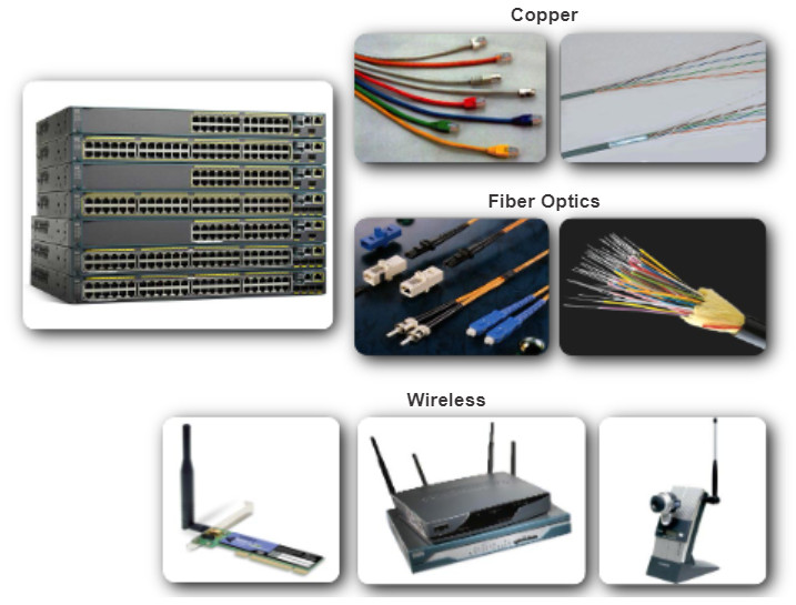
Network communications depend on end user device interfaces, networking device interfaces, and the cables that connect them.
Each physical interface has specifications, or standards, that define it; a cable connecting to the interface must be designed to match the physical standards of the interface. Types of network media include twisted-pair copper cables, fiber-optic cables, coaxial cables, or wireless. Different types of network media have different features and benefits. Not all network media has the same characteristics and is appropriate for the same purpose. Some of the differences between various types of media include:
- Distance the media can successfully carry a signal
- Environment in which the media is to be installed
- Amount of data and the speed at which it must be transmitted
- Cost of the media and installation
Not only does each link on the Internet require a specific network media type, but each link also requires a particular network technology. Ethernet is the most common local area network (LAN) technology used today. Ethernet ports are found on end user devices, switch devices, and other networking devices that can physically connect to the network using a cable. For a cable to connect devices using an Ethernet port, the cable must have the correct connector, an RJ-45.
Cisco IOS switches have physical ports for devices to connect to, but also have one or more switch virtual interfaces (SVIs). These are virtual interfaces, because there is no physical hardware on the device associated with it; an SVI is created in software. The virtual interface provides a means to remotely manage a switch over a network using IPv4. Each switch comes with one SVI appearing in the default configuration “out-of-the-box.” The default SVI is interface VLAN1.
2.3.2 Addressing Devices
2.3.2.1 Configuring a Switch Virtual Interface
To access the switch remotely, an IP address and a subnet mask must be configured on the SVI:
- IP address – Together with subnet mask, uniquely identifies end device on the internetwork
- Subnet mask – Determines which part of a larger network is used by an IP address
For now the focus is IPv4; later you will explore IPv6.
You will learn the meaning behind all of these IP addresses soon, but for now the point is to quickly configure the switch to support remote access. The figure displays the command to enable IP connectivity to S1, using IP address 192.168.10.2:
- interface vlan 1 – Used to navigate to the interface configuration mode from the global configuration mode
- ip address 192.168.10.2 255.255.255.0 – Configures the IP address and subnet mask for the switch (this is just one of many possible combinations for an IP address and subnet mask)
- no shutdown – Administratively enables the interface to an active state
After these commands are configured, the switch has all the IP elements ready for communication over the network.
Note: The switch will still need to have one or more physical ports configured, as well as the VTY lines, to complete the configuration which enables remote management of the switch.
Practice configuring a switch virtual interface by entering commands in the figure.
Configuring a Switch Virtual Interface
Switch(config)# interface vlan 1
Configure the IP address as ‘192.168.10.2’ and the subnet mask as ‘255.255.255.0’.
Switch(config-if)# ip address 192.168.10.2 255.255.255.0
Activate the interface.
Switch(config-if)# no shutdown
%LINK-5-CHANGED: Interface Vlan1, changed state to up

Switch(config-if)#
You successfully configured the VLAN 1 interface.
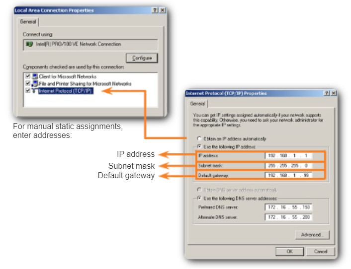
2.3.2.2 Manual IP Address Configuration for End Devices
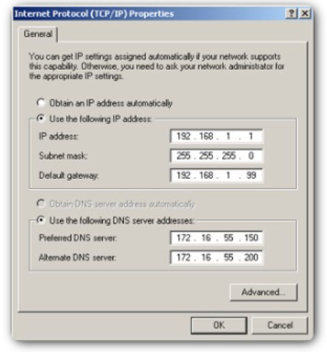
In order for an end device to communicate over the network, it must be configured with the correct IP address information. Much like a switch SVI, the end device must be configured with an IP address and subnet mask. This information is configured on the PC settings.
All of these settings must be configured on an end device in order for it to properly connect to the network. This information is configured under the PC network settings. In addition to IP address and subnet mask information, it is also possible to configure default gateway and DNS server information, as shown in the figure.
The default gateway address is the IP address of the router interface used for network traffic to exit the local network. The default gateway is an IP address that is often assigned by the network administrator and is used when traffic must be routed to another network.
The DNS server address is the IP address of the Domain Name System (DNS) server, which is used to translate IP addresses to web addresses, such as www.cisco.com. All devices on the Internet are assigned and reached via an IP address. However, it is easier for people to remember names over numbers. Therefore, websites are given names for simplicity. The DNS server is used to maintain the mapping between the IP addresses and names of various devices.
2.3.2.3 Automatic IP Address Configuration for End Devices
IP address information can be entered into the PC manually, or using Dynamic Host Configuration Protocol (DHCP). DHCP allows end devices to have IP information automatically configured.
DHCP is a technology that is used in almost every business network. The best way to understand why DHCP is so popular is by considering all the extra work that would have to take place without it.
DHCP enables automatic IPv4 address configuration for every end device in a network with DHCP enabled. Imagine the amount of time that would be consumed if every time you connected to the network you had to manually enter the IP address, the subnet mask, the default gateway, and the DNS server. Multiply that by every user and every one of their devices on the network and you see the problem.
DHCP is an example of technology at its best. One of the primary purposes of any technology is to make it easier to perform the tasks they want to do or need to do. With DHCP, the end user walks into the area served by a given network, plugs in an Ethernet cable or enables a wireless connection, and they are immediately allocated the necessary IPv4 information required to fully communicate over the network.
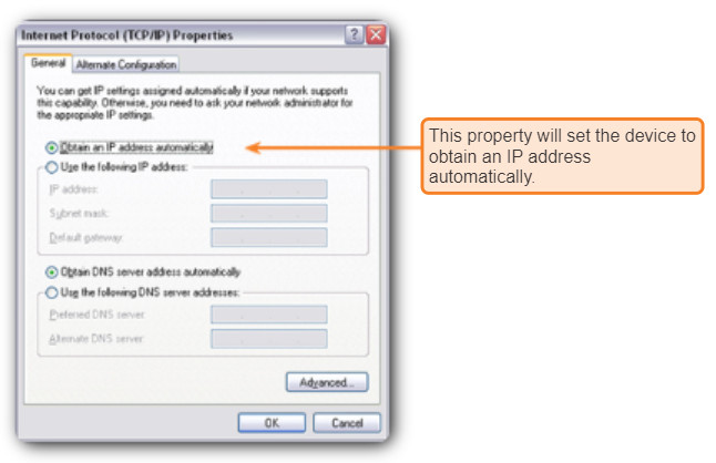
As shown in Figure 1, to configure DHCP on a Windows PC, you only need to select “Obtain an IP address automatically” and “Obtain DNS server address automatically”. Your PC will be assigned information from an IP address pool and associated IP information set up on the DHCP server.
It is possible to display the IP configuration settings on a Windows PC by using the ipconfig command at the command prompt. The output will show the IP address, subnet mask, and gateway that the PC received from the DHCP server.
Practice displaying the IP address of a Windows PC by entering commands in Figure 2.
Verifying Windows PC IP Configuration
C:\>
ipconfig

Windows IP Configuration

Ethernet adapter Local Area Connection:

Connection-specific DNS Suffix . : cisco.com
Link-local IPv6 Address . . . . . : fe80::b0ef:ca42:af2c:c6c7%16
IPv4 Address. . . . . . . . . . . : 10.82.240.197
Subnet Mask . . . . . . . . . . . : 255.255.255.0
Default Gateway . . . . . . . . . : 10.82.240.198

-------------------------------------
You successfully displayed the IP configuration on a Windows PC.
2.3.2.4 IP Address Conflicts
If a static (manual) IP address is defined for a network device, for example, a printer, and then a DHCP server is installed, duplicate IP address conflicts may occur between the network device and a PC obtaining automatic IP addressing information from the DHCP server. The conflict also may occur if you manually define a static IP address to a network device during a network failure involving the DHCP server; after the network failure resolves and the DHCP server becomes accessible over the network, the conflict arises.
To resolve such an IP addressing conflict convert the network device with the static IP address to a DHCP client; or on the DHCP server, exclude the static IP address of the end device from the DHCP scope.
The second solution requires that you have administrative privileges on the DHCP server and that you are familiar with configuring DHCP on a server.
You may also encounter IP addressing conflicts when manually configuring IP on an end device in a network that only uses static IP addresses. In this case you must determine which IP addresses are available on the particular IP subnet and configure accordingly. This case illustrates why it is so important for a network administrator to maintain detailed documentation, including IP address assignments, for end devices.
Note: Usually static IP addresses are used with servers and printers in a small- to medium-sized business network, while employee devices use DHCP-allocated IP address information.
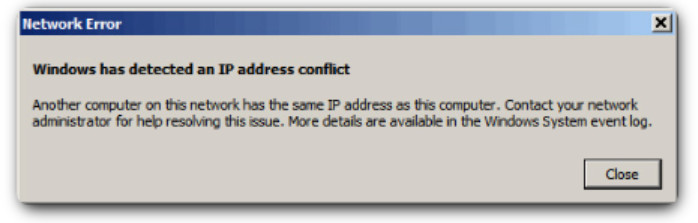
2.3.2.5 Packet Tracer – Implementing Basic Connectivity
In this activity, you will first perform basic switch configurations. Then you will implement basic connectivity by configuring IP addressing on switches and PCs. When the IP addressing configuration is complete, you will use various show commands to verify configurations and use the ping command to verify basic connectivity between devices.
Packet Tracer – Implementing Basic Connectivity Instructions ./.
Packet Tracer – Implementing Basic Connectivity – PKA ./.
2.3.3 Verifying Connectivity
2.3.3.1 Test the Loopback Address on an End Device
The figure shows the first step in the testing sequence. The ping command is used to verify the internal IP configuration on a local host. This test is accomplished by using the ping command on a reserved address called the loopback (127.0.0.1). The loopback address, 127.0.0.1, is defined by the TCP/IP protocol as a reserved address that routes packets back to the host.
Ping commands are entered into a command line on the local host using the syntax:
C:\> ping 127.0.0.1
The reply from this command would look something like this:
Reply from 127.0.0.1: bytes=32 time<1ms TTL=128
Reply from 127.0.0.1: bytes=32 time<1ms TTL=128
Reply from 127.0.0.1: bytes=32 time<1ms TTL=128
Reply from 127.0.0.1: bytes=32 time<1ms TTL=128
Ping statistics for 127.0.0.1:
Packets: Sent = 4, Received = 4, Lost = 0 (0% loss),
Approximate round trip times in milli-seconds:
Minimum = 0ms, Maximum = 0ms, Average = 0ms
The result indicates that four test packets of 32 bytes each were sent and returned from host 127.0.0.1 in a time of less than 1 ms. This successful ping request verifies that the network interface card, drivers, and the TCP/IP implementation are all functioning correctly.
Practice testing a loopback address by entering commands in Figure 2.
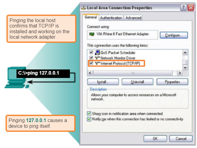
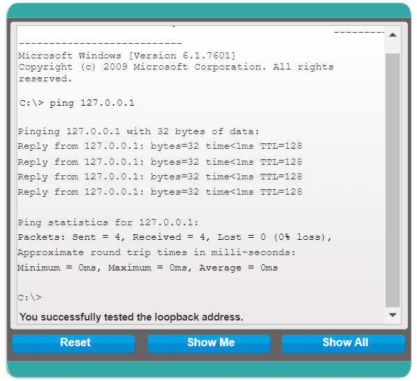
2.3.3.2 Testing the Interface Assignment
In the same way that you use commands and utilities to verify a host configuration, you use commands to verify the interfaces of intermediary devices. The IOS provides commands to verify the operation of router and switch interfaces.
Verifying the Switch Interfaces
Examining S1 and S2, you use the show ip interface brief command to verify the condition of the switch interfaces, as shown in the figure. The IP address assigned to VLAN 1 interface on S1 is 192.168.10.2. The IP address assigned to VLAN 1 interface on S2 is 192.168.10.3. The physical interfaces F0/1 and F0/2 on S1 are operational, as are the physical interfaces F0/1 and F0/2 on S2.
Practice verification of a VLAN interface by entering commands in the figure.
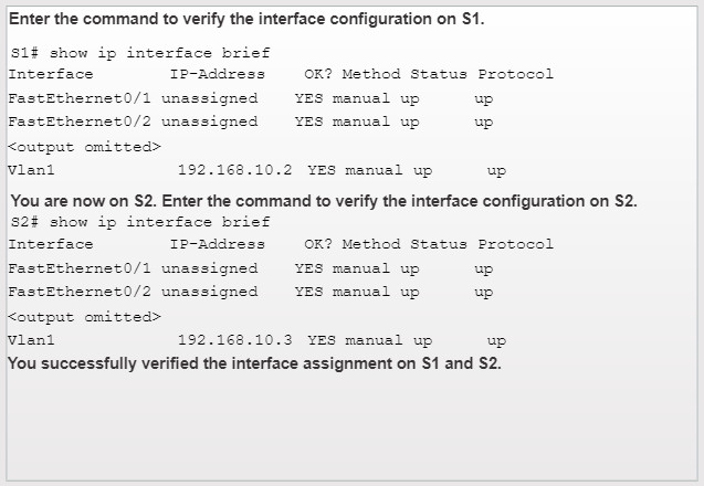
2.3.3.3 Testing End-to-End Connectivity
Testing PC-to-Switch Connectivity
The ping command can be used on a PC, just as on a Cisco IOS device. The figure shows that a ping from PC1 to the IP address of the S1 VLAN 1 interface, 192.168.10.2, should be successful.
Testing End-to-End Connectivity
The IP address of PC1 is 192.168.10.10, with subnet mask 255.255.255.0, and default gateway 192.168.10.1.
The IP address of PC2 is 192.168.10.11, with subnet mask 255.255.255.0, and default gateway 192.168.10.1.
A ping from PC1 to PC2 should also be successful. A successful ping from PC1 to PC2 verifies end-to-end connectivity in the network!
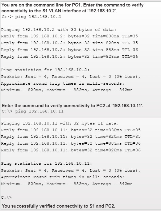
2.3.3.4 Lab – Building a Simple Network
In this lab, you will complete the following objectives:
- Part 1: Set Up the Network Topology (Ethernet only)
- Part 2: Configure PC Hosts
- Part 3: Configure and Verify Basic Switch Settings
Lab – Building a Simple Network ./.
2.3.3.5 Lab – Configuring a Switch Management Address
In this lab, you will complete the following objectives:
- Part 1: Configure a Basic Network Device
- Part 2: Verify and Test Network Connectivity
Lab – Configuring a Switch Management Address ./.
2.4 Summary
2.4.1 Summary
2.4.1.1 Class Activity – Tutor Me
Tutor me
Students will work in pairs. Packet Tracer is required for this activity.
Assume that a new colleague has asked you for an orientation to the Cisco IOS CLI. This colleague has never worked with Cisco devices before.
You explain the basic CLI commands and structure, because you want your colleague to understand that the CLI is a simple, yet powerful, command language that can be easily understood and navigated.
Use Packet Tracer and one of the activities available in this chapter as a simple network model (for example, Lab Activity 2.3.3.5 LAB – Configuring a Switch Management Address).
Focus on these areas:
- While the commands are technical, do they resemble any statements from plain English?
- How is the set of commands organized into subgroups or modes? How does an administrator know which mode he or she is currently using?
- What are the individual commands to configure the basic settings of a Cisco device? How would you explain this command in simple terms? Use parallels to real life whenever appropriate.
Suggest how to group different commands together according to their modes so that a minimum number of moves between modes will be needed.
Class Activity – Tutor Me! Instructions ./.
2.4.1.2 Packet Tracer – Skills Integration Challenge
As a recently hired LAN technician, your network manager has asked you to demonstrate your ability to configure a small LAN. Your tasks include configuring initial settings on two switches using the Cisco IOS and configuring IP address parameters on host devices to provide end-to-end connectivity. You are to use two switches and two hosts/PCs on a cabled and powered network.
Packet Tracer – Skills Integration Challenge Instructions ./.
Packet Tracer – Skills Integration Challenge – PKA ./.
2.4.1.3 Summary
Cisco IOS is a term that encompasses a number of different operating systems, which runs on various networking devices. The technician can enter commands to configure, or program, the device to perform various networking functions. Cisco IOS routers and switches perform functions that network professionals depend upon to make their networks operate as expected.
The services provided by the Cisco IOS are generally accessed using a command-line interface (CLI), which is accessed by either the console port, the AUX port, or through telnet or SSH. Once connected to the CLI, network technicians can make configuration changes to Cisco IOS devices. The Cisco IOS is designed as a modal operating system, which means a network technician must navigate through various hierarchical modes of the IOS. Each mode supports different IOS commands.
The Cisco IOS Command Reference is a collection of online documents that describe in detail the IOS commands used on Cisco devices, such as Cisco IOS routers and switches.
Cisco IOS routers and switches support a similar modal operating system, support similar command structures, and support many of the same commands. In addition, both devices have identical initial configuration steps when implementing them in a network.
This chapter introduced the Cisco IOS. It detailed the various modes of the Cisco IOS and examined the basic command structure that is used to configure it. It also walked through the initial settings of a Cisco IOS switch device, include setting a name, limiting access to the device configuration, configuring banner messages, and saving the configuration.
The next chapter explores how packets are moved across the network infrastructure and introduce you to the rules of packet communication.