Lab 1-2: Troubleshooting Switch Media Issues
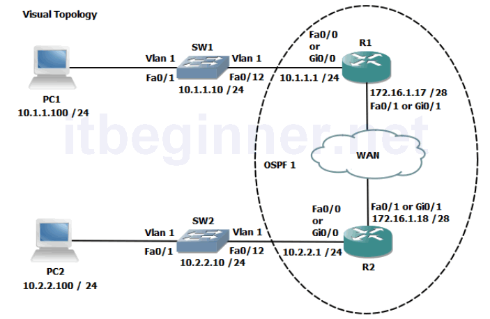
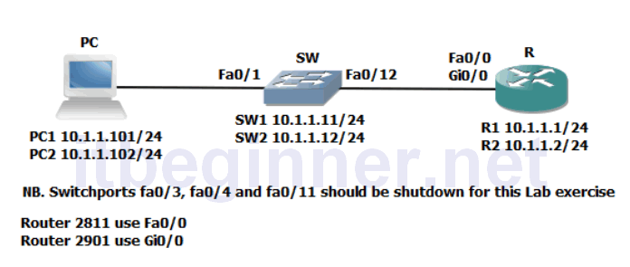
Visual Topology
Command Lis
| Command | Description |
|---|---|
| Configure Terminal | Enters global configuration mode. |
| Copy run start | Saves the dynamic running-config to NVRAM. |
| Duplex full / Half / Auto | Enables the interface duplex setting. |
| Enable | Enters privilege EXEC mode |
| Interface Fastethernet 0/0 | Specifies interface fa0/0 |
| Interface Gigabitethernet 0/0 | Specifies interface gi0/0 |
| Shutdown/ No Shutdown | Disables or enable an interface |
| Ping ip-address or hostname | Checks IP connectivity |
| Show Interface Fastethernet 0/0 | Displays information about interface fa0/0 |
| Show Interface Gigabitethernet 0/0 | Displays information about interface gi0/0 |
| Show IP Interface Brief | Displays a brief summary of the device interfaces |
| Speed 10/100/1000/auto | Sets the speed of an interface |
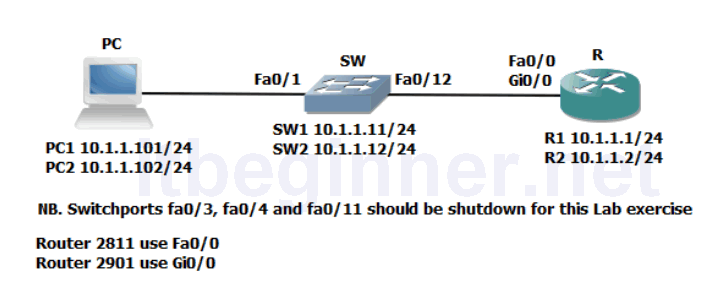
Physical Topology Diagram
- Task 1: Lab setup.
- Task 2: Connectivity issues between the PC and the Switch.
- Task 3: Connectivity issues between the Switch and the Router.
Lab 1-2: Troubleshooting Switch Media Issues
Task 1: Lab setup.
Step 1: Make sure that interfaces fa0/3, fa0/4 and fa0/11 are shutdown on your Switch.
Task 2: Connectivity issues between the PC and the Switch.
Step 1: Check the connectivity between the PC and the Switch using the Ping command, if the Ping fails check the status of Switch interface fa0/1 and verify that its status is up/up. If the interface is administratively down issue the No Shutdown command to bring it up.
Step 2: Enter the correct interface mode for the Switch SVI (management interface ) and shut the interface down. Check the IP connectivity between the PC and the Switch, this should now fail.
Enable the SVI (management interface) and check that IP connectivity has been restored.
Task 3: Connectivity issues between the Switch and the Router.
Step 1: Check that interface fa0/12 on the Switch isn’t administratively shutdown, rectify if it is.
Step 2: Access the console port of the Router using the access method described by the instructor.
Give the router a hostname of R1 or R2
Step 3: Enter the interface configuration mode this will be either fa0/0 if you are using a 2811 Router or gi0/0 if you are using a 2901 Router.
Give the interface an IP address of either 10.1.1.1/24 (R1 only) or 10.1.1.2/24 (R2 only).
Try and Ping the IP address of your switch. Was this successful?
If not check the status of the interface, what do you notice?
Rectify the condition and try to Ping the switch again. Only when you have full IP connectivity between the Router and the Switch move on to the next step.
Step 4: Access the interface (fa0/0 or gi0/0) configuration mode on the Router and change the speed setting to 10, now access the CLI on the Switch and enter the interface fa0/12 configuration mode and set the speed to 100.
Check the status of the interfaces connecting the Switch and Router together, make a note of their layer 1 and layer 2 states.
Would you expect connectivity when there is a speed mis-match?
Reconfigure the Router (interface fa0/0 or gi0/0) to match the speed of the switch, remember best working practice suggests you shutdown the interface before making any changes and after you have reconfigured the interface enter the no shut command.
Verify connectivity before moving on to the next step.
Step 5: Configure Switch interface fa0/12 to half duplex and configure Router interface (fa0/0 or gi0/0) to full duplex.
Check the layer 1 and layer 2 status of the connecting interfaces and record your results below.
Once you are ready to move on, reconfigure Switch interface fa0/12 to full duplex, check IP connectivity and save your running-config on both devices.
Lab Answer Keys:
[sociallocker id=”4139″]
Task 1: Lab setup
Step 1: Make sure that interfaces fa0/3, fa0/4 and fa0/11 are shutdown on your Switch.
SW#conf t
SW(config)#interface range fa0/3-4, fa0/11
SW(config-if-range)#shutdown
Task 2: Connectivity issues between the PC and the Switch.
Step 2: Enter the correct interface mode for the Switch SVI (management interface ) and shut the interface down. Check the IP connectivity between the PC and the Switch, this should now fail.
SW#conf t
SW(config)#int vlan 1
SW(config-if)#shut
Enable the SVI (management interface) and check that IP connectivity has been restored.
SW(config-if)#no shut
Task 3: Connectivity issues between the Switch and the Router.
Step 1: Check that interface fa0/12 on the Switch isn’t administratively shutdown, rectify if it is.
SW#sh interface fa0/12
Step 2: Access the console port of the Router using the access method described by the instructor.
Give the router a hostname of R1 or R2
Router#conf t
Router(config)#host R1
or
Router(config)#host R1
Step 3: Enter the interface configuration mode this will be either fa0/0 if you are using a 2811 Router or gi0/0 if you are using a 2901 Router.
Give the interface an IP address of either 10.1.1.1/24 (R1 only) or 10.1.1.2/24 (R2 only).
R1 only.....
R1#conf t
R1(config)#interface fa0/0
or
R1(config)#interface gi0/0
R1(config-if)#ip address 10.1.1.1 255.255.255.0
R1(config-if)#no shut
R2 only.....
R2#conf t
R2(config)#interface fa0/0
or
R2(config)#interface gi0/0
R2(config-if)#ip address 10.1.1.2 255.255.255.0
R2(config-if)#no shut
Try and Ping the IP address of your switch. Was this successful?
The ping should work if the Switch interface and the Routers interface are both up/up
If not check the status of the interface, what do you notice?
Use the sh interface command to display their current status
Rectify the condition and try to Ping the switch again. Only when you have full IP connectivity between the Router and the Switch move on to the next step.
Step 4: Access the interface (fa0/0 or gi0/0) configuration mode on the Router and change the speed setting to 10, now access the CLI on the Switch and enter the interface fa0/12 configuration mode and set the speed to 100.
R(config-if)#speed 10
SW(config-if)#speed 100
Check the status of the interfaces connecting the Switch and Router together, make a note of their layer 1 and layer 2 states.
Use the either sh interface or sh ip interface brief (remember show commands are run from privilege mode)
Would you expect connectivity when there is a speed mis-match?
NO. Layer 1 connections depend on the same speed being used at both ends of the connection.
Reconfigure the Router (interface fa0/0 or gi0/0) to match the speed of the switch, remember best working practice suggests you shutdown the interface before making any changes and after you have reconfigured the interface enter the no shut command.
Verify connectivity before moving on to the next step.
Step 5: Configure Switch interface fa0/12 to half duplex and configure Router interface (fa0/0 or gi0/0) to full duplex.
Switch configuration
SW#conf t
SW(config)#int fa0/12
SW(config-if)#shut
SW(config-if)#duplex half
SW(config-if)#no shut
Router configuration
R#conf t
R(config)#int fa0/0
or
R(config)#int gi0/0
R(config-if)#shut
R(config-if)#duplex full
R(config-if)#no shut
Check the layer 1 and layer 2 status of the connecting interfaces and record your results below.
Duplex mis-matches produce intermittent results but does allow traffic to pass between devices.
Once you are ready to move on, reconfigure Switch interface fa0/12 to full duplex, check IP connectivity and save your running-config on both devices.
#copy run start
[/sociallocker]