Lab 4-1: Enhancing a Switched Network
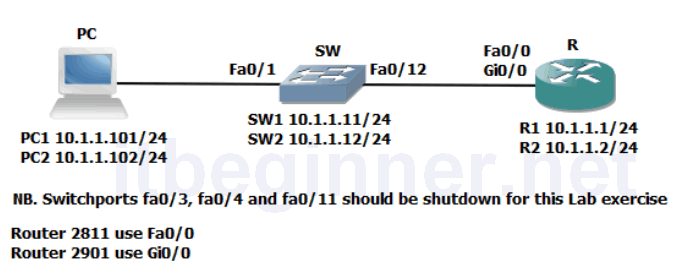
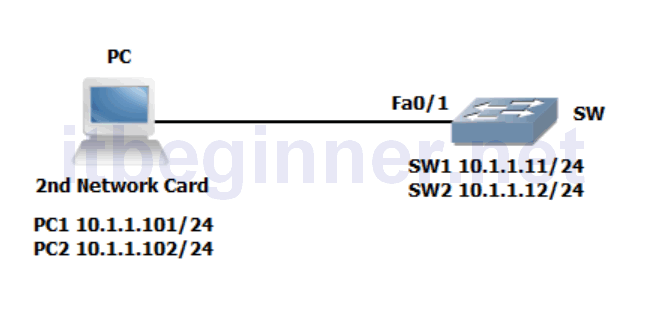
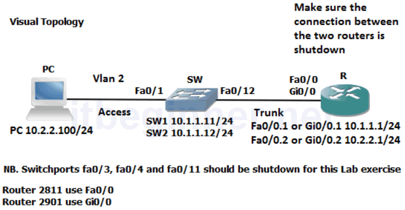
Visual Topology
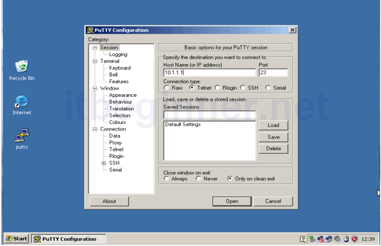
Command Line
| Command | Description |
|---|---|
| encapsulation dot1q vlan | Enables IEEE 802.1Q encapsulation on a routers sub-interface |
| no ip address | Removes any ip address currently configured on the interface |
| show interfaces trunk | Displays trunking information |
| show vlan | Displays vlan information |
| show vlans | Verify the vlan and trunking configuration on a router on a stick |
| switchport access vlan vlan | Assign a port to a vlan |
| switchport mode mode | Defines DTP modes options available are access, trunk, dynamic desirable or dynamic auto |
| switchport trunk allowed vlan vlan list | Filters which vlans are permitted over a trunk connection. |
| vlan number | Creates a vlan |
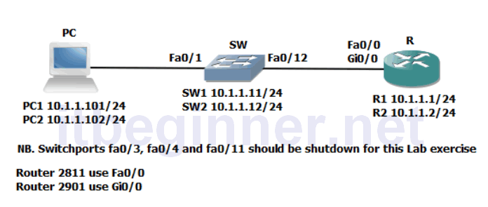
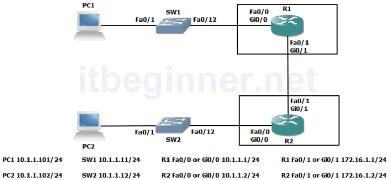
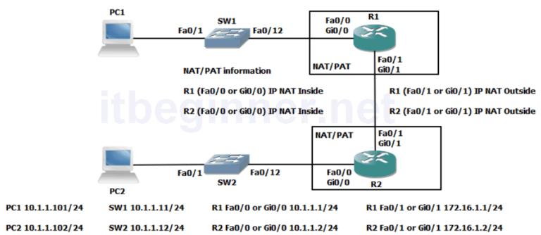
Physical Topology Diagram
- Task 1: Creating a VLAN and assigning Switchports.
- Task 2: Configure a Trunk connection on a Router.
Lab 4-1: Enhancing a Switched Network
Task 1: Creating a VLAN and assigning Switchports.
Step 1: Access the CLI on the router and make sure the connection between the two routers is shutdown.
Step 2: Access the CLI on the switch.
Step 3: Create vlan 2 on your switch and name it SALES
SWx(config)#vlan 2
SWx(config-vlan)#name SALES
Step 4: Re-assign interface fa0/1 to vlan 2
SWx(config-if)#switchport mode access
SWx(config-if)#switchport access vlan 2
Step 5: Configure Fa0/12 as a trunk connection
SWx(config-if)#switchport mode trunk
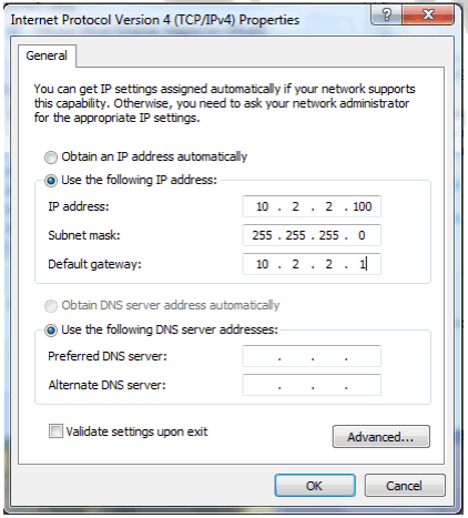
Step 6: Change the IP address on the PC to 10.2.2.100 with a 255.255.255.0 mask and a default gateway of 10.2.2.1
Step 7: From your PC try and Ping the IP address of your switch.
This should fail! Why ?
Task 2: Configure a Trunk connection on a Router.
Now that we have configured the switch to support a trunk connection between itself and the router, the next stage involves us setting up the router so it understands the IEEE 802.1Q frame encapsulation.
Step 1: Access the CLI on the router.
Step 2: Navigate to the interface mode which connects the router to the switch. Hint.. fa0/0 or gi0/0
Step 3: Shutdown the interface.
Step 4: Remove any current IP address using the no ip address command.
Step 5: Create a new sub-interface using the following command.
Rx(config)#interface fa0/0.1
or
Rx(config)#interface gi0/0.1
Step 6: Assign an ip address of 10.1.1.1 255.255.255.0
Step 7: Issue the following command to support IEEE 801.1Q encapsulation linking it to vlan 1 and make this the native vlan.
Rx(config-subif)#encap dot1q 1 native
Step 8: Create a second sub-interface
Rx(config)interface fa0/0.2
or
Rx(config)interface gi0/0.2
Step 8: Assign an ip address of 10.2.2.1 255.255.255.0
Step 9: Setup IEEE 802.1Q encapsulation with a link to vlan 2
Rx(config-subif)#encap dot1q 2
What is the difference between the native vlan and a non-native vlan ?
Step 10: Issue the no shutdown command on the physical interface, this will automatically enable all sub-interfaces.
Step 11: Check your PC can ping its default gateway.
Step 12: Try and ping the IP address of the switch, this should now be successful.
If it fails then check the following.
The switch will need a default gateway set to 10.1.1.1 because the path of the ping from the PC to the switch is via the router.
Explanation: The port attached to the PC has been assigned to Vlan 2 but the IP address of the switch is still in vlan 1, therefore the Ping packet will travel from the PC to its def ault gateway (the router) because the source IP address and the destination IP address are not located in the same IP subnet. The router upon receiving the Ping packet will direct it to sub interface fa0/0.2 or gi0/0.2 because it’s been linked to vlan 2, i t will then examine the destination IP address after stripping the layer 2 header and redirect it out of sub-interface fa0/0.1 or gi0/0.1 but it will need to rebuild a new layer 2 header before going across the trunk to the switch.
Step 13: Save all your configs.
Lab Answer Keys:
[sociallocker id=”4139″]
Task 1: Creating a VLAN and assigning Switchports.
Step 2: Access the CLI on the switch.
Step 3: Create vlan 2 on your switch and name it SALES
SW>en
SW#conf t
SW(config)#vlan 2
SW(config-vlan)#name SALES
Step 4: Re-assign interface fa0/1 to vlan 2
SW(config-vlan)#int fa0/1
SW(config-if)#switchport mode access
SW(config-if)#switchport access vlan 2
Step 5: Configure Fa0/12 as a trunk connection
SW(config-if)#int fa0/12
SW(config-if)#switchport mode trunk
Step 7: From your PC try and Ping the IP address of your switch.
This should fail! Why ?
Because the IP address of the switch is assigned to Vlan 1 and the port connected to the PC is now in Vlan 2 (logically separated) Routing is required between the two Vlan’s.
Task 2: Configure a Trunk connection on a Router.
Now that we have configured the switch to support a trunk connection between itself and the router, the next stage involves us setting up the router so it understands the IEEE 802.1Q frame encapsulation.
Step 1: Access the CLI on the router.
Step 2: Navigate to the interface mode which connects the router to the switch. Hint.. fa0/0 or gi0/0
R>en
R#conf t
R(config)#int fa0/0
or
R(config)#int gi0/0
Step 3: Shutdown the interface.
R(config-if)#shut
Step 4: Remove any current IP address using the no ip address command.
R(config-if)#no ip address
Step 5: Create a new sub-interface using the following command.
R(config)interface fa0/0.1
or
R(config)interface gi0/0.1
Step 6: Assign an ip address of 10.1.1.1 255.255.255.0
R(config-subif)#ip address 10.1.1.1 255.255.255.0
Step 7: Issue the following command to support IEEE 801.1Q encapsulation linking it to vlan 1 and make this the native vlan.
R(config-subif)#encap dot1q 1 native
Step 8: Create a second sub-interface
R(config)#interface fa0/0.2
or
R(config)#interface gi0/0.2
Step 8: Assign an ip address of 10.2.2.1 255.255.255.0
R(config-subif)#ip address 10.2.2.1 255.255.255.0
Step 9: Setup IEEE 802.1Q encapsulation with a link to vlan 2
R(config-subif)#encap dot1q 2
What is the difference between the native vlan and a non-native vlan ?
Native is untagged across a trunk connection, default id vlan 1.
Step 10: Issue the no shutdown command on the physical interface, this will automatically enable all sub-interfaces.
R(config-subif)#exit
R(config)#int fa0/0
or
R(config)#int gi0/0
R(config-if)#no shut
Step 11: Check your PC can ping its default gateway.
Step 12: Try and ping the IP address of the switch, this should now be successful.
If it fails then check the following.
The switch will need a default gateway set to 10.1.1.1 because the path of the ping from the PC to the switch is via the router.
Explanation: The port attached to the PC has been assigned to Vlan 2 but the IP address of the switch is still in vlan 1, therefore the Ping packet will travel from the PC to its default gateway (the router) because the source IP address and the destination IP address are not located in the same IP subnet. The router upon receiving the Ping packet will direct it to sub interface fa0/0.2 or gi0/0.2 because it’s been linked to vlan 2, it will then examine the destination IP address after stripping the layer 2 header and redirect it out of sub-interface
fa0/0.1 or gi0/0.1 but it will need to rebuild a new layer 2 header before going across the trunk to the switch.
[/sociallocker]