
Physical Topology Diagram
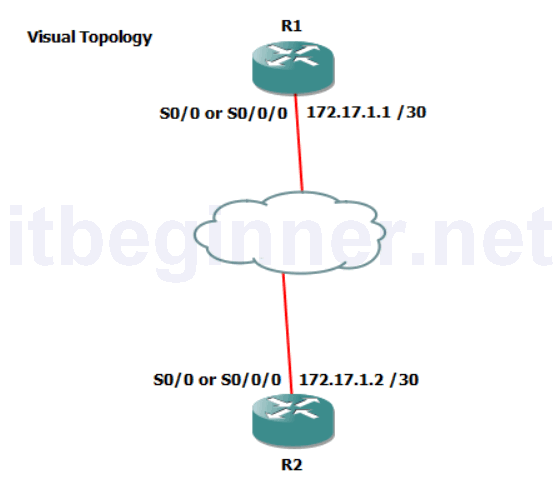
- Visual Topology
- Command Line
- Task 1: Using HDLC
- Task 2: Configuring PPP
- Task 3: Setting up PPP authentication
Visual Topology
Command Line
| Command | Description |
|---|---|
| debug ppp authentication | Displays the PPP authentication process in real time |
| debug ppp negotiation | Displays the PPP negotiation packet exchange |
| encapsulation HDLC | Enables HDLC encapsulation on an interface |
| encapsulation PPP | Enables PPP encapsulation on an interface |
| Hostname | Sets a system name and changes the prompt output |
| PPP authentication chap | Enable PPP authentication CHAP in an interface |
| no debug all | Turns off all current debugging screens |
| username username password password | Sets up a local user account |
Task 1: Using HDLC
Step 1: Access the CLI on the router.
Step 2: Shutdown the ethernet interface connecting the two routers together, for this exercise we are going to configure a serial link between the two.
Step 3: Using the information contained in the visual topology diagram configure your serial interface with the appropriate IP address.
Step 4: Run the sh int s0/0/0 or s0/0 command and study the output to ascertain the layer 2 frame encapsulation, default should be HDLC.
Step 5: In the classroom we are using a back-to-back serial cable and one end will act as the DTE and the other end will be the DCE.
The DCE provides the synchronous clocking signal and requires the clock rate to be set.
R(config-if)clock rate 256000
Step 6: Enable the serial interface and PING the IP address of the peer end.
The PING should be successful!
Task 2: Configuring PPP.
Once you are happy with the connection disable the serial interface so we can change the encapsulation to PPP.
PPP provides optional features not available with HDLC such as authentication and will allow communication with a non-Cisco peer device unlike the default Cisco version of HDLC.
Step 1: Disable the serial interface and apply a command which changes the encapsulation to PPP, enable the serial interface and check you once again have connectivity between the two routers.
Task 3: Setting up PPP Authentication.
PPP supports different types of authentication, PAP and CHAP, in this task we are going to configure the more secure option out of the two, CHAP.
Step 1: Create a local user account
R1 only....
R1(config)#username R2 password cisco

R2 only....
R2(config)#username R1 password cisco
The username will need to match the hostname of the peer end and the password needs to be the same at both ends of the connection.
Step 2: Shutdown the serial interface.
Step 3: Run a debug command to observe the authentication handshaking process
Step 4: Enable the serial interface
Step 5: Save your running-config
Lab Answer Keys:
[sociallocker id=”4139″]
Task 1: Using HDLC
Step 2: Shutdown the ethernet interface connecting the two routers together, for this exercise we are going to configure a serial link between the two.
R(config)#int fa0/1
or
R(config)#int gi0/1
R(config-if)#shut
Step 3: Using the information contained in the visual topology diagram configure your serial interface with the appropriate IP address.
R1 only....
R1(config)#int s0/0/0
or
R1(config)#int s0/0
R1(config-if)#ip address 172.17.1.1 255.255.255.252
R1(config-if)#no shut
R2 only....
R2(config)#int s0/0/0
or
R2(config)#int s0/0
R2(config-if)#ip address 172.17.1.2 255.255.255.252
R2(config-if)#no shut
Step 4: Run the sh int s0/0/0 or s0/0 command and study the output to ascertain the layer 2 frame encapsulation, default should be HDLC.
R#sh int s0/0/0
or
R#sh int s0/0
Step 5: In the classroom we are using a back-to-back serial cable and one end will act as the DTE and the other end will be the DCE.
The DCE provides the synchronous clocking signal and requires the clock rate to be set.
R(config-if)clock rate 256000
Step 6: Enable the serial interface and PING the IP address of the peer end.
The PING should be successful!
YES
Task 2: Configuring PPP.
Once you are happy with the connection disable the serial interface so we can change the encapsulation to PPP.
PPP provides optional features not available with HDLC such as authentication and will allow communication with a non-Cisco peer device unlike the default Cisco version of HDLC.
Step 1: Disable the serial interface and apply a command which changes the encapsulation to PPP, enable the serial interface and check you once again have connectivity between the two routers.
R(config)#int s0/0/0
or
R(config)#int s0/0
R(config-if)#shut
R(config-if)#encap ppp
R(config-if)#no shut
Task 3: Setting up PPP Authentication.
PPP supports different types of authentication, PAP and CHAP, in this task we are going to configure the more secure option out of the two, CHAP.
Step 1: Create a local user account
R1 only....
R1(config)#username R2 password cisco

R2 only....
R2(config)#username R1 password cisco
The username will need to match the hostname of the peer end and the password needs to be the same at both ends of the connection.
Step 2: Shutdown the serial interface.
R(config)#int s0/0/0
or
R(config)#int s0/0
R(config-if)#shut
R(config-if)#end
Step 3: Run a debug command to observe the authentication handshaking process
R#debug ppp auth
Step 4: Enable the serial interface
R#conf t
R(config)#int s0/0/0
or
R(config)#int s0/0
R(config-if)#no shut
Step 5: Save your running-config
R#copy run start
[/sociallocker]