Lab 5-2: Establishing a Frame Relay Connection
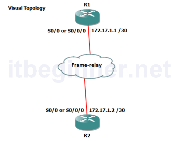
Physical Topology Diagram
- Visual Topology
- Command Line
- Task 1: Setting up a basic Frame-relay link
- Task 2: Supporting Frame-relay using sub-interfaces
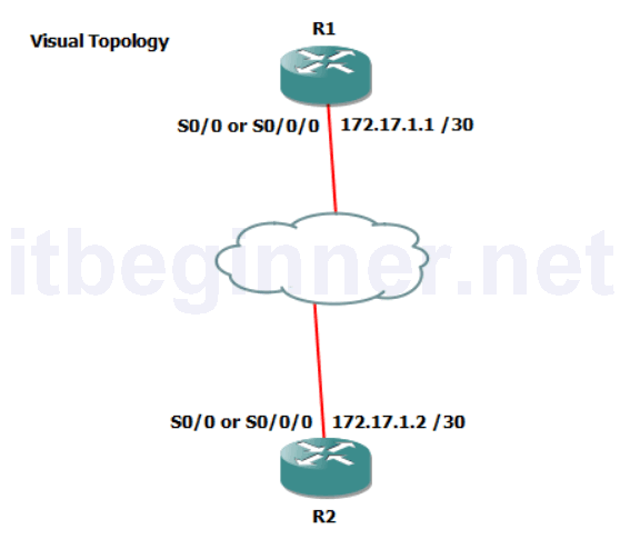
Visual Topology
Command Line
| Command | Description |
|---|---|
| encapsulation Frame-relay | Enables Frame-relay encapsulation on an interface |
| Frame-relay interface-dlci dlci | Assigns a DLCI to an interface or subinterface |
| Interface interface.subinterface point-topoint | Creates a frame-relay point-to-point subinterface |
| Show frame-relay lmi | Display LMI statistics |
| Show frame-relay pvc | Displays PVC characteristics |
| Show frame-relay map | Displays the mapping between the local DLCI and the next hop IP address. |
Task 1: Setting up a Basic Frame-relay Link.
Step 1: Access the CLI on the router.
Step 2: Disable the serial interface
Step 3: Remove the current IP address
R(config-if)#no IP address
Step 4: Change the encapsulation to Frame-relay
Task 2: Supporting Frame-relay using Subinterfaces
In this task the two routers will take on different frame-relay roles, R1 will act as the Framerelay DCE and R2 will become a Frame-relay DTE
Step 1: R1 only….
The following commands will setup Frame-relay switching, Frame-relay DCE and a framerelay point-to-point subinterface on router R1.
R1(config)#frame-relay switching
R1(config)#interface s0/0.111 point-to-point
R1(config-subif)#ip address 172.17.1.1 255.255.255.252
R1(config-subif)#frame-relay interface-dlci 111
R1(config-fr-dlci)#end
R1#conf t
R1(config)#interface s0/0
R1(config-if)#frame-relay intf-type dce
R1(config-if)#no shut
Step 1: R2 only…. Acting as a Frame-relay DTE client.
R2(config)#interface s0/0.111 point-to-point
R2(config-subif)#ip address 172.17.1.2 255.255.255.252
R2(config-subif)#frame-relay interface-dlci 111
R2(config-fr-dlci)#end
R2#conf t
R2(config)#interface s0/0
R2(config-if)#no shut
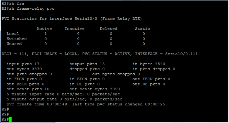
Step 2: Execute the sh frame-relay pvc command.
Below are example snapshots.
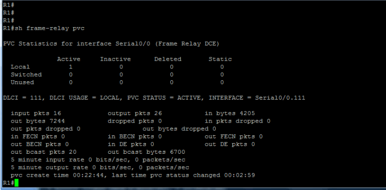
What are the 3 possible states of a PVC?
When are frame marked DE?
Step 3: Ping the IP address of the Peer device, this should be successful!
Lab Answer Keys:
[sociallocker id=”4139″]
Task 1: Setting up a Basic Frame-relay Link.
Step 2: Disable the serial interface
R(config-if)#shut
Step 3: Remove the current IP address
R(config-if)#no IP address
Step 4: Change the encapsulation to Frame-relay
R(config-if)#encap frame-relay
Task 2: Supporting Frame-relay using Subinterfaces
In this task the two routers will take on different frame-relay roles, R1 will act as the Framerelay DCE and R2 will become a Frame-relay DTE
Step 1: R1 only….
The following commands will setup Frame-relay switching, Frame-relay DCE and a framerelay point-to-point subinterface on router R1.
R1(config)#frame-relay switching
R1(config)#interface s0/0.111 point-to-point
R1(config-subif)#ip address 172.17.1.1 255.255.255.252
R1(config-subif)#frame-relay interface-dlci 111
R1(config-fr-dlci)#end
R1#conf t
R1(config)#interface s0/0
R1(config-if)#frame-relay intf-type dce
R1(config-if)#no shut
Step 1: R2 only…. Acting as a Frame-relay DTE client.
R2(config)#interface s0/0.111 point-to-point
R2(config-subif)#ip address 172.17.1.1 255.255.255.252
R2(config-subif)#frame-relay interface-dlci 111
R2(config-fr-dlci)#end
R2#conf t
R2(config)#interface s0/0
R2(config-if)#no shut
Step 2: Execute the sh frame-relay pvc command.
R#sh frame-relay pvc
Step 3: Ping the IP address of the Peer device, this should be successful!
Step 4: Once you have completed the exercise, please erase the startup-config on both the router and the switch.
R#erase startup-config
[/sociallocker]