Lab 1-2: Optimizing STP
Physical Topology Diagram
- Visual Topology
- Command List
- Task 1: Verify STP operation.
- Task 2: Manipulating Root Bridge selection.
- Task 3: Configuring Rapid Spanning-tree
- Task 4: Using STP Portfast.
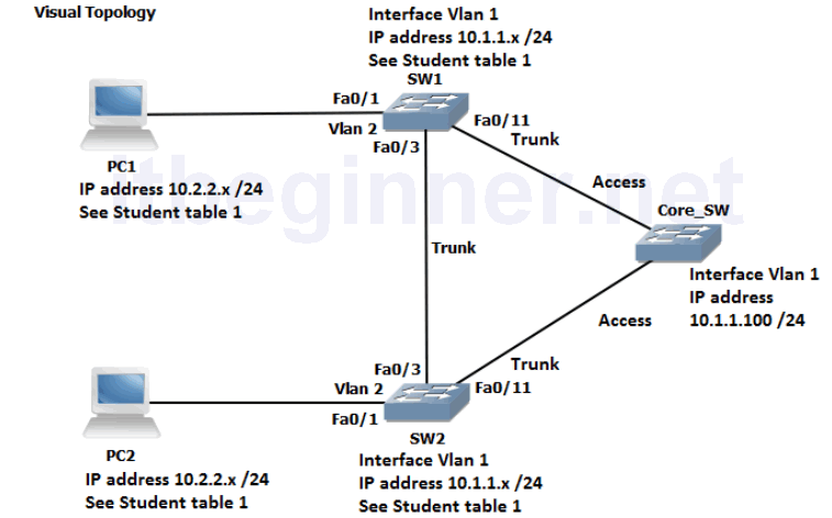
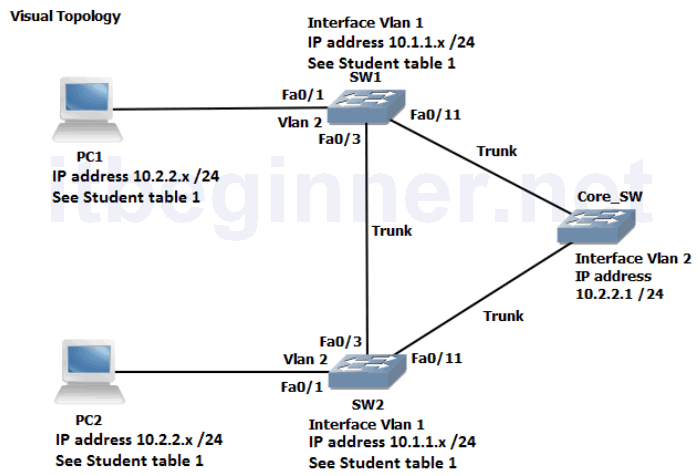
Visual Topology
Command List
| Command | Description |
|---|---|
| Configure Terminal | Enters global configuration mode. |
| Copy run start | Saves the dynamic running-config to NVRAM. |
| [no] debug spanning-tree events | |
| Interface Fastethernet 0/0 | Specifies interface fa0/0 |
| Interface Gigabitethernet 0/0 | Specifies interface gi0/0 |
| Ping ip-address or hostname | Checks IP connectivity |
| Show Interface Fastethernet 0/0 | Displays information about interface fa0/0 |
| Show Interface Gigabitethernet 0/0 | Displays information about interface gi0/0 |
| Show IP Interface Brief | Displays a brief summary of the device interfaces |
| Show spanning-tree summary | STP summary of port states and operational status |
| Show spanning-tree vlan id | Displays spanning-tree information for a specified VLAN |
| Show spanning-tree vlan id root detail | Displays detailed spanning-tree status |
| Show vlan | |
| Shutdown/ No Shutdown | Disables or enable an interface |
| [no] spanning-tree bpduguard enable | Disable or enables the BPDU guard feature on a port |
| Spanning-tree mode rapid-PVST | Enables Per-VLAN rapid spanning-tree |
| Spanning-tree portfast | Enables STP portfast feature on a port |
| Spanning-tree vlan id root primary | Forces this switch to be the root bridge for a specified VLAN |
| Spanning-tree vlan id root secondary | Sets the switch to become the new root bridge if the current root bridge fails |
| Switchport mode trunk | Statically configures the port for trunking |
| Switchport nonegotiate | Disables DTP |
| Switchport trunk allowed vlan vlan list | Filters which VLAN’s are permitted across a trunk connection. |
Student table 1
| Student ID | PC IP address & mask | Switch SVI (VLAN 1) IP address | VLAN assignments | |
|---|---|---|---|---|
| Pair 1 | Student 1 | 10.2.2.101 /24 | 10.1.1.1 /24 | 2 & 3 |
| Pair 1 | Student 2 | 10.2.2.102 /24 | 10.1.1.2 /24 | 2 & 3 |
| Pair 2 | Student 3 | 10.2.2.103 /24 | 10.1.1.3 /24 | 2, 4 & 5 |
| Pair 2 | Student 4 | 10.2.2.104 /24 | 10.1.1.4 /24 | 2, 4 & 5 |
| Pair 3 | Student 5 | 10.2.2.105 /24 | 10.1.1.5 /24 | 2, 6 & 7 |
| Pair 3 | Student 6 | 10.2.2.106 /24 | 10.1.1.6 /24 | 2, 6 & 7 |
| Pair 4 | Student 7 | 10.2.2.107 /24 | 10.1.1.7 /24 | 2, 8 & 9 |
| Pair 4 | Student 8 | 10.2.2.108 /24 | 10.1.1.8 /24 | 2, 8 & 9 |
| Pair 5 | Student 9 | 10.2.2.109 /24 | 10.1.1.9 /24 | 2, 10 & 11 |
| Pair 5 | Student 10 | 10.2.2.110 /24 | 10.1.1.10 /24 | 2, 10 & 11 |
| Pair 6 | Student 11 | 10.2.2.111 /24 | 10.1.1.11 /24 | 2, 12 & 13 |
| Pair 6 | Student 12 | 10.2.2.112 /24 | 10.1.1.12 /24 | 2, 12 & 13 |
| Pair 7 | Student 13 | 10.2.2.113 /24 | 10.1.1.13 /24 | 2, 14 & 15 |
| Pair 7 | Student 14 | 10.2.2.114 /24 | 10.1.1.14 /24 | 2, 14 & 15 |
| Pair 8 | Student 15 | 10.2.2.115 /24 | 10.1.1.15 /24 | 2, 16 & 17 |
| Pair 8 | Student 16 | 10.2.2.116 /24 | 10.1.1.16 /24 | 2, 16 & 17 |
Student table 2
| Student ID | Spanning-tree root bridge primary | Spanning-tree root bridge secondary | |
|---|---|---|---|
| Pair 1 | Student 1 | Vlan 2 | Vlan 3 |
| Pair 1 | Student 2 | Vlan 3 | Vlan 2 |
| Pair 2 | Student 3 | Vlan 4 | Vlan 5 |
| Pair 2 | Student 4 | Vlan 5 | Vlan 4 |
| Pair 3 | Student 5 | Vlan 6 | Vlan 7 |
| Pair 3 | Student 6 | Vlan 7 | Vlan 6 |
| Pair 4 | Student 7 | Vlan 8 | Vlan 9 |
| Pair 4 | Student 8 | Vlan 9 | Vlan 8 |
| Pair 5 | Student 9 | Vlan 10 | Vlan 11 |
| Pair 5 | Student 10 | Vlan 11 | Vlan 10 |
| Pair 6 | Student 11 | Vlan 12 | Vlan 13 |
| Pair 6 | Student 12 | Vlan 13 | Vlan 12 |
| Pair 7 | Student 13 | Vlan 14 | Vlan 15 |
| Pair 7 | Student 14 | Vlan 15 | Vlan 14 |
| Pair 8 | Student 15 | Vlan 16 | Vlan 17 |
| Pair 8 | Student 16 | Vlan 17 | Vlan 16 |
Before starting the Lab, confirm with the Instructor that the Core Switch has been configured with all of its ports in trunk mode (see visual diagram) and a SVI (vlan2) has been set-up and enabled with the IP address 10.2.2.1 /24.
To prevent the unwanted propagation of the vlan database from the Core_SW ask the instructor to place the Core_SW into VTP transparent mode.
To aid with your understanding of the Lab exercise and how the Core switch is configured the running-config has been provided for you.
Core_SW#sh run
!
hostname Core_SW
!
vtp mode transparent
!
spanning-tree mode pvst
!
vlan 2
name Pair1
!
vlan 3
!
vlan 4
name Pair2
!
vlan 5
!
vlan 6
name Pair3
!
vlan 7
!
vlan 8
name Pair4
!
vlan 9
!
vlan 10
name Pair5
!
vlan 11
!
vlan 12
name Pair6
!
vlan 13
!
vlan 14
name Pair7
!
vlan 15
!
vlan 16
name Pair8
!
vlan 17
!
interface FastEthernet0/1
description Link to Student 1 Switch
switchport trunk allowed vlan 1-3
switchport mode trunk
switchport nonegotiate
!
interface FastEthernet0/2
description Link to Student 2 Switch
switchport trunk allowed vlan 1-3
switchport mode trunk
switchport nonegotiate
!
interface FastEthernet0/3
description Link to Student 3 Switch
switchport trunk allowed vlan 1-2,4-5
switchport mode trunk
switchport nonegotiate
!
interface FastEthernet0/4
description Link to Student 4 Switch
switchport trunk allowed vlan 1-2,4-5
switchport mode trunk
switchport nonegotiate
!
interface FastEthernet0/5
description Link to Student 5 Switch
switchport trunk allowed vlan 1-2,6-7
switchport mode trunk
switchport nonegotiate
!
interface FastEthernet0/6
description Link to Student 6 Switch
switchport trunk allowed vlan 1-2,6-7
switchport mode trunk
switchport nonegotiate
!
interface FastEthernet0/7
description Link to Student 7 Switch
switchport trunk allowed vlan 1-2,8-9
switchport mode trunk
switchport nonegotiate
!
interface FastEthernet0/8
description Link to Student 8 Switch
switchport trunk allowed vlan 1-2,8-9
switchport mode trunk
switchport nonegotiate
!
interface FastEthernet0/9
description Link to Student 9 Switch
switchport trunk allowed vlan 1-2,10-11
switchport mode trunk
switchport nonegotiate
!
interface FastEthernet0/10
description Link to Student 10 Switch
switchport trunk allowed vlan 1-2,10-11
switchport mode trunk
switchport nonegotiate
!
interface FastEthernet0/11
description Link to Student 11 Switch
switchport trunk allowed vlan 1-2,12-13
switchport mode trunk
switchport nonegotiate
!
interface FastEthernet0/12
description Link to Student 12 Switch
switchport trunk allowed vlan 1-2,12-13
switchport mode trunk
switchport nonegotiate
!
interface FastEthernet0/13
description Link to Student 13 Switch
switchport trunk allowed vlan 1-2,14-15
switchport mode trunk
switchport nonegotiate
!
interface FastEthernet0/14
description Link to Student 14 Switch
switchport trunk allowed vlan 1-2,14-15
switchport mode trunk
switchport nonegotiate
!
interface FastEthernet0/15
description Link to Student 15 Switch
switchport trunk allowed vlan 1-2,16-17
switchport mode trunk
switchport nonegotiate
!
interface FastEthernet0/16
description Link to Student 16 Switch
switchport trunk allowed vlan 1-2,16-17
switchport mode trunk
switchport nonegotiate
!
interface Vlan1
no ip address
shutdown
!
interface Vlan2
ip address 10.2.2.1 255.255.255.0
!
end
-----Some output omitted-----
Task 1: Verify STP Operation.
Step 1: Confirm that you have interfaces fa0/1, fa0/3 and fa0/11 enabled.
Step 2: From your PC ping 10.2.2.1. This should be successful
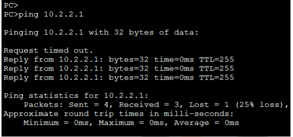
If the ping fails, check you have the correct IP address on your PC, fa0/1 is statically assigned to VLAN 2, the Trunk connection between your switch and the Core switch is operational.
Step 3: View the visual topology diagram and you will notice that a bridging loop exists between your switch, the Core switch and the switch which is being managed by the other student. Spanning-tree (STP) is enabled by default and will detect the presence of a loop and take the necessary steps to prevent the loop by blocking one of the ports.
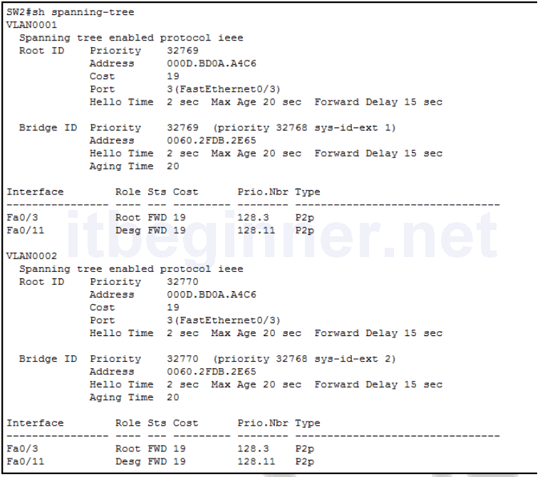
Use the show spanning-tree vlan id to determine which switch is the current Root Bridge for VLAN 1, VLAN 2 and your unique student pair VLANs.
| Student ID | Student Pair | Unique VLANs |
| Students 1 & 2 | Pair 1 | 2 & 3 |
| Students 3 & 4 | Pair 2 | 4 & 5 |
| Students 5 & 6 | Pair 3 | 6 & 7 |
| Students 7 & 8 | Pair 4 | 8 & 9 |
| Students 9 & 10 | Pair 5 | 10 & 11 |
| Students 11 & 12 | Pair 6 | 12 & 13 |
| Students 13 & 14 | Pair 7 | 14 & 15 |
| Students 15 & 16 | Pair 8 | 16 & 17 |
Would you expect to see the same Root Bridge for all VLANs?
How is the Root Bridge elected?
The following outputs are for reference only, outputs will vary.
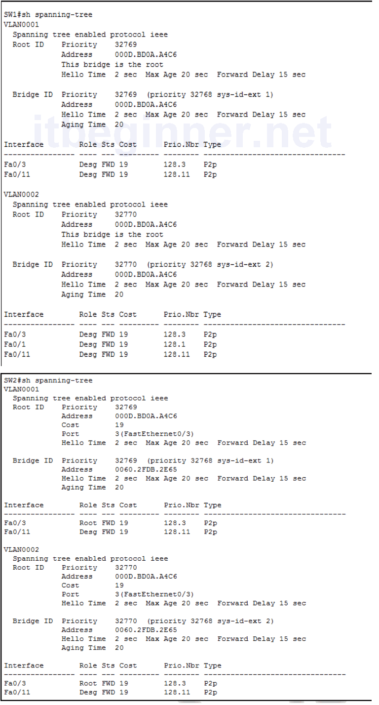
Using the information obtained from your switch complete the table below.
| Root Bridge ID for VLAN 1 | |
| Root Bridge ID for VLAN 2 | |
| Root Bridge ID for VLAN x (unique vlan in your student pair) |
|
| Root Bridge ID for VLAN x (unique vlan in your student pair) |
|
| Type of spanning-tree protocol | |
| Fa0/3 port role | |
| Fa0/3 port state | |
| Fa0/11 port role | |
| Fa0/11 port state | |
| Cost back to the Root Bridge |
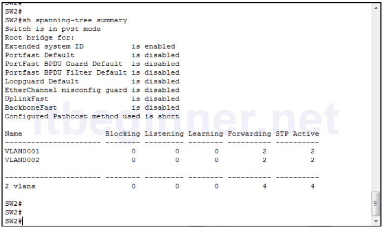
Other show commands can be used to display information about Spanning-tree
Show spanning-tree summary (output for reference only)
Show spanning-tree vlan 1 root detail
SW1#sh spanning-tree vlan 1 root detail
VLAN0001
  Root ID       Priority     32769
                Address      000D.BD0A.A4C6
                This bridge is the root
                Hello Time   2 sec Max Age 20 sec Forward Delay 15 sec

SW2#sh spanning-tree vlan 1 root detail
VLAN0001
  Root ID       Priority     32769
                Address      000D.BD0A.A4C6
                Cost         19 (FastEthernet 0/3)
                Hello Time   2 sec Max Age 20 sec Forward Delay 15 sec
We can ascertain from the output of the previous commands that in this scenario SW1 is clearly the Root Bridge and the best path to the Root Bridge for SW2 is via fa0/3 (root port).
Based on your results how did the switches decide which one of them should become the Root?
Task 2: Manipulating Root Bridge Selection.
In the previous task we used default settings, so the Root Bridge was elected based on the lowest MAC address.
Root bridge elections are pre-emptive and if a new switch is added to the network it can take over the role of the Root Bridge and influence the path decisions made by a switch when forwarding traffic. System administrators have the ability to manipulate the Root Bridge election and therefore create a more predicable switching environment.
Step 1: Using the relevant commands force your switch to become the Root bridge and a backup Root Bridge for the VLANs indicated in the table below.
| Student ID | Spanning-tree root bridge primary | Spanning-tree root bridge secondary | |
|---|---|---|---|
| Pair 1 | Student 1 | Vlan 2 | Vlan 3 |
| Pair 1 | Student 2 | Vlan 3 | Vlan 2 |
| Pair 2 | Student 3 | Vlan 4 | Vlan 5 |
| Pair 2 | Student 4 | Vlan 5 | Vlan 4 |
| Pair 3 | Student 5 | Vlan 6 | Vlan 7 |
| Pair 3 | Student 6 | Vlan 7 | Vlan 6 |
| Pair 4 | Student 7 | Vlan 8 | Vlan 9 |
| Pair 4 | Student 8 | Vlan 9 | Vlan 8 |
| Pair 5 | Student 9 | Vlan 10 | Vlan 11 |
| Pair 5 | Student 10 | Vlan 11 | Vlan 10 |
| Pair 6 | Student 11 | Vlan 12 | Vlan 13 |
| Pair 6 | Student 12 | Vlan 13 | Vlan 12 |
| Pair 7 | Student 13 | Vlan 14 | Vlan 15 |
| Pair 7 | Student 14 | Vlan 15 | Vlan 14 |
| Pair 8 | Student 15 | Vlan 16 | Vlan 17 |
| Pair 8 | Student 16 | Vlan 17 | Vlan 16 |
Step 2: Verify step 1 using show commands.
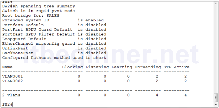
Task 3: Configuring Rapid Spanning-tree
The default spanning-tree protocol on Cisco device is PVST+ (802.1D + 802.1Q) Ask the Instructor to change the Core Switch.
NB. You may need to wait for other students to catch up.
Step 1: Configure PVRST+
Step 2: Use an appropriate command to verify the change.
Step 3: Disable interface fa0/3
Step 4: Save your running-config
Task 4: Using STP Portfast
Spanning-tree portfast is used to transition a port straight from the spanning-tree blocking state to the spanning-tree forward state, it usually take less than 1 second for the port to become operational.
Step 1: Disable fa0/1 and configure it to use spanning-tree portfast.
Step 2: Run the following debug command.
Sw#debug spanning-tree events
Step 3: Enable fa0/1 and monitor the output of the debug command.
Look for a line similar to this, it should appear very soon after you enable the port.
Aug 15 17:10:45.529: STP: VLAN0002 Fa0/1 ->jump to forwarding from blocking
Step 4: Save your running-config
Lab Answer Keys:
[sociallocker id=”4139″]
Task 1: Verify STP Operation.
Confirm with the Instructor that the Core Switch has been configured with all of its ports in trunk mode (see visual diagram) and a SVI (vlan2) has been set -up and enabled with the IP address 10.2.2.1 /24
Step 1: Confirm that you have interfaces fa0/1, fa0/3 and fa0/11 enabled.
SW#sh ip int brief
Step 3: Would you expect to see the same Root Bridge for both VLANs?
Yes.
All switches are using defaults bridge priorities for all vlans.
How is the Root Bridge elected?
Lowest BID
The BID is a combination of a 16 bit bridge priority and a 48 bit base mac address. The bridge priority is the primary selection criteria and is set to 32768 by default, the mac address will only be used to determine the Root Bridge if the priorities are equal on all switches involved in the spanning-tree instance.
Using the information obtained from your switch complete the table below.
Table values are based on the output above and should be used for reference only.
| Root Bridge ID for VLAN 1 | 32769.000D.BD0A.A4C6 |
| Root Bridge ID for VLAN 2 | 32770.000D.BD0A.A4C6 |
| Type of spanning-tree protocol | IEEE (default Cisco PVST+) |
| Fa0/3 port role | Root |
| Fa0/3 port state | Forwarding |
| Fa0/11 port role | Designated |
| Fa0/11 port state | Forwarding |
| Cost back to the Root Bridge | 19 |
Based on your results how did the switches decide which one of them should become the Root?
Best (lowest values) BID
Task 2: Manipulating Root Bridge Selection.
In the previous task we used default settings, so the Root Bridge was elected based on the lowest MAC address.
Root bridge elections are pre-emptive and if a new switch is added to the network it can take over the role of the Root Bridge and influence the path decisions made by a switch when forwarding traffic. System administrators have the ability to manipulate the Root Bridge election and therefore create a more predicable switching environment.
Step 1:
SW1 only.....
**IMPORTANT, the following commands illustrate the use of the command structure**
Using the relevant commands, force the switch to become the Root bridge for VLAN 1 and a backup Root Bridge for VLAN 2 if SW2 fails.
SW1(config)#spanning-tree vlan 1 root primary (use the vlan identify in the table)
SW1(config)#spanning-tree vlan 2 root secondary (use the vlan identify in the table)
SW2 only.....
Using the relevant commands, force the switch to become the Root bridge for VLAN 2 and a backup Root Bridge for VLAN 1 if SW1 fails.
SW2(config)#spanning-tree vlan 1 root secondary (use the vlan identify in the table)
SW2(config)#spanning-tree vlan 2 root primary (use the vlan identify in the table)
Task 3: Configuring Rapid Spanning-tree
Step 1: Configure PVRST+
SW(config)#spanning-tree mode rapid-pvst
Step 3: Disable interface fa0/3
SW(config)#int fa0/3
SW(config-if)#shut
Step 4: Save your running-config
SW#copy run start
Task 4: Using STP Portfast
Spanning-tree portfast is used to transition a port straight from the spanning-tree blocking state to the spanning-tree forward state, it usually take less than 1 second for the port to become operational.
Step 1: Disable fa0/1 and configure it to use spanning-tree portfast.
SW(config)#int fa0/1
SW(config-if)#shut
SW(config-if)spanning-tree portfast
Step 3: Enable fa0/1 and monitor the output of the debug command.
SW(config-if)#no shut
Look for a line similar to this, it should appear very soon after you enable the port.
Aug 15 17:10:45.529: STP: VLAN0002 Fa0/1 ->jump to forwarding from blocking
Step 4: Save your running-config
SW#copy run start
[/sociallocker]